Aeroelastic Responses for Wind Turbine Blade Considering Bend-Twist Coupled Effect
2016-05-12LiYijinWangTongguang
Li Yijin,Wang Tongguang
Jiangsu Key Laboratory of Hi-Tech Research for Wind Turbine Design,Nanjing University of Aeronautics and
Astronautics,Nanjing 210016,P.R.China
(Received 4 August 2015; revised 13 November 2015; accepted 5 January 2016)
Aeroelastic Responses for Wind Turbine Blade Considering Bend-Twist Coupled Effect
Li Yijin,Wang Tongguang*
Jiangsu Key Laboratory of Hi-Tech Research for Wind Turbine Design,Nanjing University of Aeronautics and
Astronautics,Nanjing 210016,P.R.China
(Received 4 August 2015; revised 13 November 2015; accepted 5 January 2016)
Abstract:The Euler-Bernoulli beam model coupled with the sectional properties obtained by the variational asymptotic beam sectional analysis (VABS) method is used to construct the blade structure model.Combined the aerodynamic loads calculated by unsteady blade element momentum model with a dynamic inflow and the dynamic stall correction,the dynamics equations of blade are built.The Newmark implicit algorithm is used to solve the dynamics equations.Results of the sectional properties and blade structure model are compared with the multi-cell beam method and the ANSYS using shell elements.It is proved that the method is effective with high precision.Moreover,the effects on the aeroelastic response caused by bend-twist coupling are analyzed.Torsional direction is deflected toward the upwind direction as a result of coupling effects.The aerodynamic loads and the displacement are reduced.
Key words:variational asymptotic beam sectional analysis (VABS) ; wind turbine; unsteady blade element momentum theory; dynamic stall; aeroelastic responses
CLC number: TK83Document code: AArticle ID: 1005-1120(2016)01-0016-10
* Corresponding author,E-mail address: tgwang@ nuaa.edu.cn.
How to cite this article: Li Yijin,Wang Tongguang.Aeroelastic responses for wind turbine blade considering bend-twist coupled
effect[J].Trans.Nanjing Univ.Aero.Astro.,2016,33(1) : 16-25.
http: / /dx.doi.org/10.16356/j.1005-1120.2016.01.016
0 Introduction
The global cumulative installed wind capacity has been increased very fast during the past decades,in nearly exponential growth according to the reports by the Global Wind Energy Council[1].The fast growth was supported not only by a large number of new installed farms,but especially by the increased power output of single wind turbine.Nowadays for the offshore wind farms,the power with 6—8 MW is available on the market,and the length of blades reaches 80 m.Future wind turbine will have even larger scale and it is expected to reach 20 MW with the length of blades up to 150 m by 2020.To reduce the weight and increase the fatigue life of the system,composite materials such as glass fiber or carbon fiber reinforced plastics have been used because of their high strength-to-weight-ratios along with superb fatigue properties.With increasing size and the using of anisotropic materials,bending and torsional natural frequencies of the blades were closer to each other.The reliable prediction of the aeroelastic response caused by the bend-twist coupling effects became very important for the multi-mega watt (multi-MW ) wind turbines.And also the passive control using the blade own structure is an effective method to decrease the sharply increased loads of future wind turbines.
Some studies have been carried out on the effects of bend-twist coupling recently.Lobitz[2-4]used the classical flutter theory which considered the flap-twist coupling to calculate the dynamic response of HAWT blades.The load characteristics and the performance caused by coupling effects were analyzed.Nicholls-Lee[5]compared the results between the non-coupled and coupled of theblades.And it showed that a decrease of up to 12% in thrust and an increase of up to 5%in power capture could be achieved by the use of properly designed,bend-twist coupled blades.A novel differential stiffness bend-twist (DSBT ) coupling concept is proposed by Herath[6]to control the deformation behavior of the blades.The DSBT method achieved bend-twist coupling in the global structure while allowing the main deformation of the structural sub-components to remain in pure bending.Goeij[7]modelled a complete blade with spar webs by using the FEM program to investigate the performance of bending-torsion coupling composite wind turbine rotor blade.Suitable torsional vibration caused by the aeroelastic effects could create better power production and reduce the vibration.Otherwise,it is found that this could suffer from flutter,substantial fatigue damage reductions[8-9].Ashwill[10]reported the fatigue load examination on the bend-twist blades.The bend-twist coupled blade failed at over 4 million cycles,which was around twice the designed service life of 2 million cycles.Also,some experiments have been conducted to study the mechanism of bend-twist coupling.A number of improved full-scale tests were performed on a wind turbine blade section provided by Vestas,and different FEM approaches for predicting the torsional response of the bend-twist coupling were examined in Technical University of Denmark[11-12].The results showed that shell models performed well for flap-wise bending,but performed poorly in torsion with deviations in the range of 15%—35%.Also in the past several years,two prototype blades,the 9 m TX-100 blade and the 27 m STAR blade that all induced bend-twist coupling,have been tested to investigate the load reduction with passive control in Sandia National Laboratories[13].
The main objective of the present study is to investigate the aeroelastic response caused by the bend-twist coupling effects in composite wind turbine blades.An effective method with high precision is proposed to model the blade structure by combining the properties of two-dimensional (2-D) section calculated by the variational asymptotic beam sectional analysis (VABS)[14]method and the 1-D Euler-Bernoulli beam model.Results are compared with the multi-cell beam method and the ANSYS using shell elements.The blade element momentum (BEM ) method considering the dynamic inflow[15]and the dynamic stall model[16]is used to calculate the unsteady aerodynamic[17].Fully coupling of the structure model and the aerodynamic model is achieved in program to calculate the aeroelastic response of the wind turbine blade in wind with the shear effect.The influence on the vibration displacement and unsteady loads caused by the bend-twist coupling effects are analyzed.
1 Structural Model of Wind Turbine Blades
The wind turbine blades are slender structures with one dimension much larger than the other two.And the first several elastic modals demonstrate the beam behavior.For this reason,the FEM models based on the brick or shell elements are believed to be overcorrected for aeroelastic analysis especially in the multi-body dynamics calculation of the whole wind turbine system[18].It is also proved that if the beam models of composite blades are appropriately constructed,it can obtain almost the same accuracy as the three-dimen-sional (3-D) FEM method[19].But the cost of beam models is two to three orders of magnitude less.
To evaluate the sectional properties both structurally and inertially for composite beams has also been an active research field in recent years.Particularly for the wind turbine blades,several tools are commonly used,including PreComp[20],VABS,FAROB[21],CROSTAB[22]and BPE[23].Chen[24]briefly summarized the theoretical foundation of each approach and pointed out the advantages and disadvantages of each approach.Compared the results of different tools,it showed that both mass and stiffness coefficients obtained by VABS are almost exactly the same as those calculated by the elasticity theory.The maximum error was less than 0.19%.The observation also con-firmed the proof in Yu and Hodges' study[25]that VABS could reproduce the elasticity theory results for isotropic prismatic beams.
To analyze a beam,an arbitrary reference line r should be specified,as shown in Fig.1.Any material point of the beam in 3-D space can be located by a position vector r.It is specified by the beam axial coordinate system,where x1is along r and the cross-sectional Cartesian coordinates (x2,x3) are embedded in a chosen reference cross-section.At each point along r,an orthogonal reference triad biis introduced such that bαis tangent to xα.Hence the spatial position vector^r of any point in the cross-section can be written as

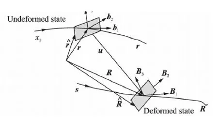
Fig.1 Schematic of beam deformation
When the beam deforms,the triad birotates to the new triad Bi.Here B1is not along r if shear deformation is considered.For convenience,another triad Tiassociated with the deformed beam is introduced where T1is tangent to the deformed beam reference line.The position vector of any particle in the deformed beam which had position^r in the undeformed beam can be represented as

where R is the position vector to a point on the reference line of the deformed beam,and withe components of warping.
Consistent with the geometrically exact framework of Hodges,the moment-strain measures κiare defined based on the changes along x1of the triad Ti.

where k1is the initial twist and k2,k3,k4are the initial curvatures.
It should be noted that Eq.(2) is four times redundant because of the way in which warping is introduced.Four appropriate constraints on the displacement field should be imposed to remove the redundancy.The four constraints applied are

where the notation《·》= 0 means integration over the reference cross section.
Based on the concept of the rotation tensor decomposition,the Jauman-Biot-Cauchy strain components for small local rotation are given by

Discarding the product of the warping and 1-D generalized strains,the 3-D strain field can be expressed as

The strain energy of the cross section or the strain energy density of the beam can be written as

where the notation〈·〉=∫sx2dx3.ζ is 6×6 symmetric material matrix in the bibasis.
In order to deal with arbitrary cross-sectional geometry and anisotropic materials,a numerical approach is adopted to find the stationary value of the function.The warping field can be discretized as

where S(x2,x3) represens the element shape function and V a column matrix of the nodal values of the warping displacement over the cross-section.Substituting Eq.(9) back into Eq.(8),one obtains strain energy.The detailed expressions could be found in Ref.[25].
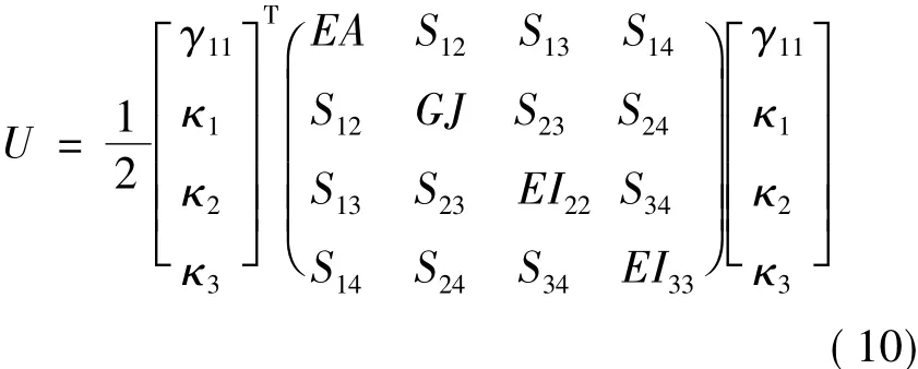
For the Euler-Bernoulli beam model which is capable of dealing with extension,torsion and bending in two directions,the strain energy can be written as
where γ11,κ1,κ2,κ3are the extensional strain,twist,bending curvatures about x2and x3,respectively.The diagonal terms EA,GJ,EI22,EI33are the extensional stiffness,the torsional stiffness and the bending stiffness about x2and x3.The off diagonal terms represent the elastic couplings between different deformation modes.
2 Aerodynamic Loads
The BEM method is the most commonly used one for calculating the aerodynamic loads on wind turbine rotors.Compared with the vortex wake model[26]or the Navier-Stokes solvers[27],BEM method is computationally cheap and very fast.And based on the accurate airfoil data and some necessary corrections,the results are with good accuracy.The unsteady BEM method is used in the paper.Also the Prandtl's tip loss correction[28],yaw correction,dynamic inflow model and the dynamic stall model are all considered to improve the precision of aerodynamic calculation.The relative velocity to the blade is added,as shown in Fig.2.

where V0is the undisturbed wind velocity,Vrotthe rotational velocity,W the induced velocity,and Vbthe vibrational velocity of blade.
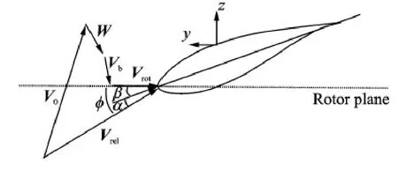
Fig.2 Velocity triangle seen locally on a blade
From a global consideration the rotor acts as a disc with a discontinuous pressure drop across it.The thrust generated by this pressure drop induces a velocity as

where B is the number of blades,L the lift computed from the lift coefficient, the flow angle,ρ the density of air,r the radial position considered,V0the wind velocity,W the induced velocity,fgthe Glauert correction,and n the normal vector to the rotor plane.F is the Prandtl's tip loss correction that corrects the equations to be valid for a finite number of blades.
The induced velocities calculated using Eqs.(12),(13 ) are quasi-steady.If the loads are changed in time,there is a time delay before a new equilibrium achieved.A dynamic inflow model proposed by Ref.[16]was applied.It is described up by two first-order differential equations.

where Wqsis the quasi-static value,Wintan intermediate value and W the final filtered value to be used as the induced velocity.τ1and τ2are the two time constants.
The effect of the blades attack angle changing does not appear instantaneously.There is also a time delay proportional to the chord divided with the relative velocity.The response of the aerodynamic load depends on whether the boundary layer is attached or partly separated.For the attached flow,the time delay can be estimated using the Theodorsen theory for unsteady lift and aerodynamic moment.Trailing edge stall,also called the dynamic stall,can be modelled by a separation function fs,i.e.

where Cl,invdenotes the lift coefficient for an inviscid flow without any separation,fsthe degree of trailing edge stall,and Cl,fsthe lift coefficient for a fully separated flow.
3 Method for Aeroelastic Response Analysis
The Euler-Bernoulli beam method is used to set up the mass matrix M,stiffness matrix K,and damping matrix C,for a discretized mechanical system as

where F denotes the generalized force vector composed of the aerodynamic loads,gravity and centrifugal loads.
In order to obtain the higher order terms and improve the convergence effect,the Newmark implicit algorithm is used to solve Eq.(17).From time t to t + dt,the following assumptions are maken in the Newmark integral method.


where α and δ are the parameters with regard to the demand of accuracy and stability.
And from Eqs.(18),(19),the acceleration at time t + dt can be solved as

The whole progress to calculate the aeroelastic response of the wind turbine blades is shown in Fig.3.

Fig.3 Flowchart of the aeroelastic model
4 Results
The blade NH1500 is selected for the aeroelastic calculation.The rated power is 1.5 MW at a rotation speed of 17.2 r/min-1.The blade length is 41 m,and the rate velocity 10 m /s.Based on this model,structural and inertial properties of the blade section are calculated.Combined with the Euler-Bernoulli beam model,the modals of the blade are achieved and results are compared with ANSYS using the shell elements.Coupled with the unsteady aerodynamic load,the aeroelastic response of blade working in shear wind is calculated.
4.1Section properties and blade modal
The multi-cell beam model as an engineering approach is usually used for the calculation of normal stress and shear stress on the aircraft.Very few computational resources are needed and the results exhibit enough accuracy for the isotropic materials.It is also used for the calculation of wind turbine blades to get the structural and initial properties of the blade sections.Fig.4 shows the mass density and inertia in three different directions calculated by the VABS method and the multi-cell method.Although the blades are made of composite materials,the density as scalar does not have directions.The two methods almost have the same results.The difference between edgewise inertia and torsional inertia is mainly attributed to the different treatment of the beam at trailing edge.
The extensional stiffness,bending stiffness intwo directions are shown in Fig.5,as well as torsional stiffness,bending center in the edgewise direction,and the principal inertial axes rotated from the sectional coordinate system.The VABS method and multi-cell method are in good agreement with each other in terms of most properties.The influence caused by the anisotropic materials does not show much difference in the extensional and bending stiffness.But for the torsional stiffness,results calculated by the VABS method considering the nonhomogeneous,initially curved and anisotropic beam display much difference.Also,the elastic coupling terms in Eq.(10) could be achieved by the VABS method as Fig.6.

Fig.4 Mass density and inertia in different directions
The properties in Figs.4—6 are described by the sectional coordinate system.And to model the blade with a Euler-Bernoulli beam,these parameters are modified to the location of the bending center.Table 1 lists the first five-order modal calculated by the beam model with properties achieved by the multi-cell method and VABS method,and the ANSYS using the shell elements.Being relative to the results of multi-cell method,the natural frequency using the VABS method is more close to the results of ANSYS because of the more accurate cross sectional properties.And the relative errors of the first five-order modal using the VABS method are all under 5%.Figs.7,8 show the vibration component in different directions of the first two-order vibration modal.To demonstrate them clearly,the unit of torsion is chosen as degree.There is little difference among the three methods in terms of the main vibration direction,the flapwise of the first-order modal,and the edgewise of the second-order modal.So the results using the multi-cell method are with good accuracy for the aeroelastic calculation if the flapwise vibration and edgewise vibration are considered independently.But with the increasing size,the using of anisotropic materials,the initially curved and twisted of wind turbine blades,the flap-edge coupling and bend-twist coupling effects will be more significant.The flap-edge coupling can be simulated using the beam model with the multi-cell method.But results in another bending direction are with a poor accuracy,as shown in Figs.7,8.Using the VABS method,each coupling terms can be obtained.Results achieved by combining the beam model and the sectional properties obtained by the VABS method agree well with the results using shell elements.Both in the main vibration direction and in the other bending and torsional directions the results are with good accuracy.And the cost of beam models with the VABS method isthree orders of magnitude less.The method can effectively and precisely model the blade structure.
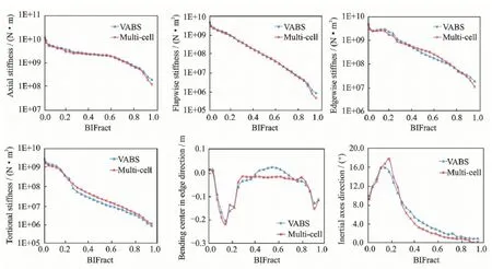
Fig.5 Properties distributions
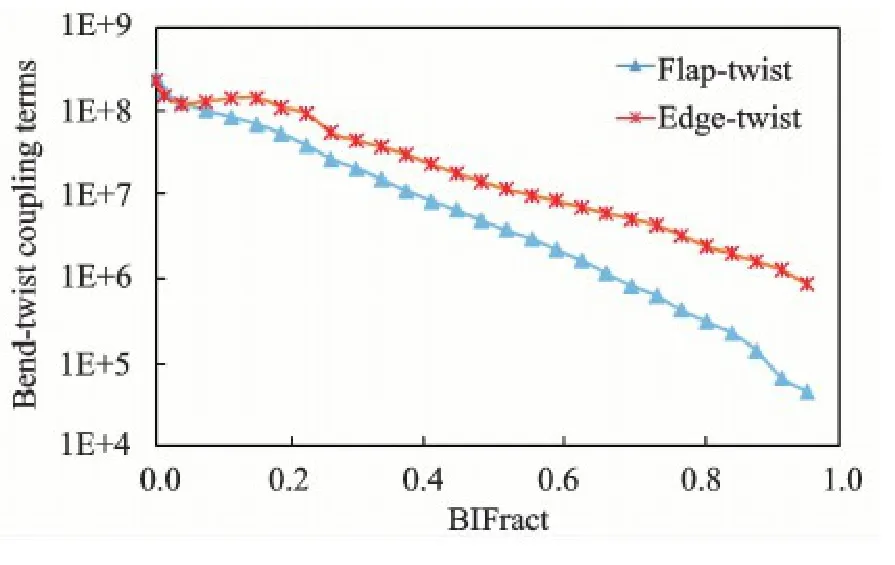
Fig.6 Bend-twist coupling properties distribution

Table 1 Comparison of natural frequency
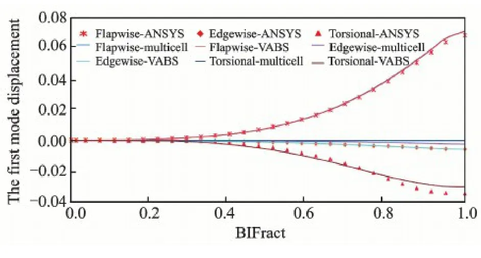
Fig.7 The first-order natural vibration model of blade
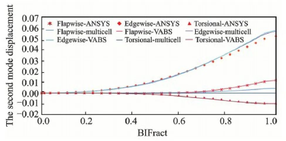
Fig.8 The second-order natural vibration model of blade
4.2Aeroelastic response of blade
The operating condition with wind speed of 10 m /s and rotational speed of 17.2 r/min is selected for the aeroelastic response simulation.The pitch angle of the blade is 0°.And the exponential model is used to simulate the wind shear effect caused by the atmospheric layer and the shear coefficient is 0.17.Two models with the consideration of the bend-twist coupling effects and without consideration of the coupling effects,are calculated.The results are compared with the GH Bladed ones.
The attack angle and the aerodynamic load out ofthe rotational plane at r =31.5 m span are shown in Figs.9,10.Due to gravity and wind shear effect,the angle and load are changed periodically.Results with considering non-coupling effect agree well with the GH Bladed results.Only the amplitude is slightly smaller,mainly because of the different treatment of the structure damping.And the vibrational period and the phase are consistent with the aerodynamic load as shown in Figs.9,10.It is proved that the aerodynamic model,the structure model and the direct integration method are constructed correctly.The bendtwist coupling effects increase the torsional deformation due to the flapwise and edgewise deformation.This leads to the decrease in angle of attack.Thus the aerodynamic load out of plane aerodynamic decreases.
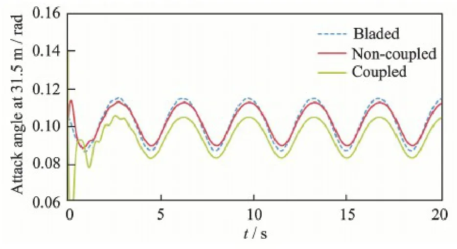
Fig.9 Attack angle at r =31.5 m span
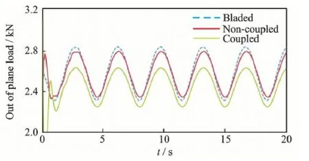
Fig.10 Out of plane aerodynamic loading for blade at r =31.5 m span
The displacement responses at the blade tip in flapwise and edgewise directions are shown in Figs.11,12.Results with non-coupling effects are also in consistent with the GH Bladed results.And since the vibration in the flapwise direction is mainly excited by the periodic aerodynamic loads,the average displacement with the coupling effects is reduced as shown in Fig.11.The average displacement decreases from 2.52 m to 2.35 m with a decline of 6.95%.The displacement response in the edgewise direction is mainly excited by the gravity.With the rotation of the wind rotor,the gravity load changes periodically in the edgewise direction.The average displacement and amplitude calculated by considering the coupling effects are almost the same as those of the GH Bladed.The small difference is caused by the aerodynamic loads at the rotational plane.
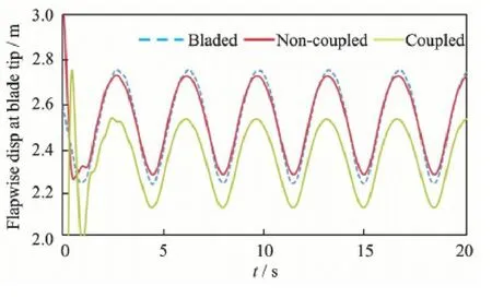
Fig.11 Flapwise displacement response at blade tip
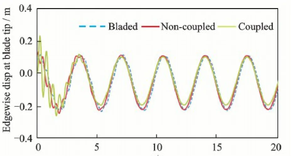
Fig.12 Edgewise displacement response at blade tip
5 Conclusions
The VABS method is used to calculate the inertial and structural properties for the sections of the wind turbine blades in the present study.The extensile,bending and torsional stiffness are obtained with good accuracy.Also the coupling effects for the composite,initially curved and twisted blades are obtained.The results by the Euler-Bernoulli beam model combining the properties achieved by the VABS method agree well with the results using the shell elements.And the beam model is with better calculation efficiency.Based on the beam model,the effects on the aeroelastic response caused by the bend-twist coupling are analyzed.The coupling effects make the torsional direction deform toward the upwind direction.Due to these facts,the aerodynamic loads and dis-placement are reduced.
Acknowledgements
This work was supported jointly by the National Basic ResearchProgramof China(″973″Program )(No.2014CB046200),the Natural Science Foundation of Jiangsu Province (No.BK2014059),the Priority Academic Program Development of Jiangsu Higher Education Institutions,and the National Natural Science Foundation of China (No.11172135).
References:
[1]WISER R,BOLINGER M,BARBOSE G,et al.2012 Wind Technologies Market Report[R].Capacity,2013.
[2]LOBITZ D W,VEERS P S.Aeroelastic behavior of twist-coupled HAWT blades[J].Wind Energy,1998,1(S1) : 46-69.
[3]LOBITZ D W,LAINO D J.Load mitigation with twistcoupled HAWT blades[C]∥ASME/AIAA Wind Energy Symposium.Reno,NV:[s.n.],1999: 124-134.
[4]LOBITZ D,VEERS P,LAINO D.Performance of twistcoupled blades on variable speed rotors[C]∥2000 ASME Wind Energy Symposium.Reno,NV,USA: AIAA,2000.
[5]NICHOLLS-LEE R F,TURNOCK S R,BOYD S W.Application of bend-twist coupled blades for horizontal axis tidal turbines[J].Renewable Energy,2013,50 (3) : 541-550.
[6]HERATH M T,LEE A K L,PRUSTY B G.Design of shape-adaptive wind turbine blades using differential stiffness bend-twist coupling[J].Ocean Engineering,2015,95(1) : 157-165.
[7]GOEIJ W C D,TOOREN M J L V,BEUKERS A.Implementation of bending-torsion coupling in the design of a wind-turbine rotor-blade[J].Applied Energy,1999,63(3) : 191-207.
[8]LOBITZ D W,VEERS P S.Load mitigation with bending/twist-coupled blades on rotors using modern control strategies[J].Wind Energy,2003,6(2) : 105-117.
[9]LOBITZ D W.Aeroelastic stability predictions for a MW-sized blade[J].Wind Energy,2004,7(3) : 211-224.
[10]ASHWILL T D.Materials and innovations for large blade structures: Research opportunities in wind energy technology[J].14 Solar Energy; 17 Wind Energy; Carbon Dioxide; Electricity; ManufactUrers; National Renewable Energy Laboratory; Rotors; Sandia National Laboratories; Wind Turbines,2009.
[11]BRANNER K,BERRING P,BERGGREEN C,et al. Torsional performance of wind turbine blades part II: Numerical validation[C]∥16th International Conference on Composite Materials.Salzburg: Elsevier,2007.
[12]FEDOROV V,DIMITROV N K,BERGGREEN C.Investigation of structural behaviour due to bend-twist couplings in wind turbine blades[C].ICCM International Conferences on Composite Materials.Edinburgh: Ro-MEO,2009.
[13]ASHWILL,THOMAS D.Passive load control for large wind turbines: AIAA 2010-2577[R].[S.l.]: AIAA,2010.
[14]HODGES D H.Composite nonlinear theory: AIAA VA-213[R].Reston,VA: AIAA,2006.
[15]CAO J F,WANG T G,LONG H,et al.Dynamic loads and wake prediction for large wind turbines based on the free wake method[J].Trans Nanjing Univ Aero Astro,2015,32(2) : 240-249.
[16]THEODORSEN T.General theory of aerodynamic instability and the mechanism of flutter[J].Technical Report Archive&Image Library,1979: 291-311.
[17]HEN J H,WANG T G.Aeroelastic responses calculation of wind turbine blade in yaw condition[J].Journal of Nanjing University of Aeronautics&Astronautics,2011,43(5) : 629-634.(in Chinese)
[18]MALCOLM D J,Laird Daniel L.Extraction of equivalent beam properties from blade models[J].Wind Energy,2007,10(2) : 135-157.
[19]YU W.Efficient high-fidelity simulation of multibody systems with composite dimensionally reducible components[J].Journal of the American Helicopter Society,2007,52(1) : 49-57.
[20]BIR G S.User's guide to PreComp (pre-processor for computing composite blade properties) : NREL/TP-500-38929[R].[S.l.]: National Renewal Energy Laboratory,2006.
[21]PHILIPPIDIS T P,VASSILOPOULOS A P,KATOPIS K G,et al.THIN/PROBEAM: A software for fatigue design and analysis of composite rotor blade[J].Wind Engineering,1996,20(2) : 349-362.
[22]LINDENBURG C.STABLAD—stability analysis tool for anisotropic rotor blade panels: ECN-CX-99-031 r1[R].[S.l.]: Energy Research Center of the Netherlands,2008.
[23]MALCOLM D J,LAIRD D L.Extraction of equivalent beam properties from blade models[J].Wind Energy,2007,10(2) : 135-157.
[24]CHEN H,YU W,CAPELLARO M.A critical assessment of computer tools for calculating composite windturbine blade properties[J].Wind Energy,2010,13 (6) : 497-516.
[25]YU W,HODGES D H,VOLOVOI V,et al.On Timoshenko-like modeling of initially curved and twisted composite beams[J].International Journal of Solids&Structures,2002,39(2) : 5101-5121.
[26]WANG T,COTON F N.Prediction of the unsteady aerodynamic characteristics of horizontal axis wind turbines including three dimensional effects[J].Journal of Power and Energy,2000,214(5) : 385-400.
[27]PAPE A L,LECANU J.3D Navier-Stokes computations of a stall-regulated wind turbine[J].Wind Energy,2004,7(4) : 309-324.
[28]ZHONG S W,MIKKELSEN R,BAK C.Tip loss corrections for wind turbine computations[J].Wind Energy,2005,8(4) : 457-475.
Mr.Li Yijin is a Ph.D.candidate of Nanjing University of Aeronautics and Astronautics (NUAA).He received his Bachelor's degree in aircraft design and engineering from NUAA in 2011.Currently,he is working on the design of wind turbine blades and the dynamic response calculation of the wind turbines.
Dr.Wang Tongguang is the Director of Jiangsu Key Laboratory for Wind Turbine Design at NUAA.He was designated as the Chief Scientist of the″973 Program″by the Ministry of Science and Technology,China in 2007,and successfully completed the project″Fundamental Study of Large Scale Wind Turbine Aerodynamics″.As the Chief Scientist again,he is now in charge of another project of the″973 Program″—″Key Mechanical Issues and Design of Large Scale Wind Turbines″.Prof.Wang graduated from NUAA with B.S.degree and M.S.degree in 1983 and 1988,respectively.He received his Ph.D.degree from the University of Glasgow in 1999 and has been a postdoctoral fellow at the University of Glasgow from October 1999 to August 2001.During this period,he was invited to join in the Wind Turbine Unsteady Aerodynamics Experimen-Blind Comparison,organized by the National Renewable Energy Laboratory (NREL) of USA.His paper″An examination of key aerodynamic modeling issues raised by the NREL Blind Comparison″was awarded The Best Paper Prize by ASME/ AIAA in 2002.
(Executive Editor: Zhang Tong)
杂志排行
Transactions of Nanjing University of Aeronautics and Astronautics的其它文章
- Gravity Effect on the First Natural Frequency of Offshore Wind Turbine Structures
- Numerical Analysis on Motion of Multi-column Tension-Leg-Type Floating Wind Turbine Basement
- Coupled Aerodynamic and Hydrodynamic Analysis of Floating Offshore Wind Turbine Using CFD Method
- CFD-Based Load Calculation Method for Monopile Support Configuration of Offshore Wind Turbine
- Simulation of SLD Impingement on Wind Turbine Blade Airfoil
- Improvement of Mechanical,Dynamic-Mechanical and Thermal Properties for Noil Ramie Fiber Reinforced Polyethylene Composites
