农用柴油机喷油器各孔喷油规律验证及流动特性模拟
2016-03-21罗福强薛福英吴习文江苏大学汽车与交通工程学院镇江2203中国人民解放军镇江船艇学院动力指挥系镇江22003
罗福强,周 群,薛福英,吴习文,2,仲 达(. 江苏大学汽车与交通工程学院,镇江 2203; 2. 中国人民解放军镇江船艇学院动力指挥系,镇江 22003)
农用柴油机喷油器各孔喷油规律验证及流动特性模拟
罗福强1,周群1,薛福英1,吴习文1,2,仲达1
(1. 江苏大学汽车与交通工程学院,镇江 212013;2. 中国人民解放军镇江船艇学院动力指挥系,镇江 212003)
摘要:针对农用柴油机喷油器各孔内部流动特性存在差异的现象,该文以某两气门用非均匀布置的5孔无压力室喷油器为研究对象建立三维模型,运用双流体模型及空穴模型计算了模拟各孔喷油规律,与实测各孔喷油规律吻合较好。通过该模型分析了喷嘴各孔瞬态流动特性及喷孔轴线与针阀轴线夹角对喷孔内部流动的影响。模拟结果如下:在针阀全开阶段,随着凸轮轴转角的增加,喷油压力不断变化,各孔内部出现不稳定空化,影响喷孔出口喷油速率;在喷射初期,喷孔内部未形成完全空穴,各孔喷油速率的差异不明显。另外,喷嘴喷孔轴线与针阀轴线夹角从67°增至80°时,各孔内部空穴区增加且延伸的空穴逐渐向喷孔中心轴线移动,喷油速率逐渐减小。该研究可为农用柴油机喷油器各孔的分布设计提供参考。
关键词:柴油机;模型;燃油喷射;喷油器;喷油速率;模拟计算
罗福强,周群,薛福英,吴习文,仲达. 农用柴油机喷油器各孔喷油规律验证及流动特性模拟[J]. 农业工程学报,2016,32(2):58-63.doi:10.11975/j.issn.1002-6819.2016.02.009http://www.tcsae.org
Luo Fuqiang, Zhou Qun, Xue Fuying, Wu Xiwen, Zhong Da. Building 3-D model of diesel injector used in agriculture verified by injection rate of each hole and simulation on internal flow characteristics[J]. Transactions of the Chinese Society of Agricultural Engineering (Transactions of the CSAE), 2016, 32(2): 58-63. (in Chinese with English abstract)doi:10.11975/j.issn.1002-6819.2016.02.009http://www.tcsae.org
0 引 言
农用柴油机由于成本、使用传统等原因,两气门发动机仍大量应用。为了提高充气效率增加气门直径,改善动力性,两气门发动机用喷油器一般偏离气缸中心倾斜布置,喷油器各孔轴线与针阀轴线夹角并不相同,以使各孔喷雾在燃烧室内尽可能均匀分布。
国内外研究的试验结果表明[1-4],这种喷油器各孔喷油规律(喷油量)并不一致,流动方向改变较大的孔喷油量相对较少。喷油过程对喷雾、混合气形成及燃烧有较大影响,从而影响发动机动力性、经济性、排放等。喷油过程是研究喷雾燃烧的基础,喷孔内部流动可作为喷油嘴出口燃油雾化、缸内燃烧等模拟计算的边界条件[5],而空穴现象是喷孔内部燃油流动过程中不可忽视的现象。在喷嘴内部空化流动的相关研究中,Payri F等[6]、崔慧峰等[7]、何志霞等[8-9]研究了稳态条件下喷孔内部空化过程,而实际喷油器喷油过程中会伴随着针阀的开启和关闭,以及喷油压力的波动等非稳态工况,如:Blessing M等[10]、He等[11]、郑金保等[12]研究了针阀运动对喷嘴瞬态流动特性的影响,Wang等[13-14]、张辉亚等[15]指出非稳态工况下压力波动会导致不稳定空化。上述研究都是针对单个喷孔或多孔对称分布喷油器某一孔内部空化进行的研究,而在农用柴油机中,两气门发动机用喷油器各孔布置不对称,影响各孔之间内部空穴流动,导致各孔出口燃油喷雾有很大差异,进而影响燃烧和排放性能[16-17]。为满足农用柴油机日益严格的排放法规,有必要针对两气门用喷油器的各孔内部流动特性进行研究。
本文针对某两气门柴油机用非均匀布置的5孔无压力室喷油器,建立三维模型,运用双流体模型及空穴模型以实测喷油压力为进口边界条件,获取喷孔内部流动过程;在验证模型准确性后分析喷油器各孔内燃油瞬态流动差异,以期为农用柴油机喷油器各孔分布设计提供参考。
1 数学模型
1.1计算方程
由于双流体模型考虑了气液两相间的相对滑移及交界面处的作用力,并在湍流黏性计算中考虑了因空化气泡运动而产生的涡黏性的影响,能够反映更多的流场细节[18-19],所以选取双流体计算模型。
基于双流体模型的建模要求,连续性方程形式为
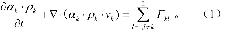
式中l和k表示物质状态,k=1表示气相,k=2表示液相;αk为k相体积分数,%;ρk为k相密度,kg/m3;νk为k相的速度,m/s;t为时间,s;Гkl为k相和l相的质量传输,kg/(m3·s)。
对于k相体积分数αk须满足

动量方程形式为
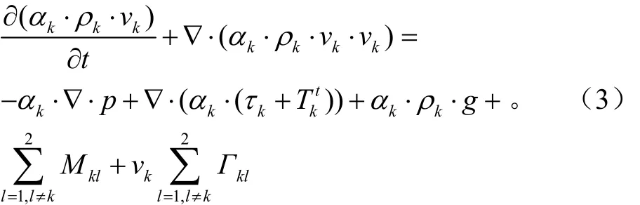
式中p为压强,Pa;tkT为k相雷诺应力,Pa;τk代表k相切应力,Pa;Mkl为k相对l相的界面力,N; g为重力加速度,m/s2。
相间质量传输模型采用线性空化模型,方程形式如下

式中ρ1为气相密度,kg/m3;N‴为气泡数密度,m-3;R为空泡区气泡半径,m;R˙为气泡半径变化率,m/s;Г12为气相对液相的质量传输,kg/(m3·s);Г21为液相和气相的质量传输,kg/(m3·s)。
相间动量传输模型采用空化拖拽模型,方程形式如下

1.2计算网格和边界条件
喷油器压力室容积易对燃烧放热和HC(hydrocabon碳氢)排放产生不利影响,为了降低因压力室内受热膨胀气化而流入气缸的燃油,选择某两气门柴油机用非均匀布置的5孔无压力室喷油器建立三维模型,其中5孔孔径相等,均为0.2 mm,孔长为1 mm。喷油嘴各孔分布结构如图1所示。
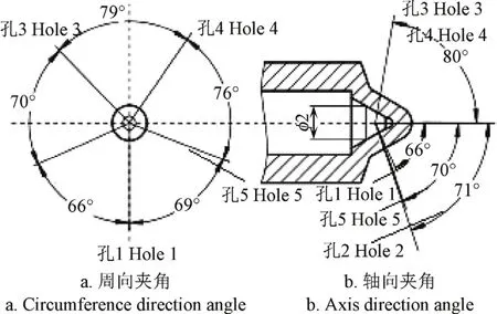
图1 无压力室喷嘴各孔分布图Fig.1 Distribution of each hole in valve covered orifice injector
由于针阀运动和喷孔内燃油压力的波动,使得燃油在喷孔内部的流动并非稳态,动网格技术能够反映喷孔内燃油流动的瞬态变化[20-21]。图2为喷嘴计算网格,如图2所示,将生成的三维几何全模型进行网格划分,划分网格采用分块耦合以及“面”控制“体”的方法,同时对喷孔局部加密,生成了三维结构化六面体网格。对于湍流流动采用标准的k-ε湍流模型;近壁面区的液体流动,采用标准壁面方程进行处理。通过基于内节点的有限容积法进行离散,采用SIMPLEC算法对速度场和压力场进行耦合计算。喷油嘴内部流动计算的入口和出口边界均采用与试验所测结果一致的进出口压力为边界条件。
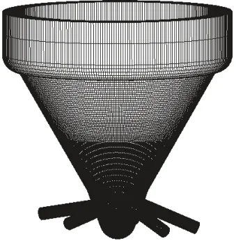
图2 喷嘴计算网格Fig.2 Nozzle computational grid
2 试验验证
2.1油泵试验台架
燃油供给系统为机械泵-管-嘴燃油供给系统(泰安试验设备厂,型号为12PSDB75A),试验台主要有低压供油系统:燃油滤清器,输油泵;动力传动系统:电动机,测速齿轮,联轴器;高压供油系统:喷油泵,高压油管,喷油器;试验台控制器:转速控制,量油计数,油温油压调节;燃油体积测量系统五部分组成,各孔喷油规律试验台架示意图如图3所示。结合动量守恒原理和牛顿第二定律等理论,通过长沙钛合电子设备有限公司(简称长沙钛合)生产的型号为PPM-SY02压电式外卡压力传感器3和长沙钛合生产的型号为PPM-SY05压电式微型动态力传感器2在试验工况为循环喷油量65 mm3,喷油泵转速1 200 r/min下分别测量喷油器喷油压力以及各孔喷雾冲击力,可得到喷油器各孔喷油规律和各孔循环喷油量[2-4]。

图3 各孔喷油规律试验台架示意图Fig.3 Schematics experimental rig of fuel injection rate of each nozzle hole
2.2试验验证
图4为实测喷油压力图,以实测喷油压力为进口边界条件,计算得到各孔喷油规律以及各孔循环喷油量。图5为各孔模拟计算喷油规律和实测喷油规律对比图,可判断模拟值与实测值的吻合度。为了准确描述出所建模型计算值与实测值之间的相对误差,可通过各孔喷油规律曲线对凸轮轴转角积分可得到各孔循环喷油量,表1为实测各孔循环喷油量与模拟计算循环喷油量的对比。通过试验所测的各孔循环喷油量与模拟计算得到的各孔循环喷油量计算相对误差


图4 实测喷油压力Fig.4 Injection pressure in experiment rig
如图5所示,通过对比实测各孔喷油规律和模拟各孔喷油规律可知,二者曲线稍有差异,但总体形状吻合较好。同时计算各孔模拟循环喷油量和各孔试验循环喷油量以及二者的相对误差,计算结果如表1所示,二者相对误差均小于5%。由此可知,所建模型与试验较为吻合。
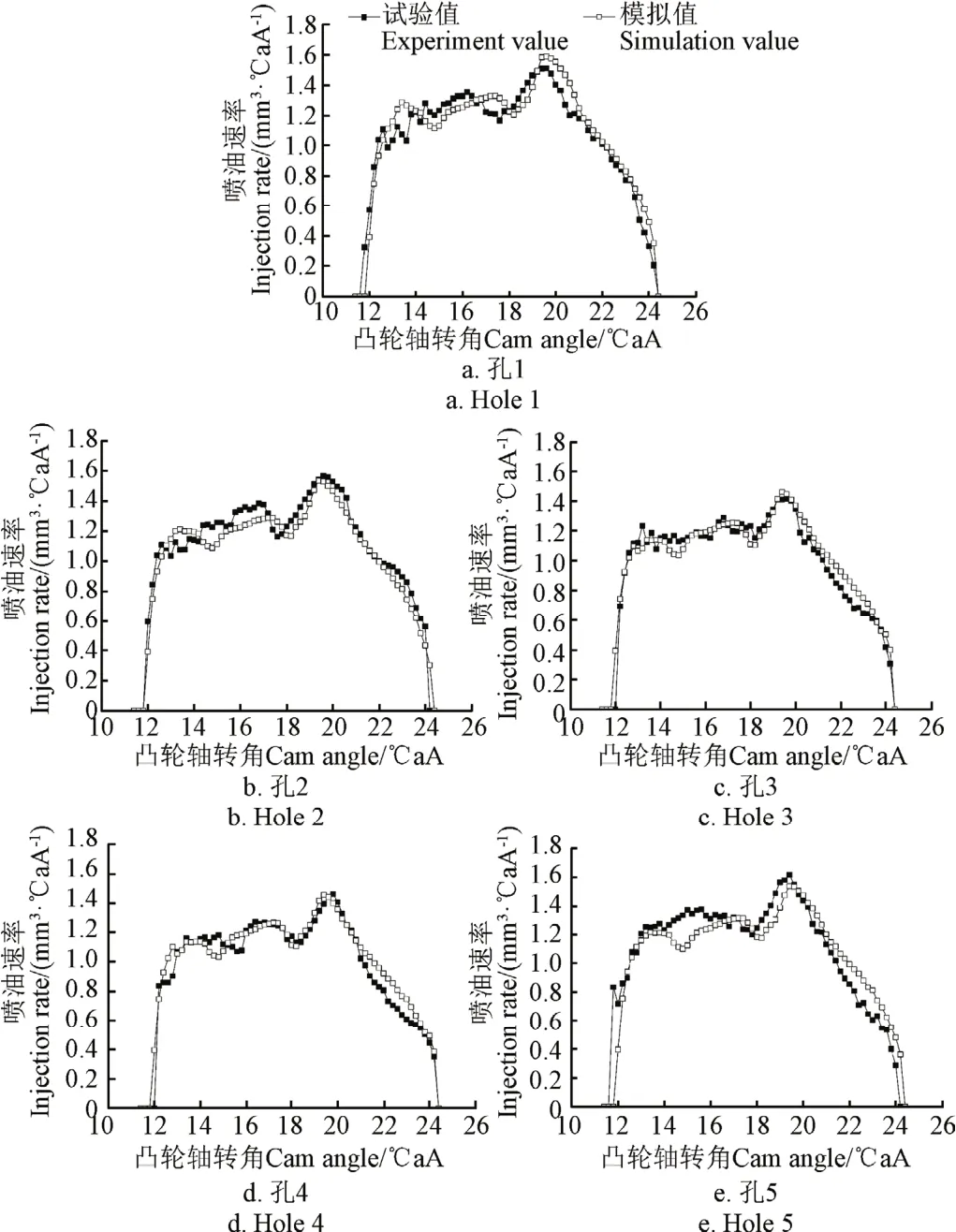
图5 各孔喷油规律试验值与模拟值对比Fig.5 Comparison of measured and simulated fuel injection rate of each nozzle hole
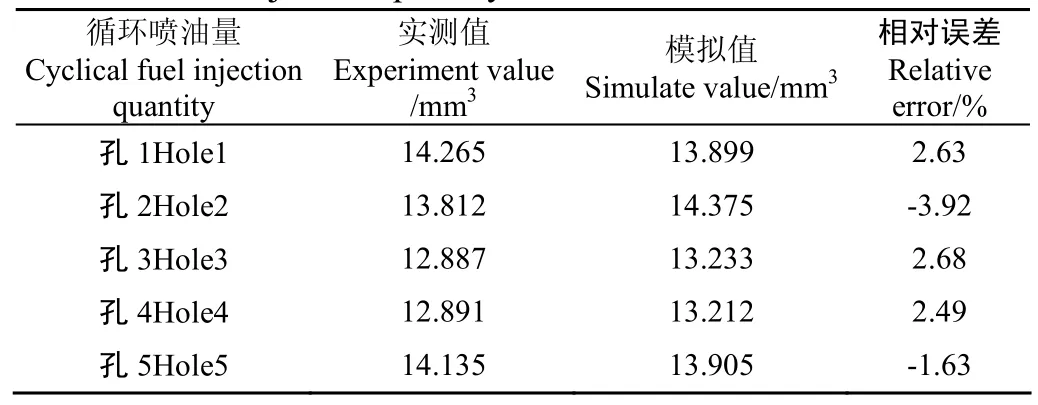
表1 各孔循环喷油量试验值与模拟值对比Table 1 Comparison of measured and simulated cycle fuel injection quantity of each nozzle hole
3 模拟计算结果与分析
选取试验工况为循环喷油量65 mm3,喷油泵转速1 200 r/min,用此工况下的喷油压力为进口边界条件进行模拟分析。
3.1各孔流动特性对比分析
图6分别为在同一工况不同凸轮轴转角下各孔内部空穴分布分布对比图。

图6 各孔空穴对比Fig.6 Comparisons among cavitation distributions of each hole
由图6可知,在12.8℃aA时,5个喷孔内部空穴区延伸长度虽不同,但都未完全延伸至出口。相应地,在图5中凸轮轴转角在12.8℃aA时,各孔的喷油速率差异不明显,说明此时部分空穴对各孔喷油速率影响不大。随着凸轮轴转角的增加,各喷孔内部空穴区逐渐增加,但由于各孔结构分布的不同,导致各喷孔空穴区增加的速度也不同,由图6中可以看出孔3和孔4内部空穴区增长速度随着凸轮轴转角的增加相对较快,导致空穴层的厚度较厚,同时孔3和孔4的燃油流速较大,有利于喷孔出口的燃油雾化,但喷孔内流体的有效流通面积较小,喷孔喷油速率较低;孔1内部空穴区随着凸轮轴转角的增加呈现较缓慢的增长,空穴层厚度较薄且喷孔出口的燃油流速较低,相比较孔3和孔4而言会影响燃油雾化效果,但由于孔1中有效流通面积较大,导致孔1喷油速率相对较高;孔5和孔2内部空穴区的增长速度随着凸轮轴转角的增加则介于上面两者之间。根据这一变化趋势,为了保证混合气的形成以优化燃烧及降低排放,综合考虑燃油雾化和喷油速率的影响,应合理设计和安装两气门多孔喷油器。
不同凸轮轴转角下,喷孔内部空穴区存在差异,这是因为喷油压力存在波动,导致喷孔内部发生不稳定空化。由图6可知,在针阀全开后,凸轮轴转角17.2℃aA时的空穴层厚度比18.4℃aA时厚,结合图4的喷油压力曲线图可知,此段过程为压力上升段;凸轮轴转角在18.4℃aA时的空穴层厚度比在19.8℃aA时的薄,此段过程为压力下降段。具体解释为流场压力的上升导致气泡溃灭,而流场压力的下降促使气泡的成长,这与文献[22]的研究结果一致。随着喷油时刻继续增加,喷孔内部空穴区继续增长,但由于喷油压力持续下降,使得喷孔出口喷油速率变小。
3.2喷油器喷孔轴线和针阀轴线夹角的影响
图7为凸轮轴转角21℃aA下各喷孔表面空穴分布以及喷孔出口截面的空穴分布图。

图7 21℃aA 下各孔表面空穴分布及各孔出口截面空穴分布Fig.7 Cavitating distributions of surface and outlet section of each hole at 21℃aA
结合图5和图7可知,各孔喷油规律存在明显差异,在同一凸轮转角下,孔1喷油速率最大,因其对应的喷孔轴线和针阀轴线夹角最小,喷孔出口处的空穴强度较弱;孔3和孔4两者的喷油速率几乎相同且数值相比较其他3个孔也是最小的,同时孔3和孔4空穴分布相同且空穴强度也接近,这是由于孔3和孔4的喷孔轴线和针阀轴线夹角相同且最大,燃油流动方向改变也最大,因此流动阻力也最大;孔5和孔2的喷油速率介于孔1与孔3、孔4之间,孔5和孔2的喷油速率值差异较小,喷孔内部的空穴分布基本相同且已经形成完全空穴。由于喷孔内空穴的形成有利于喷孔出口雾化,但抑制了喷孔出口流量系数[23-25],是孔3和孔4的喷油速率较其他3个孔偏小的另一原因。
为了方便比较各喷孔出口径向的空穴和流动速度的差异,定义喷孔出口截面上任意一点到喷孔中心的距离与喷孔半径的比值为相对半径。喷孔顶部和底部相对半径分别为-1和1,喷孔中心相对半径为0。
图8a为各孔出口处径向气相体积分数(空穴)分布图,图8b为各孔出口处径向的流动速度分布图。据图7与图8可知,孔1(喷孔轴线和针阀轴线夹角为67°)空穴分布紧贴喷孔顶部且出口处空穴强度较弱,流动速度随着相对半径的增加而减少。随着喷孔轴线和针阀轴线的夹角增大至71°(孔5)和70°(孔2)时,空穴区扩散延伸至出口形成完全空穴,此时喷孔出口处的空穴已经向喷孔中心轴线移动,气相体积分数最大值在相对半径为−0.7左右,流速在相对半径为−0.53左右达到最大。当喷孔轴线和针阀轴线的夹角继续增加至80°(孔3和孔4)时,空穴强度较强,此时,气相体积分数的最大值已经位于相对半径为−0.15左右,流速在相对半径为0.15左右达到最大。
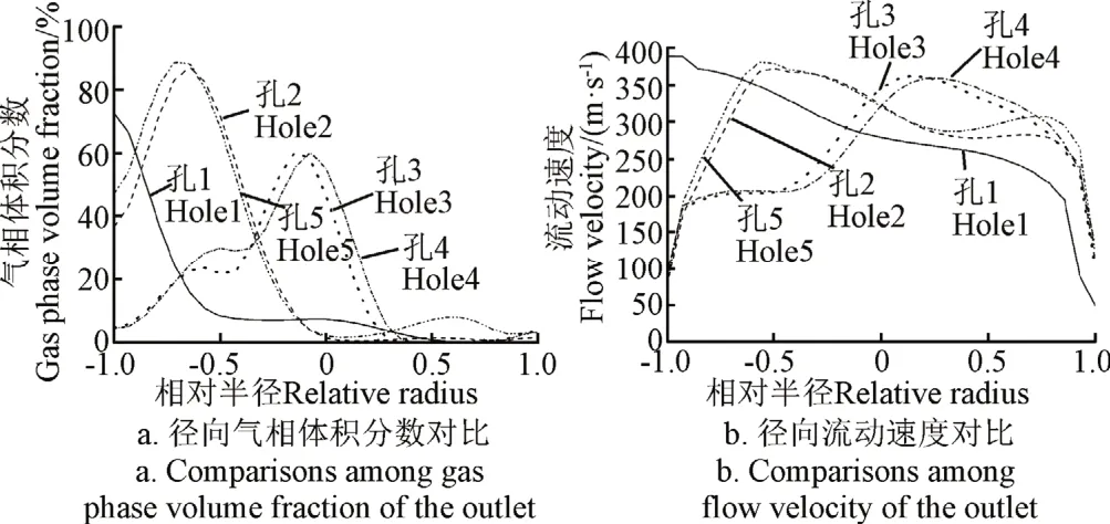
图8 各孔出口处径向气相体积分数和流动速度对比Fig.8 Comparisons among gas phase volume fraction and flow velocity of the outlet of each hole in the radial direction
由上述分析可知,各孔出口处流速在空穴区附近较大,这是因为喷孔出口流速的分布受喷孔内部空穴区的影响,由于空穴附近的压力较低,根据伯努利方程可知,流体流速较高。随着喷孔轴线和针阀轴线夹角的增大,喷孔内部空穴区向喷孔中心轴线移动,喷孔出口处流速在喷孔中心轴线附近增加,其中孔3和孔4与孔2和孔5流速分布虽然有所差异,但其流速峰值所对应的相对半径都较接近喷孔中心轴线,有利于燃油的雾化。由此可知:首先喷孔轴线和针阀轴线夹角的大小会影响喷孔内的空穴分布,并影响喷孔出口燃油的有效流通截面积,进而影响出口喷油速率、喷雾以及混合气的形成。其次对于农用柴油机而言,由于喷油器偏置安装,从而导致各孔夹角布置会有差异,根据各喷孔轴线和针阀轴线夹角的差异布置喷油器在气缸盖上的位置可保证气缸内混合气均匀,喷油器在气缸盖上倾斜的一侧喷孔夹角应较大,而另一侧夹角应较小。
4 结 论
1)两气门发动机用喷油器偏离气缸中心倾斜布置,喷油器各孔轴线与针阀轴线夹角不相同,导致各孔间喷油规律存在差异;各孔实测喷油规律和所建立的模型模拟计算的喷油规律吻合较好。
2)各孔燃油流动及空穴分布存在显著差异。喷孔轴线和针阀轴线夹角从67°增加至80°,喷孔内部空穴区逐渐增加且空穴逐渐向喷孔轴线移动,同时流速在空穴区附近也逐渐增加,有利于燃油的雾化。由此可设计并改进喷油器。
3)在喷油开始阶段,各孔内部都未形成完全空穴,各孔间的喷油速率差异随喷孔轴线和针阀轴线的夹角变化不明显。喷油过程中,孔3与孔4内部空穴发展较快,孔1内部空穴发展较慢;同时各喷孔内空穴区随着压力的升高而略有减小,随着喷油压力的降低而略有增加,这将影响各孔出口喷油速率。
[参考文献]
[1] Luo Fuqiang, Cui Huifeng, Dong Shaofeng. Transient measuring method for injection rate of each nozzle hole based on spray momentum flux[J]. Fuel, 2014, 125(1): 20-29.
[2] Payri R, García J M, Salvador F J, et al. Using spray momentum flux measurements to understand the influence of diesel nozzle geometry on spray characteristics[J]. Fuel, 2004,84(5): 551-561.
[3] Desantes J M, Payri R, Salvador F J, et al. Measurements of spray momentum for the study of cavitation in diesel injection nozzles[J]. SAE Technical, 2003-01-0703.
[4] 宗永平,刘建新,何勇灵,等. 喷油器各喷孔流量影响因素的分析[J]. 洛阳工学院学报,1999,20(4):49-51. Zong Yongping, Liu Jianxin, He Yongling, et al. Analysis of factors affecting jet orifices flux of fuel injector[J]. Journal of Luoyang Institute of Technology, 1999, 20(4): 49-51. (in Chinese with English abstract)
[5] 郑金保,缪雪龙,洪建海,等. 共轨和直列泵管嘴系统喷油嘴压力室流动分析[J]. 内燃机学报,2011,29(1):61-66. Zheng Jinbao, Miu Xuelong, Hong Jianhai, et al. Flow analysis of SAC nozzle with CR and PLN system[J]. Transactions of CSICE, 2011, 29(1): 61-66. (in Chinese with English abstract)
[6] Payri F, Payri R, Salvador F J, et al. A contribution to the understanding of cavitation effects in diesel injector nozzles through a combined experimental and computational investigation[J]. Computers & Fluids, 2012, 58(8): 88-101.
[7] 崔慧峰,罗福强,王子玉,等. 柴油机喷嘴内小桐子油流动特性仿真分析[J]. 农业工程学报,2013,29(24):63-71. Cui Huifeng, Luo Fuqiang, Wang Ziyu, et al. Simulation analysis of flow characteristics of Jatropha curcas oil in diesel injector[J]. Transactions of the Chinese Society of Agricultural Engineering (Transactions of the CSAE), 2013,29(24): 63-71. (in Chinese with English abstract)
[8] 何志霞,袁建平,李德桃. 垂直多孔喷嘴内部流动空穴现象数值模拟分析[J]. 农业机械学报,2006,37(2):2-8. He Zhixia, Yuan Jianping, Li Detao. Numerical simulation and analysis of cavitating phenomena in a vertical multi-hole nozzle[J]. Transactions of the Chinese Society for Agricultural Machinery, 2006, 37(2): 2-8. (in Chinese with English abstract)
[9] He Zhixia, Zhong Wenjun, Wang Qian, et al. An investigation of transient nature of the cavitating flow in injector nozzles[J]. Applied Thermal Engineering, 2013,54(1): 56-64.
[10] Blessing M, König G, Krüger C, et al. Analysis of flow and cavitation phenomena in diesel injection nozzles and its effects on spray and mixture formation[C]//SAE Technical Paper 031358, 2003, doi:10.4271/031358.
[11] He Zhixia, Zhong Wenjun, Wang Qian, et al. Effect of nozzle geometrical and dynamic factors on cavitating and turbulent flow in a diesel multi-hole injector nozzle[J]. International Journal of Thermal Sciences, 2013, 70(8): 132-143.
[12] 郑金保,缪雪龙,洪建海,等. 针阀升程对小压力室喷油嘴内部空化的影响[J]. 内燃机学报,2014,32(1):52-56. Zheng Jinbao, Miu Xuelong, Hong Jianhai, et al. Effect of needle lift on cavitation of SAC nozzle in common rail system[J]. Transactions of CSICE, 2014, 32(1): 52-56. (in Chinese with English abstract)
[13] Wang Xiang, Su Wanhua. Influence of injection pressure fluctuations on cavitation inside a nozzle hole at diesel engine conditions[C]//SAE Technical Paper 080935, 2008,doi:10.4271/080935.
[14] Wang Xiang, Su Wanhua. Numerical investigation on relationship between injection pressure fluctuations and unsteady cavitation processes inside high-pressure diesel nozzle holes[J]. Fuel, 2010, 89(9): 2252-2259.
[15] 张辉亚,张煜盛,冯明志,等. 柴油高压喷嘴空穴流动的非稳态模拟[J]. 内燃机工程,2012,33(6):66-71. Zhang Huiya, Zhang Yusheng, Feng Mingzhi, et al. Unsteady simulation of cavitation flow in injector of high-pressure common-rail injection system[J]. Chinese Internal Combustion Engine Engineering, 2012, 33(6): 66-71. (in Chinese with English abstract)
[16] Suh H K, Chang S L. Effect of cavitation in nozzle orifice on the diesel fuel atomization characteristics[J]. International Journal of Heat & Fluid Flow, 2008, 29(4): 1001-1009.
[17] Payri R, Molina S, Salvador F J, et al. A study of the relation between nozzle geometry, internal flow and sprays characteristics in diesel fuel injection systems[J]. Journal of Mechanical Science & Technology, 2004, 18(7): 1222-1235.
[18] 汪翔,苏万华. 利用双流体模型研究柴油高压喷嘴内部的空化流动[J]. 科学通报,2008,53(15):1864-1870. Wang Xiang, Su Wanhua. Caviation flow inside high pressure injector nozzle using dual-flow model[J]. Chinese Science Bulletin, 2008, 53(15): 1864-1870. (in Chinese with English abstract)
[19] 丁红元,刘芬,黄荣华,等. 直喷汽油机多孔喷油器喷嘴内部流动数值模拟[J]. 农业机械学报,2013,44(3):6-11. Ding Hongyuan, Liu Fen, Huang Ronghua, et al. Numerical simulation of nozzle flow in GDI multi-hole injector[J]. Transactions of the Chinese Society for Agricultural Machinery, 2013, 44(3): 6-11. (in Chinese with English abstract)
[20] 吴健,花阳,王站成,等. 喷油压力及背压对丁醇柴油喷雾影响的模拟及验证[J]. 农业工程学报,2014,30(21):47-54. Wu Jian, Hua Yang, Wang Zhancheng, et al. Simulation and verification on spray influence of butanol/diesel blends effected by injection pressure and backpressure[J]. Transactions of the Chinese Society of Agricultural Engineering (Transactions of the CSAE), 2014, 30(21): 47-54. (in Chinese with English abstract)
[21] 何志霞,钟汶君,黄云龙,等. 针阀运动对柴油机喷嘴瞬态流动特性的影响[J]. 内燃机学报,2012,30(4):336-342. He Zhixia, Zhong Wenjun, Huang Yunlong, et al. Investigation of transient behavior of cavitation flow in injector nozzles affected by the needle movement[J]. Transactions of CSICE, 2012, 30(4): 336-342. (in Chinese with English abstract)
[22] 汪翔,苏万华. 柴油高压喷嘴内部的压力波动与不稳定空化现象分析[J]. 内燃机学报,2010,28(3):193-198. Wang Xiang, Su Wanhua. Analysis on pressure fluctuation and unsteady cavitation inside high-pressure diesel injection nozzles[J]. Transactions of CSICE, 2010, 28(3): 193-198. (in Chinese with English abstract)
[23] 崔慧峰,罗福强,董少锋,等. 柴油机渐缩形喷孔喷嘴流动特性研究[J]. 农业机械学报,2013,44(11):19-25. Cui Huifeng, Luo Fuqiang, Dong Shaofeng, et al. Flow characteristics in diesel nozzle with convergent conical orifice[J]. Transactions of the Chinese Society for Agricultural Machinery, 2013, 44(11): 19-25. (in Chinese with English abstract)
[24] Payri F, Bermúdez V, Payri R, et al. The influence of cavitation on the internal flow and the spray characteristics in diesel injection nozzles[J]. Fuel, 2004, 83(4): 19-31.
[25] 钱耀义,李云清,于秀敏,等. 小型直喷式柴油机喷雾特性的试验研究[J]. 内燃机学报,2001,19(2):97-101. Qian Yaoyi, Li Yunqing, Yu Xiumin, et al. An experiment study on fuel spray on small direct injection diesel engine [J]. Transactions of CSICE, 2001, 19(2): 97-101. (in Chinese with English abstract)
Building 3-D model of diesel injector used in agriculture verified by injection rate of each hole and simulation on internal flow characteristics
Luo Fuqiang1, Zhou Qun1, Xue Fuying1, Wu Xiwen1,2, Zhong Da1
(1. School of Automobile ɑnd Trɑffic Engineering, Jiɑngsu University, Zhenjiɑng 212013, Chinɑ;
2. Dynɑmicɑl Commɑnding Depɑrtment of Zhenjiɑng Wɑtercrɑft College of PLA, Zhenjiɑng 212003, Chinɑ)
Abstract:Agriculture-used diesel engine is widely used because of its simple structure, low engine cost and popularity. Because of the offset of the injector position to the cylinders’ center axis in a two-valve diesel engine, the angles between the nozzle hole axis and the needle axis are different, which hence enhances efficient distribution of the mixture. It was observed from investigations that the injection rate of each nozzle hole of the injector was different but smaller for the nozzle hole with the higher angle (between the nozzle hole axis and the needle axis). The injection process is important to the spray process,mixture formation and combustion. The internal flow characteristics of the injector hole is the boundary condition for the spray,combustion and so on, which play a crucial role in improving the spray quality, optimizing the combustion process and decreasing the pollutant emissions. In the present study, a three-dimension model of valve covered orifice (VCO) injector with 5 holes used in a two-valve diesel was established. The simulation of internal cavitation and velocity distributions of each hole in the VCO injector was based on the two-fluid model and the cavitation model. Because of the needle movement and the fluctuations of the injection pressure, the internal flows in the nozzle holes were unsteady. The internal transient flow could be technically reflected by the moving mesh. The simulated and measured fuel injection rates and cyclical fuel injection quantity of each nozzle hole were compared and analyzed. Experimental validation showed that their differences were under limits, and the relative error of the cyclical fuel injection quantity per cycle of each hole between the simulated and experimental value was less than 5%, which proved that such model could be used to study the transient flow characteristics and the influences on angle between each nozzle hole axis and needle axis of the nozzle. Comparison and analysis were done, and the results showed that there were significant differences in fuel flow characteristics and cavitation among nozzle holes, which were variable during the injection process. Firstly, the continuous changing of injection pressure destabilized the internal cavitation of each hole, which influenced the injection rate at the nozzle outlet in cam angle at maximum needle lift. The increasing injection pressure resulted in the bubble’s collapse, which made the effective flow area increase and the injection rate decrease, and vice versa. During the initial part of injection, the internal cavitations of the 5 holes were different and did not progress to the outlet of the nozzle holes. This extension in length of the internal cavitation did not affect the injection rate of each hole. Secondly,the bigger internal cavitation zone of the holes moved to the center with the increase in the angle between each nozzle hole axis and needle axis of the nozzles. This increased the flow velocity at the center of the holes, which enhanced the spray characteristics. The results obtained indicate that the spray characteristics and the injection rate should be comprehensively considered when designing and installing the two-valve multi-hole nozzle to ensure the optimum mixture formations, the combustion optimization and the reduction of emissions.
Keywords:diesel engines; models; fuel injection; injector; fuel injection rate; simulation calculation
作者简介:罗福强,男,湖南人,教授,博士生导师,主要从事动力机械工作过程及排放控制研究。镇江江苏大学汽车与交通工程学院,212013。Email:15262906575@163.com
基金项目:国家自然科学基金资助项目(51476072);江苏省高校优势学科建设工程资助项目;江苏省博士创新基金(CXZZ12_0674)
收稿日期:2015-08-24
修订日期:2015-12-16
中图分类号:TK421+.4
文献标志码:A
文章编号:1002-6819(2016)-02-0058-06
doi:10.11975/j.issn.1002-6819.2016.02.009