Entrance and Exit Defects During Coarse Pitch Orbital Drilling of Carbon Fiber Reinforced Plastic Plates
2016-02-09ang
, , ang,
1. College of Mechanical and Electrical Engineering, Nanjing College of Information Technology, Nanjing 210046, P.R. China;2.College of Mechanical and Electrical Engineering, Nanjing University of Aeronautics and Astronautics, Nanjing 210016, P.R. China 3.School of Mechanical Engineering, Nanjing Institute of Technology, Nanjing 211167, P.R. China
Entrance and Exit Defects During Coarse Pitch Orbital Drilling of Carbon Fiber Reinforced Plastic Plates
ShanYicai1,2,*,HeNing2,LiLiang2,ZhangTing3
1. College of Mechanical and Electrical Engineering, Nanjing College of Information Technology, Nanjing 210046, P.R. China;2.College of Mechanical and Electrical Engineering, Nanjing University of Aeronautics and Astronautics, Nanjing 210016, P.R. China 3.School of Mechanical Engineering, Nanjing Institute of Technology, Nanjing 211167, P.R. China
(Received 2 December 2015; revised 7 June 2016; accepted 29 June 2016)
Formation of entrance and exit defects in coarse pitch orbital drilling (CPOD) of carbon fiber reinforced plastic (CFRP) plates was investigated. Deep observation on entrance and exit morphology shows tear and burr are typical defects. Meanwhile, tear is more obvious than burr, and more entrance tears emerge than exit tears. As one of the major causes of entrance and exit defects in CPOD, cutting forces were substaintially studied by contrast experiments. Then, the effect of cutting parameters on entrance and exit tear was qualitatively analyzed through a single factor test. Experiment results indicate that the variation of rotation speed has little influence on entrance and exit tear. Increasing tangential feed per tooth can enlarge entrance tear, but bring little effect on exit tear. By increasing axial feed pitch, the hole entrance and exit show severe tear. When revolution radius grows bigger and bigger, entrance and exit tear firstly decreases, and then increases. Finally, the models of tear and delamination during CPOD of CFRP were established, the formation mechanisms of entrance and exit defects were revealed, and the control strategies were accordingly put forward.
carbon fiber reinforced plastics (CFRP); coarse pitch orbital drilling (CPOD); entrance and exit defects; formation mechanism
0 Introduction
The increased usage of composite materials in aero structure components is one of the important indicators to appraise modern aircraft advancement[1]. Among various composite materials, CFRP is widely used in aerospace industry, which has good mechanical and adhesive properties. However, its heavy usage also raises the demands of high quality and precision of secondary machining hole. When machining such material by push drilling (PD), excessive axial force and high tool wear often bring about delamination and tear at the hole entrance and exit. Hence, it is urgent to minimize axial force and improve its distribution, finally eliminate defects during CFRP hole fabricate[2-6].
Scholars have research on PD of CFRP in the aspect of cutting mechanism, drill bit structure, cutting parameters optimization, and so on. Lachaud et al.studied the distribution of PD force along cutting edge, and found the force was uniform along chisel edge and main cutting edge[7]. Tsao et al.machined CFRP with various drill bits. The experimental results showed that feed and drill size had the greatest influence on axial force, and the axial force of core-saw drill was the highest[8-9]. Krishnaraj et al.analyzed the influence of process parameters on delamination during PD of CFRP[10]. Wonm et al. studied the effect of pilot hole on PD force, and found that it could reduce axial force by 50%[11]. Many scholars put forward a kind of variable feed strategy to inhibit exit defects[12-14]. Tao et al.investigated the effect of exit back-up on exit delamination, and found that exit back-up could raise the critical value of thrust force[15].
The above research achievements have played an important role in promoting PD technique development of CFRP. However, PD has many inherent defects as semi-enclosed cutting, high tool wear, chip removal difficulty, and fixed size hole making, and therefore PD fails to meet the demand of high precision and efficiency hole-making. Developing new hole-making technologies based on cutting mechanism is a good choice.
In the 1990s′, foreign scholar first proposed a new hole-making method by milling (i.e. orbital drilling, OD)[16]. Compared with PD, this method could significantly reduce axial force, and also have advantages of little tool wear, easy chip removal and heat dissipation, good machining accuracy, and so on. It has a good application prospect in aviation manufacturing[17-20]. Recently, the new hole-making process is becoming a research hotspot. Wang et al.conducted contrast experiment of OD and PD of CFRP, and discovered the reduction of cutting temperature worked as the main reason to improve exit defect in OD[18]. Shigehiko et al. studied the influence of revolution speed on cutting temperature, and discovered the increase of revolution speed and the adoption of compressed air would help to lower cutting temperature in OD[21]. Wang investigated the influence of cutting parameters and tool wear on cutting force, and analyzed the changes of diameter tolerance, roundness error, and surface roughness[22]. Denkena et al. analyzed the influence of axial feed and tangential feed on cutting force and hole precision[23].
Although a large amount of research achievements have been gained in OD of CFRP, research focuses on small pitch orbital drilling (SPOD), which is subject to mechanism study and machining devices. Small pitch feed could decrease machining efficiency, and need higher revolution speed. Especially in robotic hole-making systems, SPOD may impact machining performance of the whole system[24]. Therefore, Shan et al. proposed a new machining method as coarse pitch orbital drilling (i.e. CPOD)[25]in which axial feed pitch was greater than or equal to 0.5 mm. However, the increase of axial feed pitch would enlarge cutting force, and accelerate tool wear, which lead to different hole defects from PD and SPOD. The paper attempts to study defect type and formation reason during CPOD of CFRP, in order to better inhibit entrance and exit defects.
1 Tests of Entrance and Exit Defects in CPOD
The tests of entrance and exit defects were performed on UPC710 machining center with a spindle of 50 kW. The maximum spindle speed was 18 000 r/min and the maximum feed rate was 50 m/min. Cutting parameters of CPOD were designed in Table 1. Rotation speednswas set as 3 000, 4 500, 6 000 r/min. Tangential feed per toothfztwas set as 0.03, 0.04 and 0.05 mm. Axial feed pitchPwas set as 0.5, 1, and 1.5 mm, and revolution radiusewas set as 1, 2 and 3 mm. The test of CPOD used two solid carbide end mills with four teeth and coating TiAlN. The diameters of the two end mills were 8 mm and 6 mm,respectively.

Table 1 Cutting parameters and experimental condition in CPOD
The test materials were comprised of T300 carbon fiber and 3234 epoxy resin. The stacking sequence of the laminate is [0/90]8S.The CFRP laminates were 15 plies with 60% fiber volume fraction. Physical photo and plain weave sketch of the CFRP laminates are shown in Fig.1. The size of the CFRP laminates was 200 mm×100 mm×3.8 mm. Chip removal by vacuum was adopted to lower temperature in cutting zone.
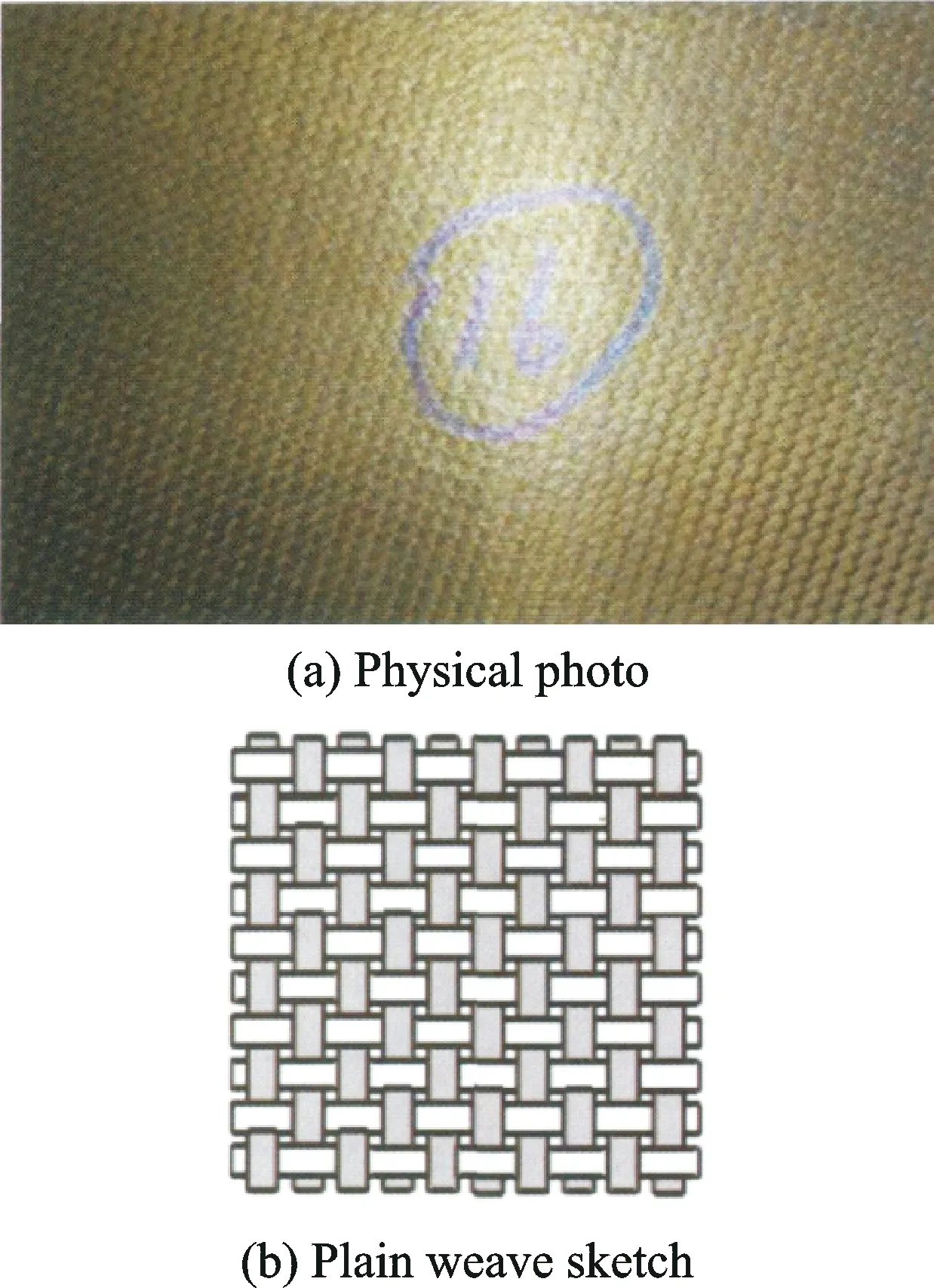
Fig.1 CFRP laminates
To analyze the impact of coarse pitch feed on cutting force and hole making defect, a contrast test of CPOD and PD was also conducted. Cutting parameters in contrast test were designed in Table 2. PD test was performed by a ∅10.2 mm solid carbide drill with two teeth and Coating TiAlN. The tools of contrast test are shown in Fig.2.
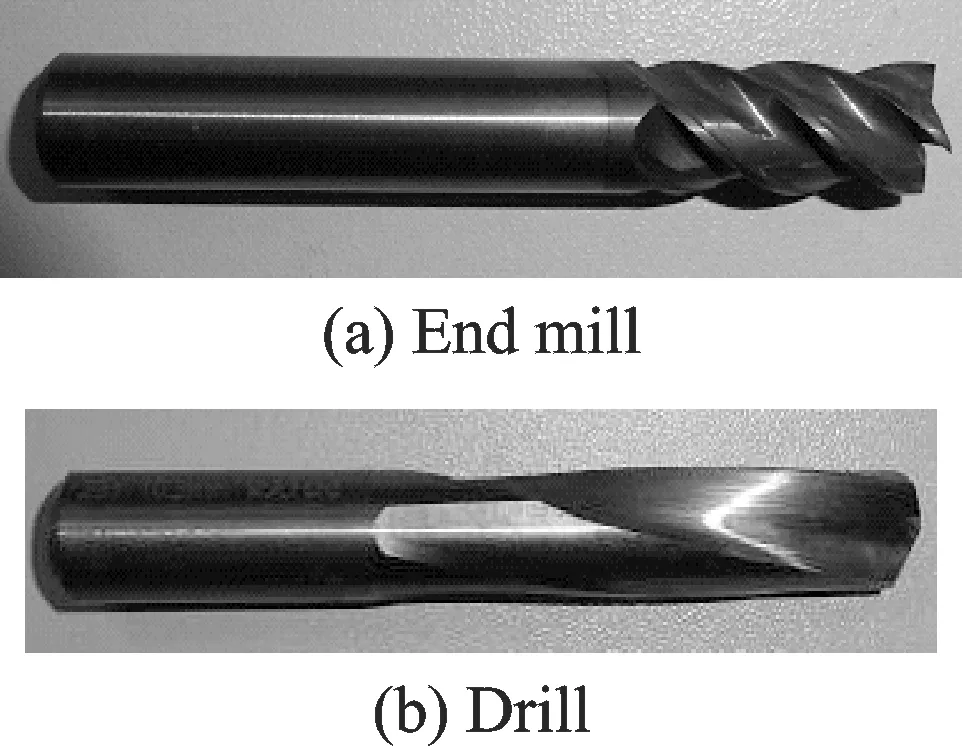
Fig.2 Tools of contrast test
Cutting force was measured using 3-component dynamometer, Kistler 9265B, and 5019 Kistler charge amplifier. Entrance and exit defects were observed by tool microscope. To display entrance and exit defects clearly, image zooming technique was used in morphology pictures processing. Therefore, holes with the same diameter might show different sizes in various pictures.

Table 2 Cutting parameters in contrast test
2 Entrance and Exit Morphology Observation and Cutting Force Analysis in CPOD
2.1 Observation of entrance and exit morphology
Fig.3 gives entrance and exit morphology when a ∅10.2 mm hole was produced by CPOD using a ∅8 mm end mill withnsof 3 000 r/min,fztof 0.05 mm, andPof 0.5 and 1.5 mm. As can be seen from Fig.3(a), there is some exit tear. Parallel torn cracks on the surface layer could be observed clearly, and the bottom materials are invisible. These cracks at the peripheral direction of the hole is wide enough and looks like a rectangular. From Fig.3(b), the entrance shows a certain scope of tear, and the torn materials have fallen off. The torn shape parallel to the peripheral direction of the hole looks like zigzag. The length of entrance tear is 1.82 mm, and the width is 0.656 mm. WhenPis set at 1.5 mm, entrance and exit tear are obviously serious as shown in Figs.3(c,d). There is much exit tear and uncut materials in CPOD. The broken of uncut materials at the hole exit appears at one side of the hole, which is evidently different from the broken at the hole center in PD. Although the torn materials at the hole entrance has not fallen off, strip tore is more distinct than that in Fig.3(b).
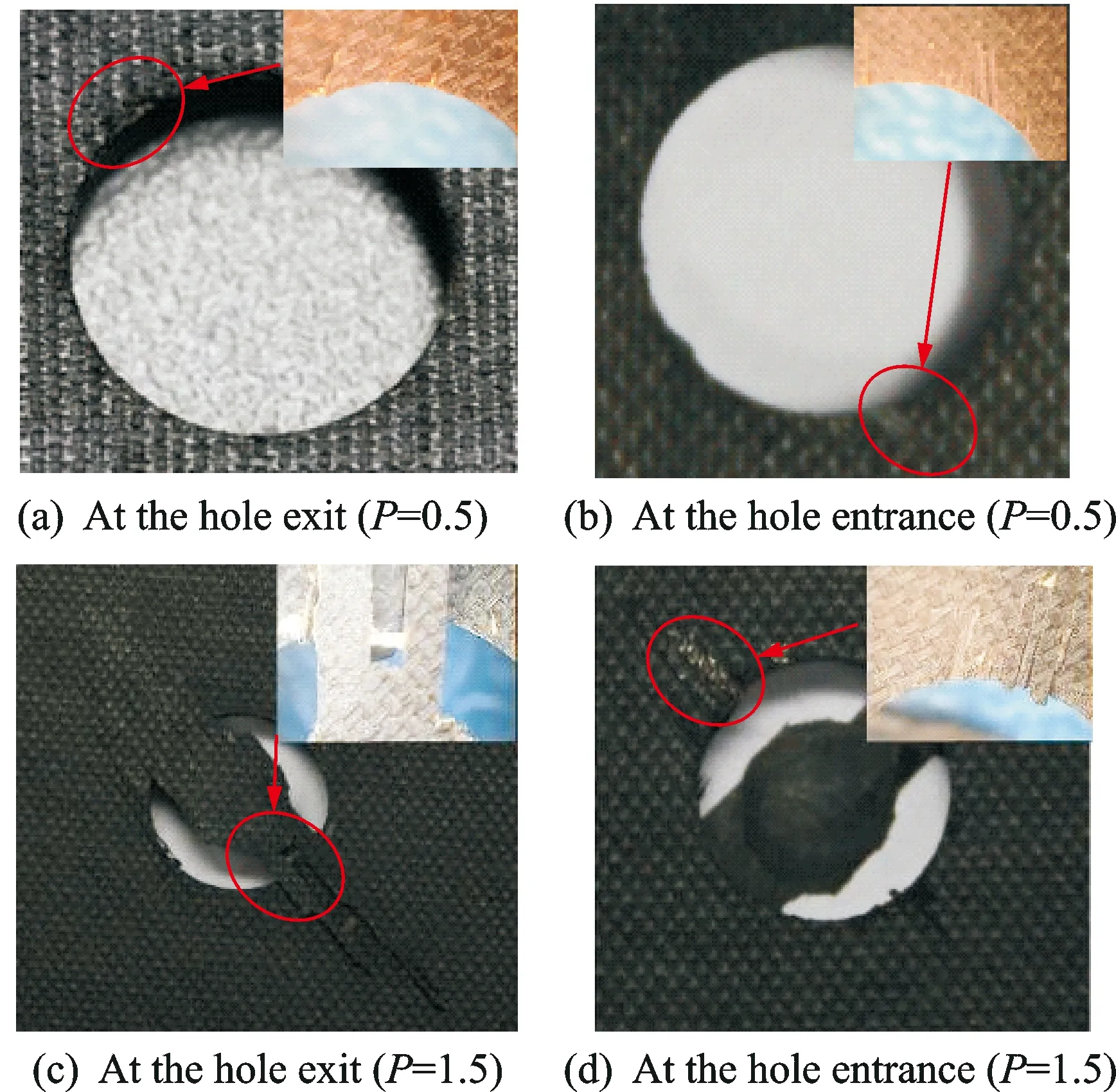
Fig.3 Entrance and exit morphology with ∅8 mm end mill
Fig.4 shows entrance and exit morphology when a ∅10.2 mm hole is produced by CPOD using a ∅6 mm end mill with rotation speednsof 3 000 r/min,fztof 0.05 mm,Pof 0.5 and 1.5 mm. In Fig.4, there is no tear and burr at the hole exit, and little tear happens at the hole entrance. Entrance tear in Fig.4(d) is more serious than in Fig.4(b).
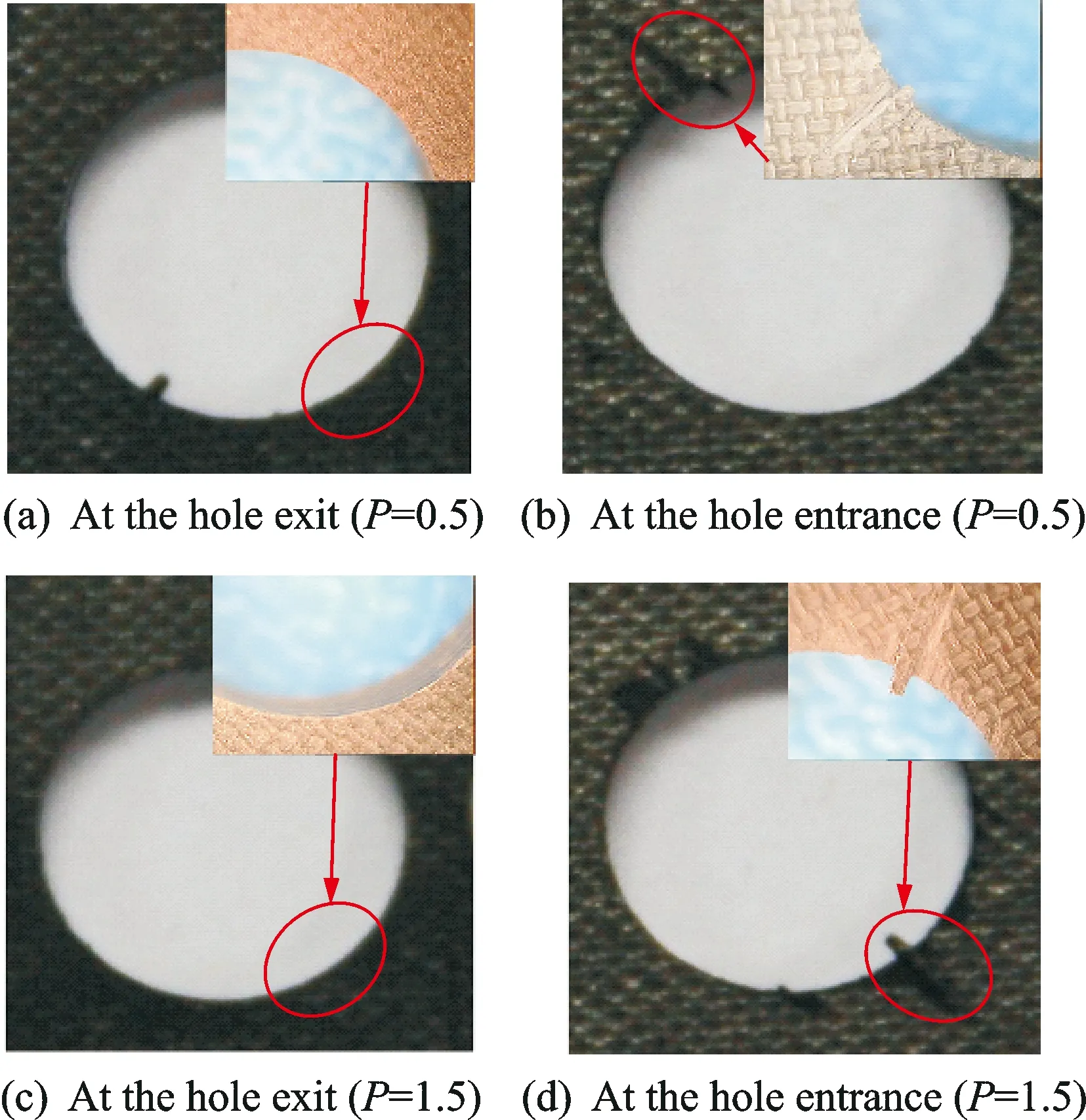
Fig.4 Entrance and exit morphology with ∅6 mm end mill
From Figs.3,4, it is easy to know that the increase ofPwould sharply worsen entrance and exit defects, and small diameter tool would contribute to restrain entrance and exit defects, and much more entrance tear emerges than exit tear. In the tests, it is also discovered that entrance and exit tear looks more serious than delamination and burr.
2.2 Analysis of cutting force
Cutting force is one of the major factors causing entrance and exit defects in CFRP. To investigate the influence of cutting force on hole making defects in CPOD, the contrast experiment was performed according to Table 2. Fig.5 shows measure values of cutting forces in CPOD and PD.
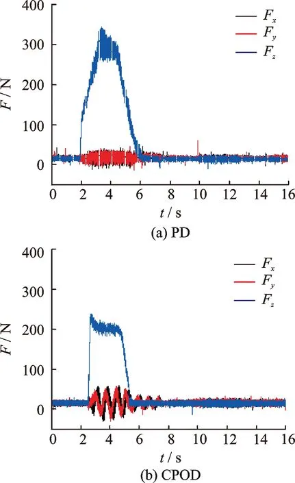
Fig.5 Cutting forces of PD and CPOD
Compared Fig.5(b) with Fig.5(a), we found that Fxand Fyin CPOD are bigger than those in PD. The axial force Fzof CPOD is about 250 N, while the value of PD is 350 N, which is significantly reduced by about 29%. As cutting speed of tool center top (TCP) is 0 during PD, hole center materials are separated from the workpiece by squeezing. However, hole bottom materials in CPOD are cut by side and front cutting edges. The difference might have impact on entrance and exit defects in CPOD.
Since axial force of CPOD mainly comes from front cutting edge, it is also observed that the amplitude of axial force in CPOD is uprising faster than that in PD. When axial feed depth of the tool is equal to axial feed per tooth, axial cutting thickness per tooth of front cutting edge remains at a constant value, and the axial force at the moment reaches the maximum. As rotating speed is much higher than revolution speed, the variation of axial feed depth from zero to the maximum is transient. In PD, chisel edge first contacts with workpiece material and main cutting edge gradually participates in cutting. The process would cause the rise in drilling axial force to slow down. The experiment result is shown in Fig.5.
3 Main Factors Affecting Entrance and Exit Tear in CPOD
Adjusting cutting parameters is the most convenient method to control cutting force. Therefore, a single factor experiment was adopted to study the influence of cutting parameters on entrance and exit tear in CPOD.
3.1 Influence ofnson tear
Fig.6 shows entrance and exit morphology when the hole is produced by CPOD of CFRP using a ∅8 mm end milling withnsof 3 000,4 500 and 6 000 r/min,fztof 0.05 mm,eof 2 mm, andPof 1 mm. Entrance torn materials fall off whenns=3 000 r/min. Whenns=4 500 r/min, entrance torn materials are still connected with the workpiece. Whenns=6 000 r/min, a small amount of burr occurs at the entrance. Under the three above rotation speeds, there is no exit tear but only little burr at the exit. In general, rotation speednshas a limited impact on entrance and exit tear.
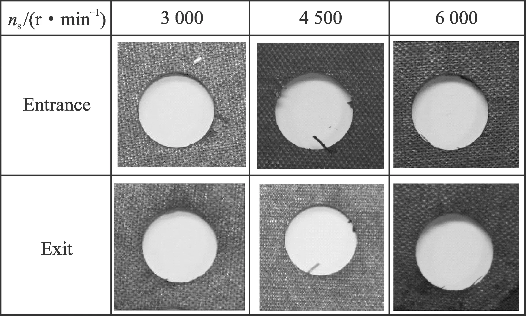
Fig.6 The influence of ns on entrance and exit tear
3.2 Influence offzton tear
Fig.7 shows entrance and exit morphology when the hole is produced by CPOD of CFRP by a ∅8 mm end milling withnsof 3 000 r/min,fztof 0.03, 0.04 and 0.05 mm,eof 2 mm, and axialPof 1 mm. From Fig.7, the increase offztcauses slight worsening of entrance tear, while exit tear does not emerge.
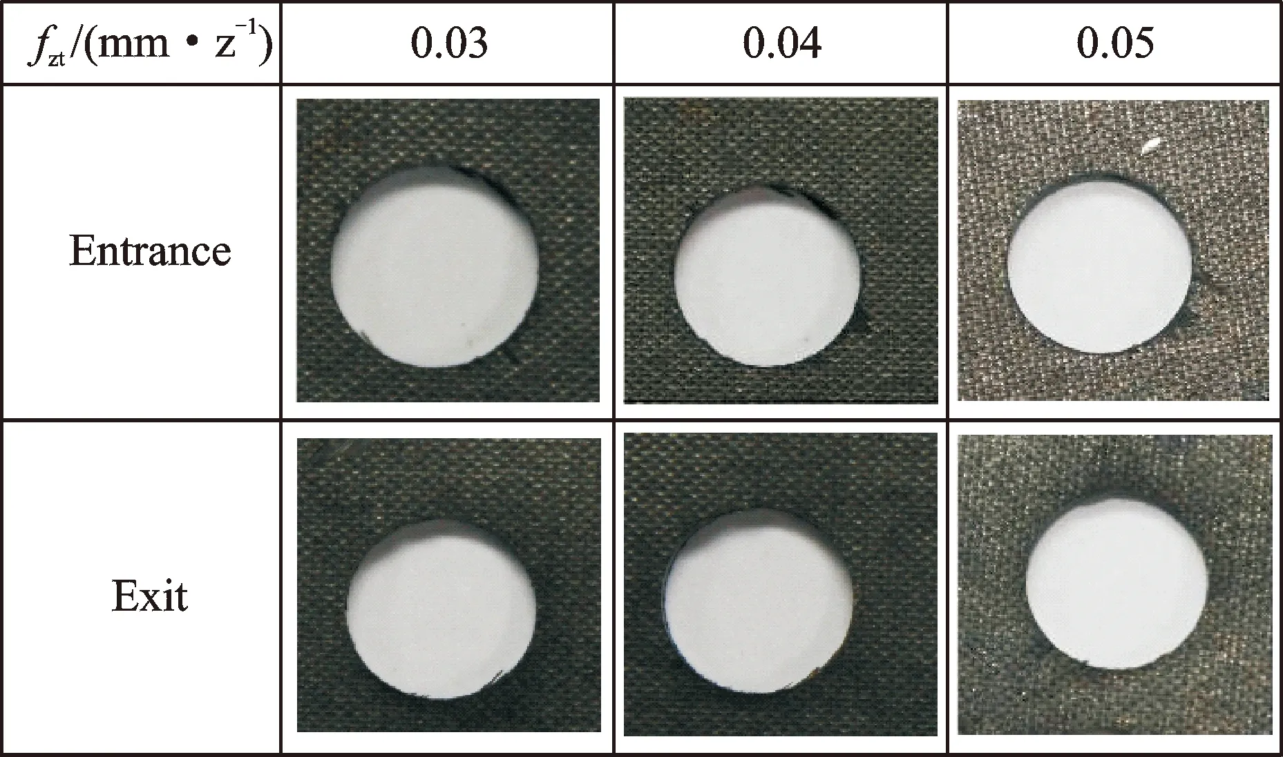
Fig.7 The influence of fzt on entrance and exit tear
For further analysis, undeformed chip model in OD is established as shown in Fig.8. Herein,fzt,maxandfza,maxdonate the maximum cutting thickness of side and front cutting edges.Pdonates axial cutting depth of side cutting edge, which is also called as axial feed pitch. According to the model,fzt,maxandfza,maxcan be calculated by Eqs.(1),(2). The two equations reveal that the increase offzthas more effect on side edge cutting than front cutting edge. Consequently, the entrance tear is more serious
(1)
(2)
whereZis the number of tool teeth,ngmeans revolution speed.
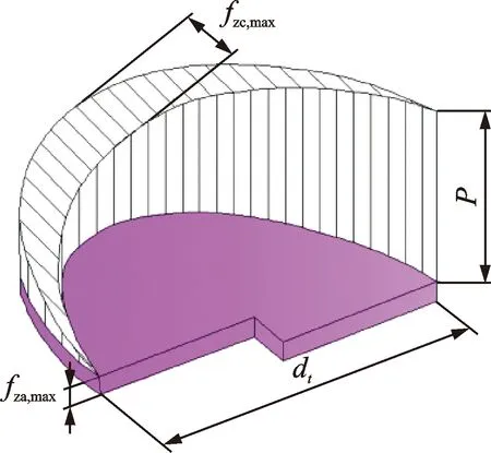
Fig.8 Undeformed chip in orbital drilling
3.3 Influence of axial feed pitchPon tear
Fig.9 shows entrance and exit morphology when the hole is produced by CPOD of CFRP using a ∅8 mm end mill withnsof 3 000 r/min,fztof 0.05 mm, revolution radiuseof 2 mm, andPof 0.5,1 and 1.5 mm. In Fig.9, entrance and exit tear shows an evident uptrend under coarse pitch feed. The reason is that when axial feed pitch increases, axial feed per tooth of front cutting edge increases according to Eq. (2), and axial cutting depth of side cutting edge is increasing at the same time. Iferemains unchanged, cutting effect of front cutting edge is increased, which leads to serious entrance and exit tear.
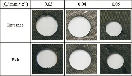
Fig.9 Influence of P on entrance and exit tear
3.4 Influence of revolution radiuseon tear
Fig.10 reveals entrance and exit morphology when the hole is produced by CPOD of CFRP using a ∅8 mm end mill withnsof 3 000 r/min,fztof 0.05 mm,Pof 1 mm, andeof 1, 2 and 3 mm. With the increase of revolution radius, entrance and exit tear decreases at first, and then increases.
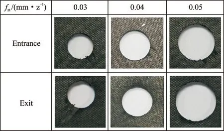
Fig.10 Influence of e on entrance and exit tear
Two cutting zones of front and side cutting edges are demonstrated in Fig. 11. Zone B refers to the region of the smallest circle. The materials in zone B are only removed by front cutting edge. Zone A represents the shadow area outside of zone B, where front and side cutting edges both participates in processing. The cutting effect in OD presents two forms. One is similar to cutting effect of drilling, the other is like the cutting effect of milling. Wheneis small, zone B becomes large accordingly, and the first cutting effect is dominant in OD. Wheneincreases, the area of zone A is accordingly enhanced, so the second cutting effect gradually plays a dominant role in OD.
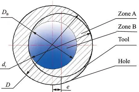
Fig.11 The influence of e on cutting zone
4 Formation Mechanism of Entrance and Exit Defects in CPOD
Similar to PD and SPOD, entrance and exit tear always accompanies with delamination during CPOD of CFRP. The following part focuses on analyzing formation mechanisms of tear and delamination in CPOD of CFRP.
4.1 Delamination and tear at the hole entrance
When the tool feeds along helical track, front cutting edge enters into cutting at first. With the tool going on feeding, side cutting edge gradually also participates in cutting. According to the relative movement trail between the tool and the workpiece, hole surface is machined by side cutting edge.
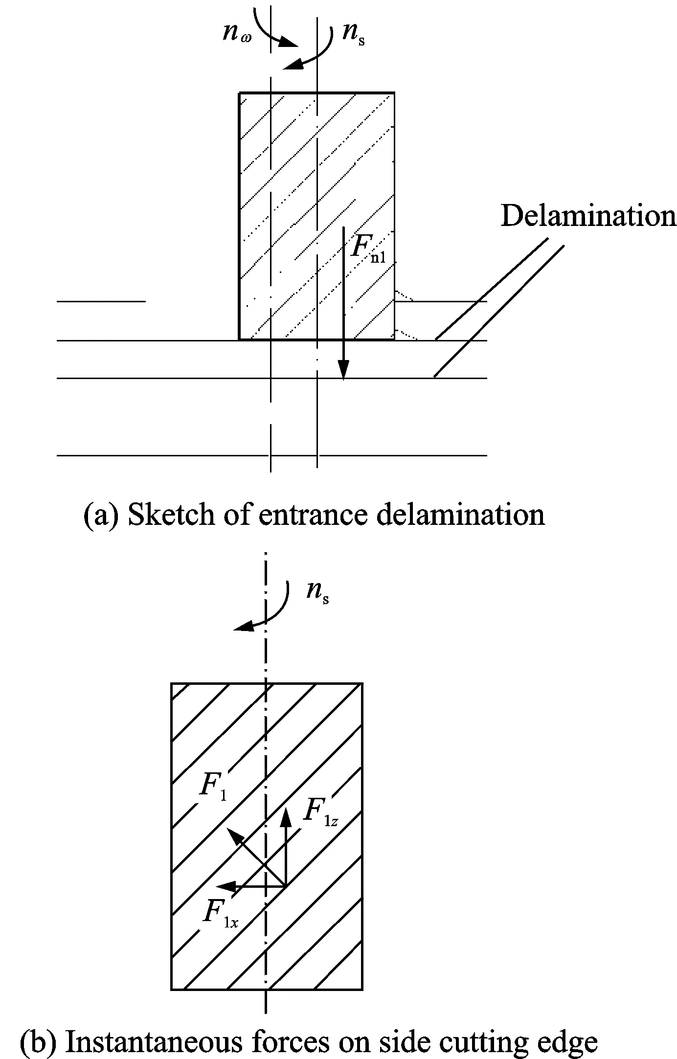
Fig.12 Formation model of entrance delamination
The moment tool cuts into workpiece, a downward normal pressure Fn1as shown in Fig.12(a) is generated by the collision between the front cutting edge of the tool and the surface layer of CFRP. Most ofFn1comes from front cutting edge. As rotation speednsis higher than revolution speedngand axial feed per toothfzais small,Fn1quickly reaches the maximum. UnderFn1, the stress and strain of the hole bottom materials changes greatly. Due to the greater thickness of the uncut materials, deformation and delamination is not distinct between the interlayers of hole bottom materials. As for hole edge, the material is cut by side cutting edge. Under tool rotation, an upward force F1Zcaused by side cutting edge acts on the part material, which is shown in Fig.12(b). If the interlayer stress caused by F1zreaches the limit value, entrance delamination would occur. However, the size of entrance delamination would become smaller and smaller when OD is going on.
Besides, the materials of entrance delamination are also acted upon by tangential component force of side cutting edge Ft1, which is shown in Fig.13. With the action of Ft1, bend deformation occurs in entrance delamination materials along the hole direction of circumference. When the deformation reaches to limit value, these bended materials would be broken, and entrance tear appears. But in PD of CFRP, main cutting edge of drill bit is gradually involved in cutting, then surface layers at the hole entrance produce downward bend deformation. In this processing method, entrance tear is difficult to be produced, which is obviously different from the situation in CPOD. Since CFRP is a hard and brittle material, cutting vibration is inevitable in CPOD of CFRP, which could increase entrance tear and burr. Therefore much, more entrance tear in CPOD emerges than in PD.
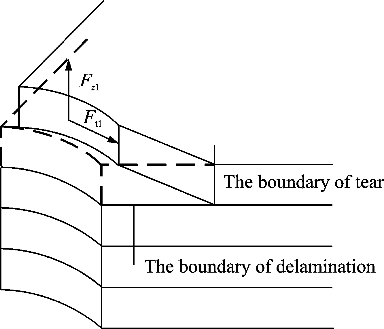
Fig.13 Formation model of entrance tear
In conclusion, entrance delamination and tear during CPOD is mainly caused by side cutting edge. To restrain entrance lamination, it is necessary to control cutting parameters of CPOD, and reduce the upping axial force resulted from side cutting edge. As for entrance tear, the tangential force resulted from side and front cutting edge should be reduced.
4.2 Delamination and tear at the hole exit
As tool gets closer to the back of CFRP laminates, downward bending deformation appears at the uncut layers of the hole bottom under the action ofFn, which is shown in Fig.14.
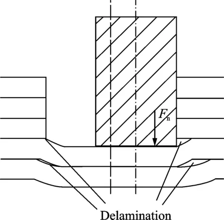
Fig.14 Formation model of exit delamination
Especially when tool comes near the last few layers,large bending deformation occurs on the uncut materials without back auxiliary support, or other material constraints. Due to the existence of revolution radius, the hole side near TCP significantly suffers from axial force Fn, so the delamination is large, while the other side far away from TCP is under little action of Fn, and accordingly the delamination is small. The large stress between layers causes model I crack to increase gradually to form exit delamination. When the machining process comes to the hole exit, the materials of hole edge are firstly cut by side cutting edge. At this moment, the hole bottom materials which are contacted with front cutting edge still have a certain thickness. If hole exit has large delamination, the situations in Figs.3(c,d) emerge.
From Figs.15,11, it could be deduced that cutting force distributing on front cutting edge firstly keeps a constant value from inside to outside in the radial direction of the hole, and then gradually decrease to zero. The materials of the hole bottom are separated from the workpiece by side cutting edge. As CFRP has low interlaminar strength, a certain scope of exit delamination occurs under axial force, although tool deviates from the central of the hole. The torn materials produce bending deformation along with the tangential direction. The surface materials of exit delamination are broken by the tangential force and forms exit tear as shown in Fig.15.
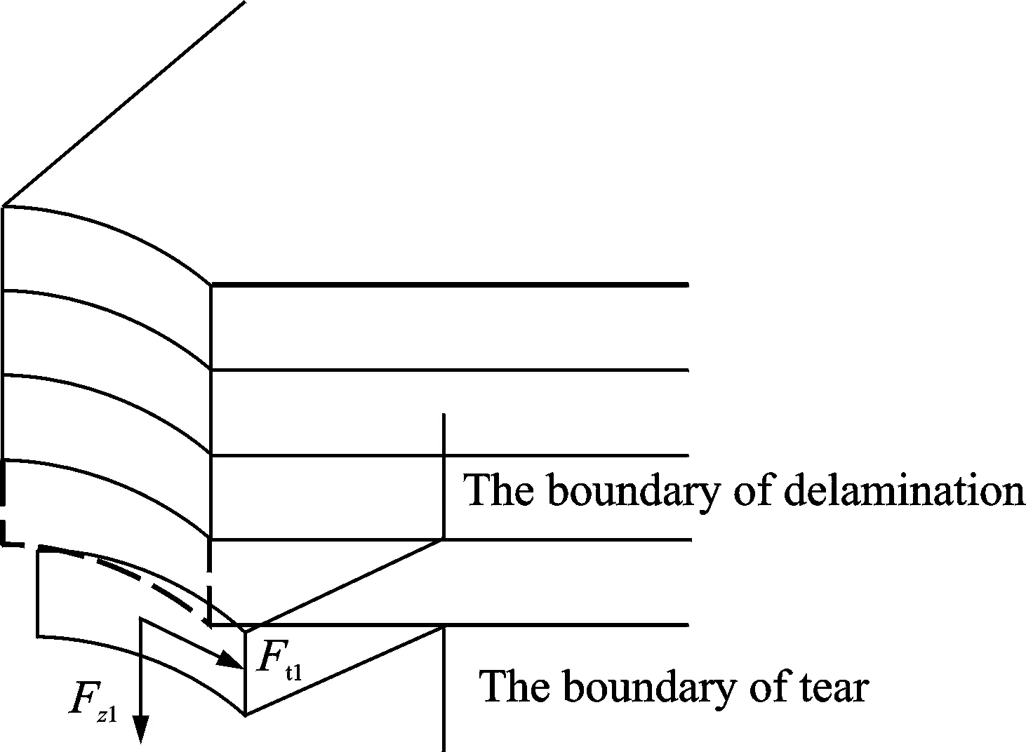
Fig.15 Formation model of exit tear
The exit tear becomes more obvious especially when axial force gets larger. At the moment, the speed of stress variation at the hole edge is much quicker than that at the delamination edge far away from the tool, and the hole bottom materials still keep a certain thickness, which could resist deformation to some extent. Thus, cover type tear is easy to be formed at the hole exit. When axial feed pitch is set at a small value, front cutting edge produces little axial force, which leads to a small scope of exit delamination. At the same time, the stress variation at the hole edge is quickly passed to the edge of delamination, and the uncut materials at the hole bottom are thinning, whose property of resisting deformation is reducing. Thus, open type torn is formed at the hole exit. When a tool cuts through CFRP laminates, side cutting edge is still machining the hole exit till the end of OD.
In general, excessive axial and tangential forces during CPOD of CFRP are the principal causes to form delamination and tear at the hole exit. The axial force comes from front cutting edge, and the tangential force comes from front and side cutting edges. To restrain delamination and tear at the hole exit, optimization of cutting parameters is suggested to reduce axial and tangential forces.
5 Conclusions
(1) The typical defects at the hole entrance and exit are tear and burr during CPOD of CFRP. Meanwhile, tear is more obvious than burr, and more entrance tear emerges often than exit tear.
(2) The contrast test between CPOD and PD of CFRP shows that the former could reduce axial force by about 50%, and bring about bigger tangential and radial force at the same time.
(3) The single factor experiment results show the following conclusions:① the variation of rotation speed has small effect on entrance and exit tear. ② The increase of tangential feed per tooth could worsen entrance tear, but has no effect on exit tear nearly. ③ The increase of axial feed pith could sharply enlarge entrance and exit tear. ④ The increase of revolution radius could firstly eliminate entrance and exit tear, and then enlarge entrance and exit tear.
(4) The formation models of delamination and tear at the hole entrance are established. They show that entrance delamination is mainly caused by upward axial force which is resulted from side cutting edge, and entrance tear is caused by aforesaid upward axial force and tangential force which comes from side cutting edge.
(5) The formation models of delamination and tear at the hole exit are also established. From the models, it can be seen that exit delamination is caused by downward axial force resulted from front cutting edge, and exit tear is caused by downward axial force from front cutting edge and tangential force resulted from side and front cutting edge.
Acknowledgements
This work was supported in part by the Major Project of the Ministry of Science and Technology of China (No.2012ZX04003-031) and the Innovation Project of Jiangsu Province (No.2016-05).
[1] CAO C X. One generation of material technology, one generation of large aircraft[J]. Acta Aeronautica Et Astronautica Sinica, 2008,29(3):701-706.
[2] CHEN M, AN Q L, MING W W. Drilling of composite materials[M]. Beijing: National Defense Industry Press, 2013.
[3] BI S S, LIANG J. Robotic drilling system for titanium structures[J]. Int J Adv Manuf Technol, 2011, 54(5/8): 767-774.
[4] XU J H, MU J, CHEN Y, et al. Analysis on CFRP holemaking with brazed diamond core drill[J]. Journal of Nanjing University of Aeronautics and Astronautics, 2012, 44(5): 747-753.(in Chinese)
[5] DURAO A M, CAMPOS R J C, FARIA P E, et al. The effect of cutting tools geometry on thrust and delamination when drilling glass fiber reinforced plastic composite[J]. Materials and Design,2008, 29(2):508-513.
[6] MU Juan. Fundamental research on drilling carbon fiber reinforced plastics with brazed diamond tool[D]. Nanjing: Nanjing University of Aeronautics and Astronautics, 2013. (in Chinese)
[7] LACHAUD F, PIQUET R, COLLOMBET F. Drilling of composite structures[J]. Composite Structure, 2001, 52(4):511-516.
[8] TSAO C C. Experimental study of drilling composite materials with step-core drill[J]. Materials and Design, 2008, 29: 1740-1744.
[9] TSAO C C, CHIU YC. Evaluation of drilling parameters on thrust force in drilling carbon fiber reinforced plastic(CFRP) composite laminates using compound core-special drills[J]. International Journal of Machine Tools & Manufacture, 2011,51:740-744.
[10]KRISHNARAJM V, PRABUKARTHI A, RAMANTHAN A. Optimization of machining parameters at high speed drilling of carbon fiber reinforced plastic(CFRP) laminates[J]. Composites, 2012,43:1791-1799.
[11]WONM M S, DHARANM C K. Chisel edge an pilot hole effects in drilling composites laminates[J]. Journal of Manufacturing Science and Engineering, 2002, 124: 242-247.
[12]KHASHABAM U A. Delamination in drilling GFR-thermoset composites[J]. Composite Structures. 2004, 63(3/4):313-327.
[13]DHARAN C H, WON M S. Machining parameters for an intelligent machining systems for composite laminates[J]. International Journal of Machine Tools & Manufacture, 2000, 40:415-426.
[14]JAIN S, YANG D C H. Effects of federate and chisel edge on delamination in composites drilling[J]. ASME Journal of engineering industry, 1993,115(4):398-405.
[15]TSAO C C, HOCHENG H. Effects of exit back-up on delamilation in drilling composites materials using a saw drill and a core drill[J]. International Journal of Machine Tools & Manufacture, 2005, 45:1261-1270.
[16]TONSHOFF H K, SPINTIG W. Machining of holes: Developments in drilling technology[J]. Annals of the CIRP, 1994, 43:551-561.
[17]NI Wangyang. Orbital drilling of aerospace materials[C]//SAE Transactions Set. Los Angeles: SAE International, 2008(V116): 2007-01-3814.
[18]WANG B, GAO H, EI M Z, et al. Mechanism of reduction of damage during orbital drilling of C/E composites[J], Chinese Journal of Mechanical Engineering, 2012, 48(15):173-181.
[19]SHAN Y C, HE N, LI L, et al. Predictive modeling and parameter optimization of cutting forces during orbital drilling[J]. Transactions of Nanjing University of Aeronautics and Astronautics, 2014, 31(5): 521-529.
[20]YANG Y F, SHAN Y C, HE N, et al. Theoretical and experimental analysis on influence of revolution radius in orbital drilling [J]. Transactions of Nanjing University of Aeronautics and Astronautics, 2014, 31(5): 498-507.
[21]SHIGEMOTO A, HIROKI I. Effect of cutting revolution on cutting temperature in helical milling of CFRP composite laminates[J]. Key Engineering Materials, 2012, 523/524:58-63.
[22]WANG H Y. Study on dynamics in helical milling of difficult-to-cut materials[D]. Tianjing: Tianjing University, 2013. (in Chinese)
[23]DENKENA B, BOEHNKE D, DEGE J H. Helical milling of CFRP-titanium layer compounds [J]. CIRP Journal of Manufacturing Science and Technology, 2008, 2(1): 64-69.
[24]SHAN Y C. Fundamental research on the helical milling process of holes for aero laminated structure materials [D]. Nanjing: Nanjing University of Aeronautics and Astronautics, 2014. (in Chinese)
[25]SHAN Y C, HE N, LI L, et al. Orbital milling hole of aerospace al-alloy with big pitch[J]. Transactions of Tianjin University, 2011, 17(5): 329-335.
Mr.Shan Yicai, born in 1976, is currently a Ph.D. candidate in college of Mechanical & Electrical Engineering, Nanjing University of Aeronautics and Astronautics, China. He is an associate professor in Nanjing College of Information Technology, China. His research interests include robotic hole-making technology and advanced cutting process.
Prof.He Ning, born in 1959, is currently a professor in Nanjing University of Aeronautics and Astronautics, China. His research interests include high speed cutting and hard machining materials processing technology, processing and deformation analysis and control, micro cutting technology.
Prof.Li Liang, born in 1973, is currently a professor in Nanjing University of Aeronautics and Astronautics, China. His research interests include high speed cutting and hard machining materials processing technology, micro cutting technology.
Ms.Zhang Ting, born in 1979, is currently a Ph.D. candidate in college of Mechanical & Electrical Engineering, Nanjing University of Aeronautics and Astronautics, China. She is a lecturer in Nanjing Institute of Technology, China. Her research interests include machine tool accuracy control and error compensation.
(Executive Editor: Zhang Bei)
TG.146.23 Document code:A Article ID:1005-1120(2016)06-0696-10
*Corresponding author,E-mail address: nj_syc@163.com. How to cite this article: Shan Yicai, He Ning, Li Liang, et al.Entrance and exit defects during coarse pitch orbital drilling of carbon fiber reinforced plastic plates[J]. Trans. Nanjing Univ. Aero. Astro., 2016,33(6):696-705. http://dx.doi.org/10.16356/j.1005-1120.2016.06.696
杂志排行
Transactions of Nanjing University of Aeronautics and Astronautics的其它文章
- Capacity Analysis on Distributed Antenna System with Imperfect CSI over Rayleigh Fading Channel
- Construction of Low Delay Maximal Rate Single-Symbol Decodable Distributed STBC with Channel Phase Information
- A Directional Differential-Fed UWB Antenna with Stable Radiation Pattern
- Numerical Simulation of An Axial Flow Fan with Proper Aft Fins for Floating Wind Turbines Model Test
- Acknowledgement to Reviewers
- TRANSACTIONS OF NANJ ING UNIVERSITY OF AERONAUTICS AND ASTRONAUTICS
