A Directional Differential-Fed UWB Antenna with Stable Radiation Pattern
2016-02-09,,,,
, , , ,
1.School of Electronics and Information, Northwestern Polytechnical University, Xi′an 710072, P.R. China;2.Science and Technology on UAV Laboratory, Northwestern Polytechnical University, Xi′an 710065, P.R. China;3.School of Computer Science and Technology, Xidian University, Xi′an 710071, P.R. China
A Directional Differential-Fed UWB Antenna with Stable Radiation Pattern
FangYang1,WangBaoping2*,SunChao1,SongZuxun1,WangShuzhen3
1.School of Electronics and Information, Northwestern Polytechnical University, Xi′an 710072, P.R. China;2.Science and Technology on UAV Laboratory, Northwestern Polytechnical University, Xi′an 710065, P.R. China;3.School of Computer Science and Technology, Xidian University, Xi′an 710071, P.R. China
(Received 7 December 2015; revised 26 July 2016; accepted 29 August 2016)
A directional ultra-wideband (UWB) antenna with improved radiation patterns is presented. The proposed sheme comprises a differential-fed microstrip antenna and a rectangular cavity. The hexagon-shaped slot and four triangle-cut corners on the ground plane of the planar antenna are used to improve the impedance matching within the UWB frequency range. A rectangular cavity is used as the reflector for the planar microstrip antenna, so as to achieve directed radiation. The measured results indicate that the designed antenna exhibits a stable broadside directional radiation patterns within the entire operating frequency band. Furthermore, thanks to the differentially driven technique, the cross-polarization is greatly decreased and the polarization purity is maintained in a high level.
differential-fed; ultra wide band; microstrip antenna
0 Introduction
Thanks to the advantages of high date rate, great capacity, simplicity, and low cost, ultra-wideband (UWB) short-range wireless technology has attracted more and more attention since the Federal Commercial Commission (FCC) released the frequency band 3.1—10.6 GHz for commercial UWB systems[1]. As an important component of UWB system, UWB antenna holds appealing features of simple structure, wide impedance bandwidth (BW), stable radiation patterns, and constant gain in the desired direction. So far, various planar UWB antennas have been presented[2-6]. However, those planar antennas exhibit omnidirectional radiation patterns. In some applications that require unidirectional radiation patterns, the planar antennas will waste radiation power in needless directions. Thus, UWB antennas with stable directional radiation patterns are needed. Although some directed UWB antennas have been proposed[7-9], most of them have a common deficiency: Radiation pattern degrading in high frequency band. Most degradations mean splitting the radiation pattern, low polarization purity of the radiation pattern in the high frequency band, etc.
Recently, the differential-fed antennas have been increasingly popular, thanks to their easy integration with the differential devices, low cross polarization and so on[10-16]. A differential-fed directional UWB antenna with improved radiation patterns is presented. The proposed antenna comprises a differentially driven microstrip antenna and a rectangular cavity. The rectangular cavity, working as a reflector, unidirectional reflect radiation within the entire operation frequency band. Furthermore, thanks to the differentially excited strategy, the cross-polarization level is maintained less 20 dB than co-polarization over the whole UWB frequency range, which results in high polarization purity of radiation patterns. All the simulated results are drawn by using the software of ANSYS high frequency structure simulator (HFSS), a commercial 3-D full-wave electromagnetic simulation tool.
1 Antenna Configuration
Fig.1 shows the configuration of the differential-fed planar antenna backed by a rectangular cavity. The proposed differentially driven microstrip antenna is printed on FR4 substrate with thickness of 1 mm, relative dielectric constant of 4.4, and loss tangent of 0.02. As shown in Fig.1(b), on top of the substrate, the differential microstirp feeding lines are etched, loading with two partially cut elliptical patches. The width of the feeding lines is chosen as 1.86 mm to achieve the characteristic impedance of 50 Ω. For good impedance matching, part of the feeding lines taper from 1.86 mm to 1 mm. The ground plane with central hexagon-shaped slot is printed on the bottom side of the substrate. Four corners of the ground plane are cut to further ameliorate the impedance matching, especially in the high frequency band. To realize the stable wideband directional radiation patterns, the proposed planar antenna is backed by an inverted pyramidal cavity with a inverted pyramidal cross section which occupies a volume of 70 mm×85 mm×10 mm. Two coaxial cables are used to conveniently feed the differenti-al antenna. The coaxial inner conductor is con-nected to the feedline of top planar patch, while the outer conductor is connected both the ground of the top patch antenna and the backed cavity. Based on the optimized parameters on Table 1, an antenna prototype is designed and fabricated as shown in Fig.1(c).
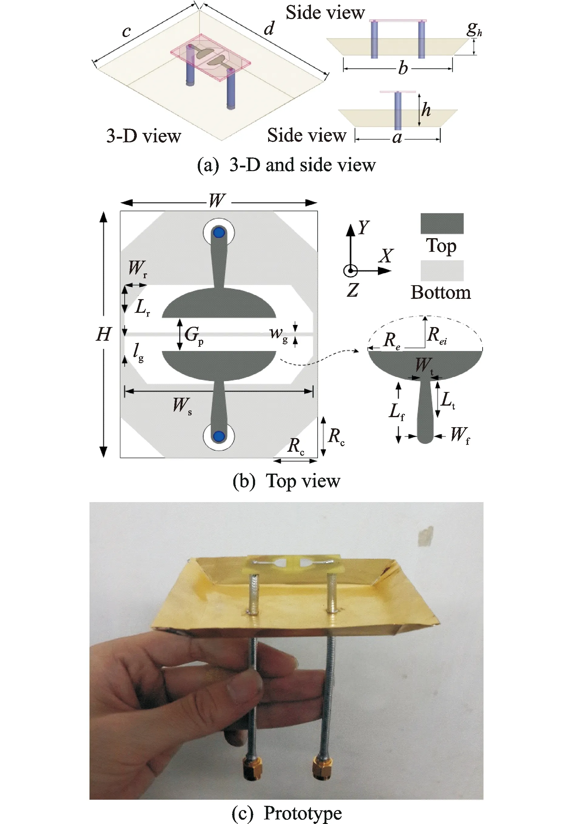
Fig.1 Configuration of the proposed antenna
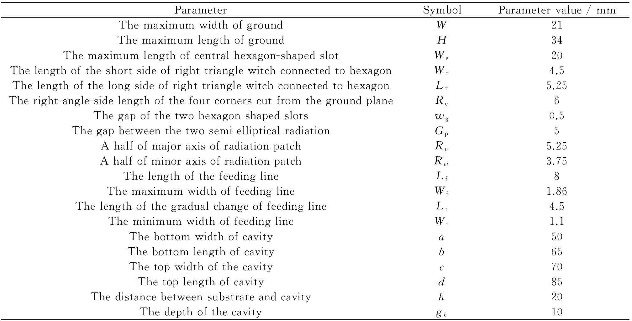
Table 1 Optimized antenna parameters
2 Antenna Design and Analysis
2.1 Differential-fed microstrip antenna
A differential-fed antenna can be regarded as a two-port differential device, excited by two signals with equal amplitude and out of phase. Thus the reflection coefficient of the differentially driven can be defined as
(1)
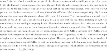
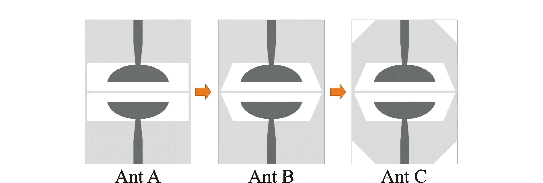
Fig.2 The evolving process of the top planar patch
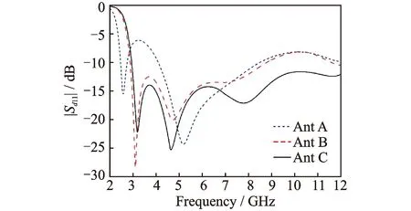
Fig.3 The simulated |Sd11| results of Ants A, B, and C
2.2 Proposed directional UWB antenna
Fig.4 shows the simulated three-dimensional radiation plots of the planar differential-fed antenna without backed cavity. It can be observed that the main beams of the antenna are stabilized in the broadside direction within the whole frequency range. This stable radiation property may somewhat avoid splitting radiation pattern, especially in the high frequency band, when the proposed antenna is backed with a reflector. Here, instead of a planar reflector, an inverted pyramidal cavity, which is placed 21 mm away from the ground plane of the microstrip antenna, is used to realize the directional radiation patterns. Fig.5 shows the comparison of gains in the broadside direction for the antenna backed by a planar reflector and the proposed cavity with a same horizontal area. It can be seen that by using the inverted pyramidal cavity as the reflector, the realized gain of the antenna, especially in the high frequency band, can be increased to some extent. Fig. 6 shows the simulated |Sd11| results of the differential-fed antenna with and without the cavity in their optimized parameters, which indicates that the impedance matching would degraded both in the low and high frequency bands for introducing the cavity.

Fig.4 The simulated 3-D radiation plots of the top planar antenna
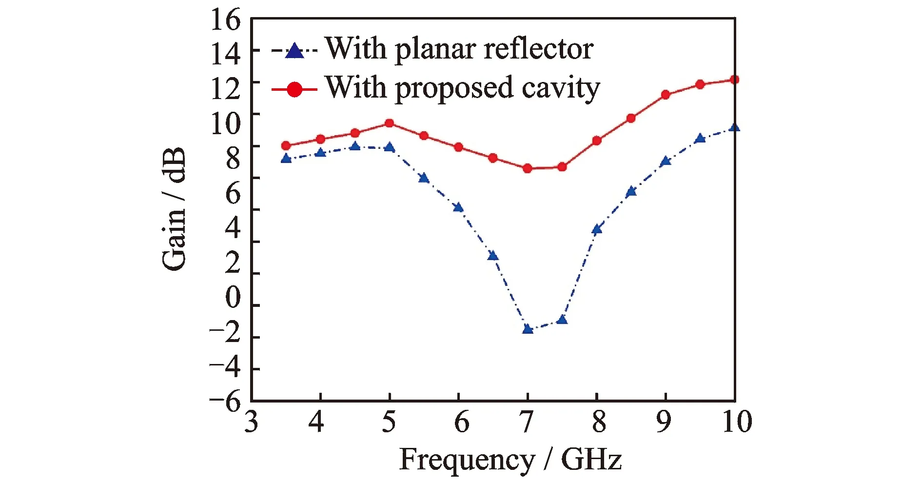
Fig.5 The gain comparison for the antenna backed by a planar reflector and the proposed cavity
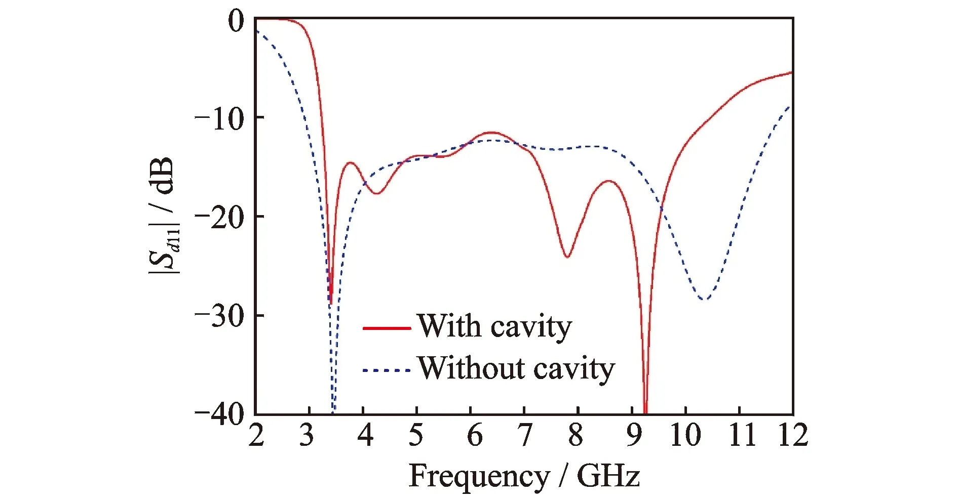
Fig.6 The simulated |Sd11| results of the antenna with and without the cavity
2.3 Measured result and discussion
An Agilent N5230A vector network analyzer is used to measure theS-parameter:S11,S22,S12, andS21for the proposed antenna. Then the differential reflection coefficient |Sd11| can be obtained by using Eq.(1). Fig.7 shows the measured and simulated results of the designed directional differential-fed UWB antenna. It can be seen that the fabricated antenna can achieve an UWB performance from 3.3 to 10.4 GHz for |Sd11|<-10 dB. The discrepancy between the simulated and the measured results is probably owing to the fluctuation constant or process tolerance.
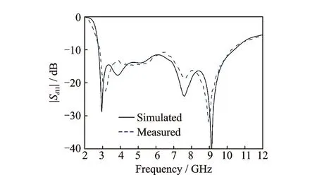
Fig.7 The measured and the simulated results of the proposed antenna
In the radiation pattern measurement, be-cause the differential excited signals are hard to be implemented directly, a UWB anti-phase power hybrid coupler Krytar 4020180 is used to measure the radiation characteristics of the proposed differentially driven antenna. The radiation patterns in the E- and H-plane at 3.5, 6, 8, and 10 GHz are plotted in Fig.8, where Sim-Co represents the simulation result of main polarization of radiation pattern; Sim-Cx the simulation result of cross-polarization of radiation pattern; Mea-Co the measurement result of main polarization of radiation pattern; Mea-Cx the measurement result of cross-polarization of radiation pattern. It can be seen that the proposed antenna exhibits a stable directional radiation patterns within the entire operating frequency band. Moreover, all the measured cross-polarization levels of the designed antenna are less -20 dB than the cross-polarization, which means that the polarization purity can be maintained in a high level across the whole UWB frequency range. Fig.9 shows the simulated and the measured gains of the antenna in the broadside direction. It should be noted that the measured gains have been amended by removing the transmission loss of the power hybrid coupler. From 3.5 to 10.5 GHz, the measured gain is confined between 7 and 11 dB, while the simulated gain varied in the range of 7.3—12.5 dB. Since the 180° power hybrid coupler may not be perfect, there exists a disagreement between the simulated and the measured results.
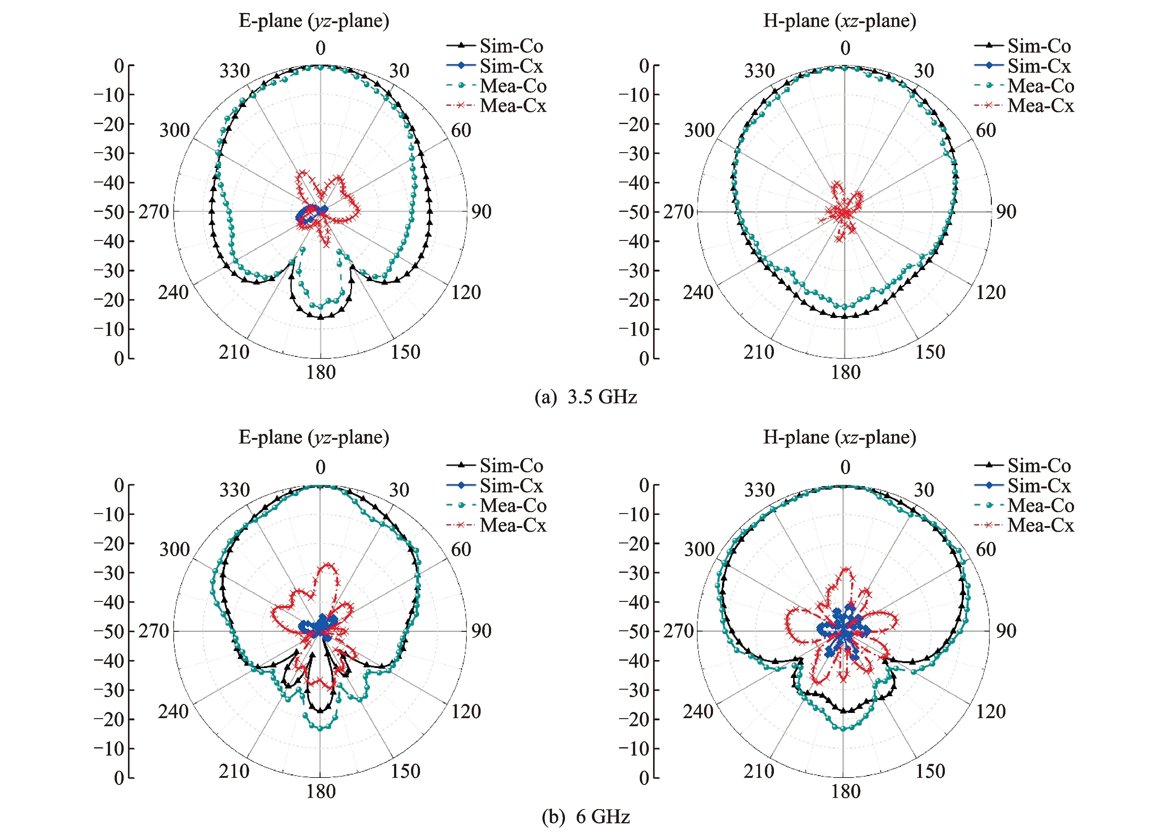
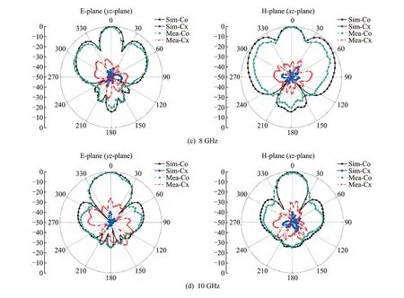
Fig.8 The radiation patterns in the E- and H-planes at different frequencies
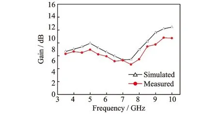
Fig.9 The simulated and the measured gains of the proposed antenna in the broadside direction
3 Conclusions
In this study, a directional differential-fed antenna is presented for some UWB communication systems. Thanks to the hexagon-shaped slot in the central part of the ground plane, the impedance matching of the antenna is greatly improved, especially in the low frequency band. To further improve the impedance matching at high frequencies, four symmetrical isosceles right triangles are cut from the four corners of the ground plane. An inverted pyramidal cavity is used as the reflector for the planar antenna so that the stable directional radiation patterns is obtained. More importantly, thanks to the differentially driven strategy, the cross-polarization is kept in a low level within the whole operating frequency range, which results in high polarization purity of the antenna. Therefore, the simple structure and improved radiation patterns lead the proposed antenna to a broader future of various UWB utilizations.
Acknowledgements
This work was supported in part by the National Natural Science Foundation of China (Nos.61472324, 61073106, 61540028).
[1] Federal Communications Commission (FCC). ET-Docket FCC02-48, Revision of part 15 of the commission′s rules regarding ultra-wideband transmission systems FCC [S]. Washington, D.C.:[s.n.], 2002.
[2] LIANG J X, CHIAU C C, CHEN X D, et al. Study of a printed circular disc monopole antenna for UWB systems[J]. IEEE Transactions on Antennas and Propagation, 2005, 53(11): 3500-3504.
[3] LIN Y C, HUNG K J. Compact ultrawideband rectangular aperture antenna and band-notched designs[J]. IEEE Transactions on Antennas and Propagation, 2006, 54(11):3075-3081.
[4] SIM C, CHUNG W T, LEE C H. Compact slot antenna for UWB applications[J]. IEEE Antennas and Wireless Propagation Letters, 2010, 9: 63-66.
[5] LI D T, MAO J F. A Koch-like sided fractal Bow-Tie dipole antenna: Antennas and propagation[J]. IEEE Transactions on Antennas and Propagation, 2012, 60(5): 2242-2251.
[6] HUANG X D, CHENG C H, ZHU L. An ultrawideband (UWB) slotline antenna under multiple-mode resonance[J]. IEEE Transactions on Antennas and Propagation, 2012, 60(1): 385-389.
[7] MOODY R A, SHARMA S K. Ultrawide bandwidth (UWB) planar monopole antenna backed by novel pyramidal-shaped cavity providing directional radiation patterns[J]. IEEE Antennas and Wireless Propagation Letters, 2011, 10: 1469-1472.
[8] ELSHERBINI A, SARABANDI K. Directive coupled sectorial loops antenna for ultrawideband applications[J]. IEEE Antennas and Wireless Propagation Letters, 2009, 8: 576-579.
[9] NAIR S M, SHAMEENA V A, DINESH R, et al. Compact semicircular directive dipole antenna for UWB applications[J]. Electronics Letters, 2011, 47(23): 1260-1262.
[10]MA C Y, LI Z G. Beamforming of whole airspace phased array TT & C system based on linear subarrays[J]. Transactions of Nanjing University of Aeronautics and Astronautics, 2015, 32(1): 128-132.
[11]HUM S V, HUI Y X. Analysis and design of a differentially-fed frequency agile microstrip patch antenna[J]. IEEE Transactions on Antennas and Propagation, 2010, 58 (10):3122-3130.
[12]ZHANG Y P. Design and experiment on differentially-driven microstrip antennas[J]. IEEE Transactions on Antennas and Propagation, 2007, 55 (10):2701-2708.
[13]XUE Q, ZHANG X L, CHIN C H K. A novel differential-fed patch antenna[J]. IEEE Antennas and Wireless Propagation Letters, 2006, 5(1): 471-474.
[14]WU H W, ZHANG J, YAN L Y, et al. Differential dual-band antenna-in-package with T-shaped slots[J]. IEEE Antennas and Wireless Propagation Letters, 2012, 11:1446-1449.
[15]SIM C, CHANG C C, ROW J S. Dual-feed dual-polarized patch antenna with low cross polarization and high isolation[J]. IEEE Transactions on Antennas and Propagation, 2009, 57(10): 3321-3324.
[16]JIN K, ZHAN D W, YANG Y, et al. Design of compact and high gain differential micro-strip antenna[J]. Journal of Nanjing University of Aeronautics and Astronautics, 2015, 49(6): 911-916. (in Chinese)
Mr. Fang Yang received his M.S. degree from School of Electronics and Information, Northwestern Poly technical University. He is currently a Ph.D. candidate working in department of Electronics and Information, Northwestern Polytechnical University. His current research interests include telemetry antenna, radar imaging and imaging processing.
Prof. Wang Baoping received his Ph.D. degree from Department of Electronic Engineering, Xidian University, in 2004. He is now a professor and a master instructor in National Key Laboratory of Science and Technology on UAV. So far he has published more than 30 papers, in which two papers were indexed by SCI and ten papers by EI. His current research interests include imaging processing, radar imaging.
Mr. Sun Chao received his B.S. degree in electronic information science and technology from Qufu Normal University, in 2010, and M.S. degree in signal and information processing from Northwestern Polytechnical University, in 2013, where he is currently working as a Ph.D. candidate in information and communication engineering. His research interest is radar imaging.
Prof. Song Zuxun received his Bachelor, Master, and Ph. D. degrees in School of Electronics and Information, Northwestern Polytechnical University in 1986, 1989, and 2004, respectively. He now is a professor in the School of Electronics and Information, Northwestern Polytechnical University. His research interests include signal information acquisition and processing, overall design of microwave communication link, and EMC design and diagnosis.
Prof. Wang Shuzhen is currently an associate professor in the School of Computer Science and Technology, Xidian University. He received his Ph.D. degree from School of Electro-Mechanical Engineering, Xidian University in 2005. So far he has published more than 20 papers, in which four papers were indexed by SCI. His research interests include radar imaging, machine learning, and computer vision.
(Executive Editor: Zhang Bei)
TN823 Document code:A Article ID:1005-1120(2016)06-0747-07
*Corresponding author, E-mail address: wbpluo@sina.com. How to cite this article: Fang Yang, Wang Baoping, Sun Chao, et al. A directional differential-fed UWB antenna with stable radiation pattern[J]. Trans. Nanjing Univ. Aero. Astro., 2016,33(6):747-753. http://dx.doi.org/10.16356/j.1005-1120.2016.06.747
杂志排行
Transactions of Nanjing University of Aeronautics and Astronautics的其它文章
- A Sequential Adaptive Method for Enhancing DOA Tracking Performance
- Construction of Low Delay Maximal Rate Single-Symbol Decodable Distributed STBC with Channel Phase Information
- Numerical Simulation of An Axial Flow Fan with Proper Aft Fins for Floating Wind Turbines Model Test
- Capacity Analysis on Distributed Antenna System with Imperfect CSI over Rayleigh Fading Channel
- Acknowledgement to Reviewers
- TRANSACTIONS OF NANJ ING UNIVERSITY OF AERONAUTICS AND ASTRONAUTICS
