Distribution features of cuttings bed and sensitivity analysis of major drilling parameters for cuttings transport in gas drilling horizontal wells*
2015-12-01祝效华,易静,刘清友
Distribution features of cuttings bed and sensitivity analysis of major drilling parameters for cuttings transport in gas drilling horizontal wells*
ZHU Xiao-hua (祝效华), YI Jing (易静), LIU Qing-you (刘清友)
School of Mechatronic Engineering, Southwest Petroleum University, Chengdu 610500, China,
E-mail:Zxhth113@163.com
(Received March 7, 2014, Revised August 19, 2014)
In the current engineering methods for the gas horizontal drilling, the distribution features of cuttings bed remain an issue to be cleared, and the gas horizontal drilling is still in early stages of development. For on-site drilling, a 3-D transient model is established in this paper to simulate the distribution features and the transport mechanism of the cuttings bed, based on the gas-solid two-phase flow theory. The effects of major drilling parameters, such as the gas velocity, the drill pipe rotation, the cutting size and the eccentricity, on the cuttings transport efficiency are analyzed. The major findings of this study include that the cuttings begin to settle down and build up a fixed cuttings bed, in the most evident regions in front and behind the connector, the dominant parameter of the wellbore cleaning is the gas velocity, and, as the cutting size is increased, the thickness of the cuttings bed developed in the wellbore increases significantly. In addition, the eccentricity has some influence on the cuttings transport, and the drill pipe rotation has little effect on the cuttings transport.
gas drilling, horizontal well, cuttings transport, sensitivity analysis
Introduction0F
The technology of the gas horizontal drilling has made a great contribution to increasing the penetration rate in hard formations and increasing their productivity, as well as expanding the seepage area, protecting the reservoir and reducing the drilling costs[1-4]. However, in the gas horizontal drilling, the cuttings settle down in the lower wall due to gravity, and as a result build up a fixed cuttings bed. Many severe problems are caused by the cuttings bed deposited on the lower wall, such as the high torque and drag, the stuck pipe,and the back pressure. Therefore, the wellbore cleaning is one of the key technologies in the gas horizontal drilling, and the central issue is to control the effects of these parameters on the cuttings transport. In 2000, the statistics from the Anhui Oil Exploration and Development Company show that the pipe stuck accidents in horizontal wells account for 3.43%-11.67% of the total completion time, and an economical loss of millions of dollars or more is caused due to the poor wellbore cleaning[5-7].
Since the 1950s, various mathematical models were developed to predict the performance of the gas drilling operations. The earliest theory of the dry gas drilling operations was proposed by Martin, but he did not consider the cuttings effects in the flow and also the temperature variation with depth. Based on Martin's method, Angel developed the first mathematical model to be applied for the gas drilling operations and derived the formula for the minimum volume requirements, but the investigation was focused mostly on problems in vertical wells. As interest was turned to directional and horizontal wells, studies were shifted to experimental approaches. Richard analyzed the special problems in the air horizontal drilling and verified the importance of the non-uniformity of the cutting size in determining the air velocity by means of experiments. Based on the Fanning friction coefficient model, Guo and Lee improved the formula proposed by Angel, and applied it to the short horizo-ntal section of horizontal wells. However, there are not many studies for the gas-solid behavior in the annulus and different controllable variables, to optimize the cuttings transport performance in the air horizontal drilling.
Currently, the gas horizontal drilling is still in a preliminary stages of development. Many issues, such as the cuttings transport, the wellbore stability, and the MWD, remain to be resolved for the gas horizontal drilling, especially in long horizontal sections. Almost no theoretical studies are focused on the distribution features of the cuttings bed in the gas horizontal drilling, as are essential in the implementation of gas horizontal drilling operations. Based on the gas-solid two phase flow theory, this paper uses a simulation model of the cuttings transport in the gas horizontal drilling, to investigate the effects of the gas velocity,the cutting size, the drill pipe eccentricity and the drill pipe rotation on the cuttings transport. In this study,the commercial CFD packages including Gambit2.2.30 and Fluent6.2.16 are used to build the physical models, then the governing equations are solved with the finite volume method.

Fig.1 Cuttings transport patterns in horizontal wellbore
1. Analysis model
1.1 Cuttings transport patterns
In a horizontal wellbore, the annulus velocity component in the vertical direction is almost zero. Therefore, due to gravity and without the corresponding speed lifting the cuttings upward, the cuttings begin to settle down and to build up a fixed cuttings bed, which is difficult to be cleaned. As shown in Fig.1(a)[8,9], due to the fact that the drill pipes are in the wellbore as an eccentric annulus in the horizontal section, the cuttings bed will become hierarchical. At this moment a layer of stationary cuttings bed, known as the fixed cuttings bed, will appear close to the lower wall. Due to the dispersion of the cuttings particles, a part of the solid particles, especially the smaller cuttings, are dispersed to the upper air flow, forming a suspension stream layer. The moving cuttings bed between the suspended layer and the fixed layer can slide as a whole. Figure 1(b) shows three cuttings transport patterns in an eccentric wellbore of the horizontal well: the suspension type, the moving bed type,and the fixed bed type. When the cuttings transport stably in the eccentric annulus, those between the layers are in a relative dynamic balance.
1.2 Computational model
1.2.1 Two-phase flow model
In the case of dry gas and when a small amount of formation water is present in the gas horizontal drilling, the flow in the annulus wellbore can be seen as a gas-solid two-phase flow. Presently, the Euler-Lagrange and Euler-Euler methods are used to study the multiphase flow. The Euler-Lagrange method is mainly used for the sparse two-phase flow, but the Euler-Euler method can be used without a limit of the volume fraction of each phase. The medium of different phases is taken as a continuous one with the momentum, the mass and the energy exchanges between the dispersion phase and the fluid phase. As the cuttings transport is a type of pneumatic transport and this paper's main concern is the cuttings settlement, and the Euler multiphase flow model in the Euler-Euler method is selected.
The RNG k-εmodel is used for the numerical calculations in this paper due to the considerations as follows.
The commercial code Fluent 6.2.16 mainly provides the following choices of k-εturbulence models[10]: the standard k-εmodel, the RNG k-ε model, and the realizable k-εmodel. The standard k-εmodel, proposed by Wilcox (1998), is the best choice for the isotropic turbulent motion, as it has no rotational flow or complex flow associated with secondary flows, and enjoys high stability, efficiency and computational accuracy. The realizable k-εmodel, proposed by Shih et al. (1995), is mostly used in the simulation of a shear flow or free flow. The RNG k-εmodel, which is derived by using a rigorous statistical technique and proposed by Yakhot and Orzag(1986), is commonly used to deal with a distorted or rotational flow, and is advantageous in dealing with high strain rate fluid flows.
In view of the research objectives in this paper and the fact that the returned gas with cuttings in the horizontal well is highly irregular high-Reynoldsnumber turbulence flow, the RNG k-εmodel should be the most appropriate method to solve the gas-solid two-phase flow in this study.
1.2.2 Assumptions
(1) Air is simulated as incompressible gas.
(2) Particles are simulated as incompressible balls with uniform size.
(3) The mass transfer, the boundary layer effect of wall and the heat transfer of wall are neglected, to simplify the computation.
Based on the above assumptions, the governing equations, which include those of continuity, momentum, turbulent kinetic energy(k ), and turbulence dissipation rate(ε), are expressed as follows[11-17].
1.2.3 Continuity and momentum equation

where ag,ρgand vgrespectively represent the volume fraction, the density and the gas velocity.τg, fdrag,g,Vpi,ΔV,Fdragand nrepresent the gas shear stress, the volumetric gas-particle interaction force, the gravitational acceleration, the volume of particlesi inside the cell, the volume of a computational cell, the gas drag force on an individual particle, and the number of particles in the cell.
1.2.4k-εequations of RNG k-εmodel
The RNG k-εmodel is as follows:
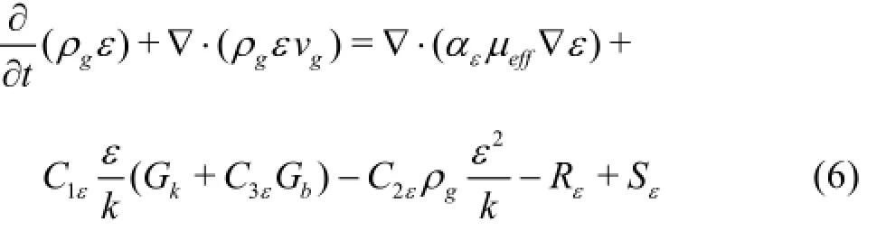
where µeff,kandεrepresent the equivalent viscosity of gas, the turbulent kinetic energy and the turbulence dissipation rate, respectively.Gk,Gband YMrepresent the generation of the turbulence kinetic energy due to the mean velocity gradients, the generation of the turbulence kinetic energy due to the buoyancy,and the contribution of the fluctuating dilatation of the compressible turbulence in the overall dissipation rate, respectively.Skand Sεare the user-defined source terms, and αkand αεare the inverse effective Prandt1 numbers forkandε, respectively.C1ε= 1.42,C2ε=1.68and C3ε=1.3.

Fig.2 Range of the cutting diameter according to the field data
1.2.5 Simulation conditions
In this study, the gas-phase is air, and the discrete-phase is the particles of the cuttings. The numerical computations for the 3 000 m deep well are conducted under the eccentricity(e)of 0.2, the operating pressure (Pannular)of 1.2 MPa, the annulus diameter (Dw) of 0.1524 m, the drill pipe diameter (Dd)of 0.0889 m, and the drill pipe rotation(R)of 30 r/min. The rate of penetration (ROP) is 30 m/h, which is calculated according to the inlet volume fraction of cuttings(Voverall)of 0.003, and the gas injection rate(Q)is 90 m3/h-150 m3/h, which is calculated according to the gas velocity (vg)of 12 m/s-20 m/s. According to the field data, the cutting size(D)is about 0.45× 10⁻³m-5.93×10⁻³m (as shown in Fig.2). The input values for the CFD models are vs=12 m/s-20 m/s, vg=12 m/s-20 m/s,Dd=0.0889 m,Dw= 0.1524 m,R =30r/min,e =0.2,ρg=16.38 kg/m3,ρ=2 600 kg/m3,V=0.003,P=1.2 MPa,s


Fig.3 Schematic diagram of the calculation model of the drilling pipe
overallannularD=0.45× 10⁻³m-5.93× 10⁻³m and well depth= 3 000 m.
1.3 Physical models and boundary conditions
1.3.1 Physical models
As the drill pipe in the wellbore changes randomly, this paper makes the following assumptions: (1)The cross-section of the borehole is circular, without considering the irregular borehole. (2) The drill pipe in the wellbore is either centered or eccentric, and other more complex situations are not considered.
As shown in Figs.3(a)-3(c), the physical model is developed.o,o′ande′represent the center of the wellbore section, the center of the drill pipe section, and the distance betweenoando′, respectively. The drill pipe is centered when e′=0, and the drill pipe is eccentric when e′=6.35× 10⁻³m.erepresents the eccentricity and e=2e′/(Dw-Dd). In this study, a part of the drill pipe is considered (the numerical simulations are carried out for two API drilling pipes,each 9 m in length). Whether the drill pipe is centered or eccentric, the flow characteristics of the gas vary with the section of the annulus, particularly at the drill pipe connectors, which may affect the annulus gas flow. Therefore, the drill pipe connectors (API standard) are considered in this paper.

Fig.4 Grids used for the numerical simulation model
1.3.2 Grids
In the gas drilling operations, the gas flow near the wall changes greatly. As shown in Fig.4, in order to study the air flow conditions more accurately, the local grids near the wall are refined, and the structured grids are used.
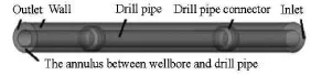
Fig.5 Boundary conditions of numerical simulation model
1.3.3 Boundary conditions
Based on the on-site operations of the gas horizontal drilling, the boundary conditions of the numerical simulation model are shown in Fig.5 and set as follows:
(1) Inlet conditions: The speed of the entrance is set.
(2) Exit conditions: The pressure boundary is consistent with the environmental pressure.
(3) Wall conditions: The wall and the drill pipes are set as the fixed wall and the rotating wall, respectively. The velocity slip is neglected to simplify the computation. The turbulent wall conditions are employed to determine the wall function boundary conditions.

Fig.6 Comparison of the finite element computation with experimental results
2. Verification of the model
In order to verify the accuracy of the calculation model, the two-phase annulus flow under the experimental conditions described in Ref.[18] is considered. The comparison between the finite element calculation result and the experimental result of the annulus pressure at several distances from the inlet is shown in Fig.6, and a good agreement is seen. Therefore, the accuracy of this 3-D simulation model is verified.

Fig.7 Average volume fraction and minimum velocity of cuttings

Fig.8 3-D-visualization of volume distribution nephogram of cuttings in small annulus
3. Results
3.1 Verification of forming cuttings bed in the eccentric annulus of the horizontal section
For the 3 000 m horizontal well, the gas injection rate is about 90 m3/min -150 m3/min. In order to quantitatively study the distributions of the cuttings bed in the eccentric annulus of the horizontal section, and determine whether the fixed cuttings bed will be built up after the particles have settled down, numerical simulations are carried out for the gas injection rate of 150 m3/min and the cutting diameter of 0.001 m. The gas injection rate of 150 m3/min corresponds to the gas velocity of 20 m/s.
(1) As shown in Fig.7, the average volume fraction of the cuttings (vofa)and the minimum velocity of the cuttings (vmin)in the annulus section are used to determine whether or not the fixed cuttings bed would form. At the two drill pipe connectors, the vofais greater than 0.003 and vminis 0 m/s, which indicates that a fixed cuttings bed is built up at the connector. At the drill pipe body, the cuttings with vofaof about 0.004-0.005 begin to settle down, creep at the low speed of 5 m/s-8 m/s at the lower wall, and do not form a fixed cuttings bed. Because vofain front of the drill pipe connectors is less than 0.003, the cuttings do not settle down and move in suspension in the annulus.

Fig.9x-direction volume distribution and axial velocity slice of cuttings near connectors
(2) As shown in Figs.8(a), 8(b) and 9(a), the cuttings settle down in a large extentsand the volume fraction of the cuttings(vof )uprushes in the small annulus of the drill pipe connectors. The maximum volume fraction of the cuttings of about 0.031-0.056 is reached at the drill pipe connectors. As the volume fraction of the cuttings in the large annulus is less than 0.003, the cuttings do not settle down, but move in suspension in the annulus. As shown in Fig.9(b), the velocity of cuttings in the small annulus gradually decreases, and even reaches 0 m/s at a part of the pipe body, which indicates that the stationary cuttings bedis built up there. The annulus cross-sectional area decreases due to the accumulation of cuttings at the lower wall, which increases the velocity of the suspension-layer cuttings in the large annulus slightly, in particular, the axial velocity of the cuttings (vx)at the back surface of the drill pipe connectors reaches about 25 m/s-30 m/s.
Therefore, the cuttings at the connectors of the on-site drilling transport with the three-layer unsteady model are found in the suspension layer, the moving bed layer and the fixed bed layer, i.e. the cuttings settle into the bed.

Fig.10x-direction volume distribution slice of cuttings near connectors at different moments
In order to simulate the process of cuttings settling into the bed in the field, a part of the first drill pipe connector is considered, and the x-direction volume distribution slice of the cuttings near connectors at different moments is calculated. As shown in Figs.10(a)-10(d), in the beginning the cuttings move in suspension with the gas flow, and have a tendency to settle down, especially at the drill pipe connector. The volume fraction of the suspension-layer cuttings in the large annulus decreases significantly over time,and the volume fraction of the cuttings at the lower wall increases significantly.
3.2 Sensitivity analysis for major drilling parameters
In order to study the main parameters that affect the cuttings transport, based on the working parameters in the field, numerical calculations are carried out for different calculation parameters.
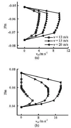
Fig.11 Axial velocity distribution of cuttings along the radial line AB at X=0 m
3.2.1 Gas velocity
It is observed that the most effective drilling parameter for the cuttings bed development is the annular gas velocity. As shown in Figs.11(a)-11(b), the gas velocity has a significant effect on the axial velocity of the cuttings in the small annulus (vxs)and in the large annulus (vx1). The axial velocity of cuttings, which decreases from the center to the outer wall of the drill pipe until reaching zero at the wall, reaches the maximum value in the central region of the annulus. This indicates that the axial velocity of the cutti-ngs in the wall surface is significantly lower than that in the center of the annulus, due to the wall viscous effect. The axial peak velocity of the cuttings in the large annulus increases by 6 m/s following the annular gas velocity. The peak axial velocity of the cuttings in the large annulus at the gas velocity of 20 m/s reaches 18.58 m/s, which is 3.6 times of that at the gas velocity of 12 m/s. As the annular gas velocity is increased,the axial peak velocity of the cuttings in the small annulus increases exponentially by 2 m/s. The peak axial velocity of the cuttings in the small annulus at the gas velocity of 20 m/s reaches 9.58 m/s, which is 2.4 times of that at the gas velocity of 12 m/s. The axial velocity of the cuttings reaches 0 m/s from the borehole to the center of the large annulus, and the axial velocity of the cuttings reaches the maximum value not at the center of the large annulus, but at an offset position. This indicates that only a small amount of cuttings in the large annulus move in suspension with the gas flow, and the cuttings begin to settle down at the outer wall of the drill pipe and move in saltation at a low speed of 1.4 m/s-5.2 m/s. The cuttings of the small annulus settle down in a large extent, and move in the saltation at a low speed of 1.91 m/s-4.06 m/s. As shown in Fig.12, the gas velocity has almost no effect on the tangential velocity of the cuttings in the large annulus (vτl)if the rotation speed of the drill pipe is kept constant. Therefore, under the premise of ensuring the safety of drilling, it is recommended to provide sufficient gas, which is conducive to the cuttings transport.
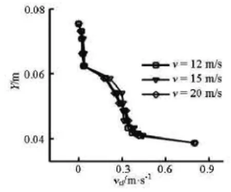
Fig.12 Tangential velocity curve of cuttings in the large annulus at X=0 m
3.2.2 Cutting size
As shown in Figs.13(a)-13(b), another important drilling parameter in the cuttings bed development is the cutting size, and the axial velocity of the cuttings decreases as the cutting size is increased. When the cutting size(D)is below 0.001 m, it has almost no effect on the axial velocity of the cuttings in the large annulus. WhenD is greater than or equal to 0.001 m, the axial peak velocity of the cuttings (vap)in the large annulus decreases, as far as by 3 m/s as the cutting size is increased. The vapin the large annulus at the cutting size of 0.45×10⁻³m is about 1.7 times of that at the cutting size of 5.93×10⁻³m. The cutting size has a significant effect on the axial velocity of the cuttings in the small annulus. The vapin the small annulus decreases, as far as by 4 m/s as the cutting size is increased. The vapin the small annulus at the cutting size of 0.45×10⁻³m is about 5.6 times of that at the cutting size of 5.93×10⁻³m. According to the above analysis, the cuttings settle down in a large extent in the small annulus, where the scree of the small cuttings particles move in saltation with the greater speed of 8.5 m/s-13.9 m/s, and those of the large cutting particles move in the creeping at a lower speed of 1.4 m/s-5.78 m/s. This indicates that small cuttings particles are apparently easier to remove.

Fig.13 Axial velocity distribution of cuttings along the radial line AB at X =0 mfor various cutting sizes

Fig.14 Volume distribution slice of cuttings at X=0 mfor various cutting sizes
Figures 14(a)-14(d) show that the larger the cutting size is, the more easily the cuttings are deposited,and the more difficult it is to remove the scree of the cuttings. The suspended transport is a method of the highest efficiency and the highest speed. Most of the cuttings of D=0.45×10⁻³m and 0.001 m are suspended in the annulus, being blown away by the airflow against gravity, and a small part of them settle down at the lower wall, but move in saltation at the greater speed of 8.5 m/s-13.9 m/s. As the cutting size increases, a decrease in the volume fraction of the suspension cuttings in the large annulus is observed. Only fewer cuttings of D=3.3× 10⁻³mare suspended in the annulus to be blown away by the airflow. Most of them settle down at the lower wall and move in the creeping at a lower speed of 4.5 m/s-5.78 m/s. The cuttings of D=5.93× 10⁻³malmost completely settle down at the lower wall with a volume fraction greater than 0.06, and move in the creeping at a lower speed of 0.1 m/s-1.4 m/s.
Based on these observations, it is recommended to use the cuttings bed impeller or cutting broken tools. The former is used to destroy the cuttings bed, and stir up the deposition of the cuttings at the lower wall. The latter is used to break the cuttings, and the large cuttings will be broken into small size cuttings, to be easily removed.

Fig.15 Axial velocity distribution of cuttings along the radial line AB at X=0 mfor various drill pipe rotations
3.2.3 Drill pipe rotation
The effect of the drill pipe rotation on the cuttings bed development is found to be slight. From Figs.15(a)-15(b), regardless of whether or not the drill pipe rotates, distribution of the axial cuttings velocity along the radial line AB almost always remain consistent. As shown in Fig.16, the effect of the drill pipe rotation on the tangential velocity change is particularly evident. It reaches the maximum at the surface of the drill pipe, and reaches zero at the wall, which is due to the still wall and the rotation of the drill pipe. Compared to the axial velocity, the tangential velocityis smaller and has little effect on the flows of the cuttings in the annulus. From Fig.17, as the drill pipe rotation is increased, the volume fraction of cuttings decreases only a little. Therefore, the drill pipe rotation has almost no effect on the cuttings transport. Taking into account the poor wellbore stability in the gas drilling and the impact of the high rotation on the drill tool life, it is recommended that the drill pipe rotation of 60 r/min should be adopted in gas drilling operations.

Fig.16 Tangential velocity distribution of cuttings along the radial line AB at X=0 m

Fig.17 Average volume fraction curve of cuttings at different moments
3.2.4 Drill pipe eccentricity
From Figs.18(a)-18(b), it can be observed that at the outlet, as the drill pipe eccentricity is increased,the cuttings bed area is increased. The larger the eccentric distance of the drill string is, the smaller the axial velocity of the cuttings in the small annulus is,and the more easily the cuttings settle down at the small annulus. The drill pipe eccentricity can increase the speed of the cuttings in the suspension layer to some extent, but at the same time also increase the cuttings bed area in the lower wall. The peak axial velocity of the cuttings in the small annulus at the drill pipe eccentricity of 0 reaches 13.68 m/s, which is 1.9 times of that at the eccentricity of 0.4. The axial peak velocity of the cuttings in the small annulus decreases by 2 m/s, thus the eccentricity is not conducive to the cuttings transport. From Fig.19, it is seen that as the eccentricity is increased, the volume fraction of cuttings increases significantly over time. Therefore, it is recommended to use the downhole tools with better performance, such as the tapered nipple and the centralizer, to prevent the drill pipe from lying on the wall,thus avoiding the deposition of the cuttings bed at the lower wall caused by the eccentric annulus.

Fig.18 Axial velocity distribution of cuttings along the radial line AB at the outlet

Fig.19 Average volume fraction curve of cuttings at different moments
4. Conclusions
(1) A gas-solid two phase flow simulation model is established to simulate the distribution features and the effect of major drilling parameters in the gas horizontal drilling.
(2) In a range of the parameters of the gas horizontal drilling (the gas injection rate, the cutting size,the volume fraction of cuttings, the drill pipe rotation,etc.), a large number of cuttings settle down before and after the drill pipe connector lying in the wall.
(3) The most effective drilling parameter for the cuttings bed development is the annular gas velocity. The gas velocity directly affects the axial velocity of cuttings, and the greater the gas velocity is, the more easily the cuttings are removed. Under the premise of ensuring the safety of drilling, we might provide sufficient gas, which is conducive to ease the cuttings settlement to some extent.
(4) Another important drilling parameter of the cuttings bed development is the cutting size. As the cutting size is increased, it becomes more difficult to remove the cuttings, and it would be easier for the cuttings to build up a fixed bed. Based on the on-site drilling practice, the cutting size is about 0.45×10⁻³m-5.93×10⁻³m, and the calculations show that under the current drilling operations, there will be a serious cuttings settlement problem when the cutting diameter is greater than 3.3×10⁻³m.
(5) The effect of the drill pipe rotation on the cuttings transport is not significant.
(6) The drill pipe eccentricity is not conducive to the cuttings transport. It is recommended to use the downhole tools with better performance, such as the tapered nipple and the centralizer, to prevent the drill pipe from lying on the wall.
[1] LI Y., KURU E. Numerical modeling of cuttings transport with foam in horizontal wells[J]. Journal of Canadian Petroleum Technology, 2003, 42(10): 54-61.
[2] WANG Zhi-ming, ZHANG Zheng. A two-layer timedependent model for cuttings transport in extended reach horizontal wells[J]. Journal of Hydrodynamics,Ser. A, 2004, 19(5): 676-681(in Chinese).
[3] MO Yue-long, WANG Hua and NIE Ming-hu et al. Discussion on underbalanced horizontal drilling technology[J]. West-China Exploration Engineering, 2008,(6): 55-58(in Chinese).
[4] MENG Ying-feng, LIAN Zhang-hua and LI Hong-jie et al. Research on the cuttings-carried ability in gas horizontal drilling and its application to well baiqian-111H[J]. Natural Gas Industry, 2005, 25(8): 50-53(in Chinese).
[5] THE DEPARTMENT OF ENGINEERING TECHNOLOGY AND MARKET OF CHINA NATIONAL PETROLEUM CORPORATION. Exploration and production company of PetroChina company limited horizontal well technology seminar proceedings[M]. Beijing: Petroleum Industry Press, 2008(in Chinese).
[6] AZIZ T. N., RAIFORD J. P. and KHAN A. A. Numerical simulation of turbulent jets[J]. Engineering Applications of Computational Fluid Mechanics, 2008,2(2): 234-243.
[7] SAINTPERE S., MARCILLAT Y. and BRUNI F. et al. Hole cleaning capabilities of drilling foams compared to conventional fluids[C]. Society of Petroleum Engineers Annual Technical Conference and Exhibition(SPE 63049). Dallas, Texas, USA, 2000, 1-9.
[8] OZBAYOGLU M. E., KURU E. and STEFAN M. et al. A comparative study of hydraulic models for foam drilling[J]. Journal of Canadian Petroleum Technology,2002, 41(6): 52-61.
[9] OZBAYOGLU M. E., MISKA S. Z. and REED T. et al. Using foam in horizontal well drilling: A cuttings transport modeling approach[J]. Journal of Petroleum Science and Engineering, 2005, 46(4): 267-282.
[10] ZHU Xiao-hua, SUN Chao and TONG Hua. Distribution features, transport mechanism and destruction of cuttings bed in horizontal well[J]. Journal of Hydrodynamics, 2013, 25(4): 628-638.
[11] LIOUMBAS J. S., KOLIMENOS C. and PARAS S. V. Liquid layer characteristics in gas-liquid flow in slightly inclined pipes[J]. Chemical Engineering Science, 2009,64(24): 5162-5172.
[12] QUAMRUL H. M., SIAMACK A. S. and BRENTON S. M. Prediction of solid particle erosive wear of elbows in multiphase annular flow-model development and experiment validations[J]. Journal of Energy Resources Technology, 2008, 130(2): 1-10.
[13] NIU Y. Y., LIN Y. C. and CHANG C. H. A further work on multi-phase two-fluid approach for compressible multi-phase flows[J]. International Journal for Numerical Methods in Fluids, 2008, 58(8): 879-896.
[14] CHO H., SHAH S. N. and OSISANYA S. O. A Three segment hydraulic model for cuttings transport in coiled tubing horizontal and deviated drilling[J]. Journal of Canadian Petroleum Technology, 2002, 41(6): 32-39.[15] GRADECK M., LEBOUCHÉ M. Two-phase gas-liquid flow in horizontal corrugated channels[J]. International Journal of Multiphase Flow, 2000, 26(3): 435-443.
[16] GILLIES R. G., SHOOK C. A. Modelling high concentration settling slurry flows[J]. Canadian Journal of Chemical Engineering, 2000, 78(4): 709-716.
[17] ZHU Xiao-hua, JING Jun and TONG Hua. Causes and conditions for reamer blade balling during hole enlargement while drilling[J]. Engineering Applications of Computational Fluid Mechanics, 2012, 6(1): 87-99.
[18] LIU H., FAN J. and YAN R. et al. Experimental study on carrying capacity of cuttings in annulus for air/mist drilling[C]. Society of Petroleum Engineers/Intervention and Coiled Tubing Association (SPE 68500). Beijing, China, 2000, 1-7.
* Project supported by the National Natural Science Foundation of China (Grant No. 51222406, 51004082), the New Century Excellent Talents in University of China (Grant No. NCET-12-1061) and the Youth Scientific Research Innovation Team Project of Sichuan Province (Grant No. 2014TD0025).
Biography: ZHU Xiao-hua (1978-), Male, Ph. D., Professor
杂志排行

水动力学研究与进展 B辑的其它文章
- An effective method to predict oil recovery in high water cut stage*
- Impact of bridge pier on the stability of ice jam*
- Implicit large eddy simulation of unsteady cloud cavitation around a planeconvex hydrofoil*
- Prediction of ship-ship interactions in ports by a non-hydrostatic model*
- Flow hydrodynamics in embankment breach*
- The variations of suspended sediment concentration in Yangtze River Estuary*