泡沫混排解堵数学模型及数值模拟
2015-11-30李兆敏李松岩杜庆军中国石油大学华东石油工程学院山东青岛66580中国石油大学华东地球科学与技术学院山东青岛66580
王 飞,李兆敏,李松岩,杜庆军(.中国石油大学(华东)石油工程学院,山东青岛 66580;.中国石油大学(华东)地球科学与技术学院,山东青岛 66580)
文章编号:1001⁃246X(2015)01⁃0058⁃07
泡沫混排解堵数学模型及数值模拟
王 飞1,李兆敏1,李松岩1,杜庆军2
(1.中国石油大学(华东)石油工程学院,山东青岛 266580;2.中国石油大学(华东)地球科学与技术学院,山东青岛 266580)
建立泡沫井筒流动模型与泡沫地层渗流模型,得到完整的泡沫混排解堵数学模型;利用数值方法对模型进行耦合求解,得到泡沫压力,质量,密度在井筒中的分布及井口井底压力的变化规律.在固定井口回压情况下,得到井底压差的变化规律.结果表明:随着井深的增加,泡沫压力增加,质量减小,密度增加;固定井口回压,井底压差则逐渐变小.
泡沫混排;地层渗流;井筒流动;数学模型;井底压差
0 引言
在钻井,完井,采油等过程中,油藏近井地带常受到不同程度的伤害.造成近井地层污染和堵塞,油井产量下降.目前,根据泡沫流体性质提出的泡沫混排解堵技术能有效地解决此类问题.通过井筒将泡沫注入近井地层,再利用泡沫的可压缩特性将其迅速放喷,从而把近井地带堵塞物携带排出,达到解除堵塞、改善近井地带渗流状况的目的.
此项技术在现场生产中得到了成功应用[1-2],实验研究[3]也有了一定进展,但完善的理论还未建立,现有的模型对于地层渗流未考虑[4-6]或与井筒流动过程分开考虑[7],而数值模拟常采用相关软件[8-9]进行,缺乏准确的结论及认识.本文将注入返排中的井筒管流过程与泡沫在地层的渗流[10-11]过程结合,建立了耦合模型,完善了泡沫混排理论,数值模拟结果可以指导现场应用.
1 物理模型
混排过程分为两个部分:①泡沫注入部分,通过油管将泡沫注入近井地层;②泡沫返排部分,将泡沫从地层沿油管放喷(见图1).

图1 泡沫混排示意图Fig.1 Schematic of foam plug removal
2 数学模型
根据物理模型,泡沫混排数学模型分为两个部分,泡沫注入部分和泡沫返排部分.每个部分又分为两个过程:①是泡沫在井筒中的流动过程;②是泡沫在地层中的渗流过程.建立数学模型就是将这两个过程耦合,然后将两个部分结合,得到整个施工流程上的模型.
2.1 泡沫注入模型建立
2.1.1 井筒管流模型
泡沫在井筒内的流动基于质量守恒方程和动量守恒方程[12-13],假设
1)泡沫流体处于稳定的流动状态;
2)泡沫流体的可压缩性完全取决于泡沫内气体的可压缩性;
3)井筒的温度按地温梯度计算.
根据以上假设,可以列出注入时泡沫流体在井筒中流动的数学模型.
质量守恒方程

动量守恒方程
式中,ρg,ρl为泡沫中气体和液体的密度,kg·m-3;qg,ql为 泡沫中气体和液体的体积流量,m3·s-1;(d p/d H)f=/D为泡沫流体的摩阻压降;(d p/d H)f=-ρfgsinθ为泡沫流体的重力压降;(d p/d H)ac为泡沫流体的加速压降,一般很小,可以忽略不计;ρf为泡沫密度;Vf为泡沫流体的流速,m·s-1;D为井筒直径;θ为管路倾角度.

2.1.2 泡沫渗流模型
泡沫地层中渗流过程可以近似为单相径向流[14-15].泡沫具有暂堵分流特性[16],对于同一小层,根据泡沫圈闭气体和泡沫质量守恒可以得到以下方程.
地层内泡沫前沿半径

气相圈闭拟表皮系数

地层的吸液能力

泡沫体积流量

气体体积流量

泡沫质量

式中,Rf为注入泡沫前沿半径,m;Rw为井筒半径,m;qf为注入地层的泡沫流量,m3·s-1;Γ为注入泡沫质量,小数;ϕ为地层孔隙度,小数;SP为注入气相圈闭拟表皮系数,无量纲;K,Kf分别为地层原始渗透率和地层注入泡沫后渗透率,D;K/Kf反映了泡沫的稳定性,可由实验确定;pw为注入井底压力,MPa;pe为油藏边界压力,MPa;μf为注入泡沫流体黏度,Pa·s;Re为泄油边缘半径,m;S为地层初始表皮系数,无量纲;Swc为束缚水饱和度,无量纲;ql,qg为注入泡沫中液体和气体体积流量,m3·s-1;Te为返排地层温度,K;zg为注入气体压缩因子,无量纲;qgsc为注入泡沫中气体在标准状态下的体积流量,m3·s-1;pgsc为标准状态下的压力,0.1 MPa;Tgsc为标准状态下的温度,273.15 K.
2.1.3 边界条件
在泡沫混排中,注入井口泡沫流体的标方流量保持为定值,返排井口回压保持为定值.
qgsc=const; ql井口=const; p井底(t) =pw(t)(耦合边界).
2.1.4 初始条件
p井底(0) =pe.
将井筒流动模型与泡沫在地层中的渗流模型耦合得到泡沫注入模型.
2.2 泡沫返排模型建立
1)井筒管流模型
与注入部分相同假设,同样可以列出返排时泡沫流体在井筒中流动的数学模型.
质量守恒方程

动量守恒方程

2)泡沫渗流模型
返排时地层内泡沫前沿半径逐渐减小,根据注入后半径得

其中:Qt为注入地层的泡沫量,m3;′为返排地层的泡沫流量,m3·s-1;
与注入部分类似可以列出:
返排气相圈闭拟表皮系数

返排地层的吸液能力

返排泡沫体积流量

返排气体体积流量

返排泡沫质量

3)边界条件
在泡沫混排中,注入井口泡沫流体的标方流量保持为定值,返排井口回压保持为定值.

4)初始条件
将井筒流动模型与泡沫在地层中的渗流模型耦合得到泡沫返排模型.
2.3 辅助方程
1)油管温度按地温梯度计算,倾角按井身结构参数计算.
T=T(H);θ=θ(H).
2)假设注入返排气液质量比不变,即注入标方下气液比与返排标方下气液比相等.

约束条件:井底压力pw(t)小于地层破裂压力pfrac;泡沫基液返排量小于泡沫基液注入量,即∑q′l≤∑ql;返排泡沫前沿半径大于井筒半径,即′≥Rw.
3 模型离散
将注入模型与返排模型在时间和空间上离散,沿井筒分为M段,时间上分为N份,将上述数学模型进行离散.
3.1 泡沫注入模型离散
1)井筒流动模型离散

2)泡沫渗流模型离散

3.2 泡沫返排模型离散
1)井筒流动模型离散

2)泡沫渗流模型离散

4 模型求解
1)根据泡沫注入地层渗流模型,结合初始条件,边界条件,得到井筒井底压力,并作为下一时刻泡沫渗流模型初始条件.
2)由井底压力对井筒进行迭代求解,得到沿井筒压力分布.
3)重复上述步骤,直到注入结束.
4)输出所有时刻沿井筒压力分布,泡沫质量,泡沫密度及地层渗流状况等.
5)将泡沫注入结束参数作为泡沫返排初始条件,根据返排泡沫地层渗流模型,得到井底压力.根据井筒流动模型,计算沿井筒压力分布.结合井口回压,试算泡沫流量.
6)试算结束得到井底压力,作为下一时刻泡沫渗流模型初始条件.
7)重复4)到6),直到返排量等于注入量.
8)输出返排时间,返排井底压差,井筒泡沫流量,泡沫质量,泡沫密度等.
5 算例
根据计算步骤,编制了计算程序.该程序可用于泡沫混排参数设计,确定井口注入压力、返排井底压差、返排时间、气体和液体的流量等关键参数,指导现场的返排作业.下面以一口直井为例,对泡沫流体混排的过程进行了模拟,给出相应的计算结果,并画出了各参数之间相互影响的关系曲线.井地层及油井施工参数如表1所示.
5.1 注入部分计算结果分析
图2可以看出,随着井深的增加,井筒压力逐渐增加.反应了注入中泡沫沿井筒受重力及摩阻压降的综合影响.
图3可以看出,泡沫质量随着井深增加,逐渐减小,这是由于随井深增加压力增加,泡沫流体中气体流量减小,体现了泡沫的可压缩性.
图4可以看出,随着井深增加,泡沫密度逐渐增加,这是由于压力随井深的增加,泡沫中气体逐渐被压缩,液相所占体积分数增加.
图5可以看出注入泡沫时井口及井底压力逐渐增加,开始阶段增加迅速,最终逐渐趋于平缓.这是泡沫对于地层的封堵作用及泡沫破灭共同导致的.
5.2 返排部分计算结果分析
图6可以看出,固定井口回压,井底返排压差逐渐减小.在返排开始阶段,迅速放喷造成井底压差处于很高的状态,随着返排的进行,压力逐渐趋于平衡.
图7可以看出,固定井口回压,井口和井底泡沫返排量变化不大,呈略微减小趋势.泡沫流量主要包含气体和液体两部分流量,在返排过程中,井底压差的变化导致泡沫流量的变化,而在固定井口回压下,考虑到泡沫摩阻压降的变化范围不大,泡沫流量基本也稳定在一定的范围.
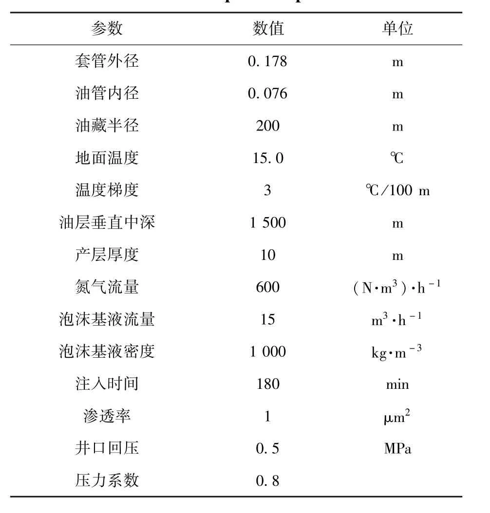
表1 地层及油井施工参数Table 1 Formation and operation parameters of a well

图2 注入泡沫压力沿井筒变化Fig.2 Evolution of foam injection pressure along wellbore

图3 注入泡沫质量沿井筒变化Fig.3 Evolution of foam quality along wellbore

图4 注入泡沫密度沿井筒变化Fig.4 Evolution of foam density along wellbore

图5 注入泡沫压力随时间变化Fig.5 Evolution of foam injection pressure
图8和9可以看出,泡沫流量和质量随着井深增加,逐渐减小,这是由于随井深增加压力增加,泡沫流体中气体流量减小,体现了泡沫的可压缩性.
图10可以看出,随着井深增加,泡沫密度逐渐增加,这是由于压力随井深的增加,泡沫中气体逐渐被压缩,液相所占体积分数增加.整个井筒内泡沫的密度要远远小于水的密度,这充分体现了泡沫流体低密度的特点.

图6 返排井底压差随时间变化Fig.6 Evolution of bottomhole differential pressure during foam flowback

图7 泡沫返排量随时间变化Fig.7 Evolution of foam rate during foam flowback
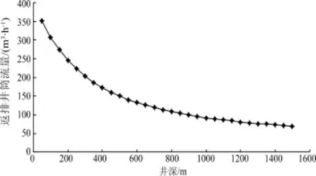
图8 返排泡沫流量沿井筒变化Fig.8 Evolution of flow rate during foam flowback along wellbore
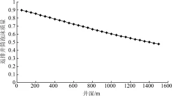
图9 返排泡沫质量沿井筒变化Fig.9 Evolution of foam quality during foam flowback along wellbore

图10 返排泡沫密度沿井筒变化Fig.10 Evolution of foam density during foam flowback along wellbore
6 结论
1)建立了泡沫混排数学模型,计算得到了泡沫混排过程注入及返排中,井筒内压力,泡沫流量,泡沫质量,泡沫密度的分布,并得到了随着注入时间的增加,井口及井底压力的变化,特别在固定返排井口回压的情况下,得到了返排井底压差及返排时间.可以对混排过程进行设计.
2)泡沫混排中,随着井深的增加,注入及返排中沿井筒压力逐渐增加;沿井筒泡沫质量及流量逐渐减小;沿井筒泡沫密度逐渐增加.随着注入过程的进行,井口及井底压力增加,最终趋于平缓,施工时可以据此控制井口及井底压力.返排时,固定井口回压,井底压差开始一段时间稳定在较高值,之后迅速降低,现场施工中,返排放喷开始阶段需要严格监控.
[1] Price B P,Gothard B.Foam⁃assisted lift⁃importance of selection and application[C].SPE 106465,2007.
[2] Yang J,Siddiqui S.The use of foam to improve liquid lifting from low⁃pressure gas wells[P].PETSOC⁃99⁃126⁃P.
[3] Chen Z,Ahmed R M,Miska S Z,et al.Experimental study on cuttings transport with foam under simulated horizontal downhole conditions[C].SPE 99201,2006.
[4] 杨肖曦,李松岩,林日亿,等.泡沫流体携砂能力的数值模拟[J].中国石油大学学报(自然科学版),2006,30(3):89-96.
[5] Duan Mingqin,Miska Stefan,Yu Mengjiao,et al.Experimental study and modeling of cuttings transport using foam with drillpipe rotation[C].SPE 116300,2008.
[6] 李兆敏,王冠华,曹小朋.泡沫混排解堵技术研究及应用[J].西南石油大学学报(自然科学版),2010,32(2):178-181.
[7] 曹小朋.泡沫混排解堵的理论研究及应用[D].青岛:中国石油大学(华东),2008.
[8] 万里平,何保生,唐洪明,等.冲砂洗井泡沫携砂规律数值模拟研究[J].西南石油大学学报(自然科学版),2013,35 (4):101-106.
[9] 袁照永.水平井环空泡沫携岩流动规律研究[D].青岛:中国石油大学(华东),2009.
[10] 王玉斗,李茂辉,温科扬,等.泡沫渗流激励及渗流模型研究[J].石油钻探技术,2010,38(4):104-107.
[11] Sim joo M,Iran,Zitha P L J.Effects of oil on foam generation and propagation in porousmedia[C].SPE 165271,2013.
[12] 张小宁,李根生,黄中伟,等.泡沫钻井液在井筒中的流动与传热[J].石油学报,2010,31(1):134-138.
[13] 李松岩,李兆敏,林日亿.泡沫举升排酸过程井筒压力温度数学模型研究[J].西南石油大学学报(自然科学版),2009,31(2):59-63.
[14] 李松岩.氮气泡沫分流酸化工艺技术研究[D].青岛:中国石油大学(华东),2009.
[15] 周生田,李兆敏,王飞.水平井泡沫酸化分流数值模拟[J].石油学报,2012,33(3):448-452.
[16] 李兆敏,孙茂盛,林日亿,等.泡沫封堵及选择性分流实验研究[J].石油学报,2007,28(4):115-118.
Received date: 2014-01-14;Revised date: 2014-06-10
Article ID:1001⁃246X(2015)01⁃0065⁃10
Influence of Fem tosecond Laser Chirp on Optical Limiting
and Dynam ical Two⁃photon Absorption of 4,4'⁃bis(di⁃n⁃butylam ino)stilbene Com pounds
Abstract: Optical limiting(OL)and dynamical two⁃photon absorption(TPA)of 4,4'⁃bis(di⁃n⁃butylamino)stilbene(BDBAS)molecules in chirped femtosecond laser pulses are studied by solving Maxwell⁃Bloch equationswith an iterative predictor⁃corrector finite⁃difference time⁃domain(FDTD)method.It shows that both sign and magnitude of chirp rate influence greatly spectrum evolution and OL behavior.Spectra exhibit obvious carrier frequency shifts depending on sign of chirp rate,blue shift for positive chirp rate and red shift for negative chirp rate.As absolute chirp rate increases,shift becomesmore obvious,OL window gets narrower and saturation of output intensity becomes greater.Interestingly,self⁃induced transparency(SIT)appears as a negative chirp rate reduces to a certain value(-0.025 fs-2).Dynamical TPA cross section is reduced as chirp effect is considered.It provides a method for controlling nonlinear optical absorptions.
Key words: two⁃photon absorption;optical limiting;chirped pulse;organicmolecule
0 Introduction
With remarkable progress in ultrashort and ultraintense laser technology,it is possible to generate precisely defined laser pulses[1]which brings a vast variety of investigations in the light⁃matter interaction[2-5]and leads to great potential of applications[6].Among all of the applications,optical limiter,whosemajormechanism is dynamical two⁃photon absorption(TPA),hasmotivated an extensive research in order to protect delicate sensors,especially human eyes.On the basis of quantum approaches at ab initio level,the TPA cross section of a molecule was theoretically calculated[7-8].This TPA cross section is normally noted as static since it is only referred to the molecule itself.When the TPA cross section of a molecular system is measured,there exists interaction between the molecule and laser.Thus,one should solve the combined Maxwell⁃Bloch equations[6,9-10]to simulate correctly experimental results and explore nonlinear optical processes. As a result,the TPA cross section performs as a dynamical value because it is related to laser parameters.
Considering that a laser pulse usually has a large frequency chirp that may change characteristics of the pulse significantly[11-12],one expect that the laser chirp would have influence on nonlinear optical properties of molecules.In the last decades,chirped laser pulses have been widely applied to generate high⁃order harmonic(HHG)[13],transfer population[14],and transform multiphoton between Rydberg states[15],etc.Desaix et al[16]studied chirped soliton pulses propagating in optical nonlinear Kerr media,indicating obvious influences on properties ofasymptotically emerging solitons by the initial chirp.Moreover,Centinietal[17]measured signal and group velocities of chirped pulses propagating through a GaAs cavity,which showing substantial modification of the group velocity of pulse by the chirp.Song et al[18]investigated theoretically coherent control of spectra with chirped femtosecond laser pulses propagating in a two⁃level⁃atom medium.They found that the sign and magnitude of the chirp rate have obvious effects on the spectral feature.
To the best of our knowledge,there are few works to study influence of chirp on OL properties and dynamical TPA cross sections of organic compounds.In this paper,taking the BDBAS compound as the medium reported by Ehrlich[19],we investigate spectra of chirped femtosecond laser pulses and OL behaviors of the compounds by solving Maxwell⁃Bloch equations using an iterative predictor⁃corrector FDTDmethod[20].Chirp effecton TPA cross section is analyzed further.
1 Theoreticalmethods
1.1 M axwell⁃Bloch equations of a three⁃level system
Based on a semiclassical theory for interaction between laser pulses and molecules,electromagnetic radiation is described classically by Maxwell equations,and themolecular system is treated quantum mechanically with Bloch equations.The density matrix equation with relaxation effect is written as

here,Γnmgives the rate per atom atwhich population decays from level m to level n,andγnmgives relaxation rate of the density matrix elementρnm.is Hamiltonian of the system,which can be expressed as the sum of Hamiltonian of the field⁃free moleculeand the interaction Hamiltonian H^′.Within the dipole approximation,it can be written as

Settingρ01=(u0+i v0)/2,ρ12=(u1+i v1)/2,ρ02=(u2+i v2)/2,we get Bloch equations for the three⁃level system ∂u


where dmn=dnm(m,n=0,1,2)are the permanent electric dipolemoments(m=n)or the transition electric dipolemoments(m≠n)of the molecule,andћωmnis the excitation energy between the states m and n.
We assume that the incident electromagnetic field polarizes along the x axis and propagates along the z axis to an input interface at z=0.Then the Maxwell equations take the form

whereμ0andε0are the permeability and permittivity of free space,respectively.
The Maxwell and the Bloch equations are coupled to each other by themacroscopic polarization Px,

where N is themolecular density.
1.2 Dynam ical TPA cross section
In the absence of significant recombination,diffusion and thermal,the differentialequation that describes propagation of pulses in the presence of linear and TPA can be written as[21]

where I is the field intensity,αdenotes the linear absorption coefficientandβis the TPA coefficient. The analytical solution of Eq.(6)is

As one knows,the TPA coefficient depends on the input intensity I0[22].If I0is smaller than the saturation absorption intensity,the TPA coefficientβcan be assumed as a linear function of I0[23],

whereβ0is the steady⁃state TPA coefficient.Input Eq.(8)into(7),one can see that the inverse transmission 1/T is a quadratic function of the input field intensity I0,

αandβ0can thus be estimated from Eq.(9).Themolecular TPA cross sectionσtpis related toβ0by

where hνis the input photon energy.
2 Results and discussions
As shown in Fig.1,BDBAS is a typical one⁃dimensional symmetrical conjugated organic molecule.The time⁃dependent DFT/B3LYP method implemented in DALTON package[24]is employed to obtain the excitation energy Enand the dipolemoment dmnof themolecule.The 6⁃31G basis set is chosen for all calculations.It is shown in Table 1 that thismolecule has only one charge transfer state in low energy region,which is the first excited state S1withδop=1.630.The transition dipolemoment between S1and the fourth excited state S2ismuch larger(d14=4.154×10⁻²⁹C·m)than the others.ab initio calculations show that the fourth excited state S2has the maximum TPA cross section in the low energy region.The excitation energies of S1and S2are 3.408 eV and 4.206 eV,respectively.The permanent dipole moments are approximately equal to zero because of symmetry of themolecule.When the interaction between themolecule and ultrashortpulse in the low energy region is considered,a cascade three⁃level system including the ground state S0,the first excited state S1and the fourth excited state S2ismodeled as shown in Fig.1.

Fig.1 Molecular structure of BDBAS(left)and transitions(right)

Table 1 Excitation energy En,oscillator strengthδopand dipolemoment dmnof the first five excited states
We choose the initial chirped electric field with a hyperbolic⁃secant functional for Ex(z=0,t)=F0sech[1.76(t-z0/c)/ ]cos[ω0t+χt2/2],where F0is the peak amplitude of the inputelectric field, is the fullwidth at halfmaximum(FWHM)of the pulse intensity envelope,which is set as a few femtoseconds,andχis the chirp rate.The choice of z0ensures that the pulse penetrates negligibly into themedium at t=0.Themolecule is assumed in its ground state before the light is turned on,i.e.,ρ00(t=0)=1,ρ11(t=0)=ρ22(t=0)=0.Themolecular density is taken as N=7.0×1025m-3.The decay rates of the densitymatrix elementsγnmcan be chosen as 1.0× 10¹³s-1,while the decay rates of excited statesΓ01,Γ12andΓ02are assumed equal to 1.0×10⁹s-1,1.0×1012s-1and 0[25],respectively.The time and space incrementsΔt andΔz are chosen to ensure cΔt≤Δz[26].
2.1 Two⁃photon resonant propagation of fem tosecond pulse
Frequency of the incident ultrashort pulseω0is taken as half of the frequency between S0and S2states,namely,ω0=ω20/2.Taking FWHM of the incident pulse as 5 fs,we simulated temporal evolution of pulses with different input peak amplitudes F0=4.0×10⁹V·m-1,6.0×109V·m-1and 8.0×10⁹V·m-1for chirp ratesχ=0,0.002 5 fs-2and-0.002 5 fs-2,respectively(Fig. 2).As one can see in Fig.2,the pulses increase area by splitting,not by pulse broadening as in the long pulse cases,which is in agreementwith a previouswork[27].Thismeans that the traditional area theorem based on the slowly⁃varying envelope approximation and rotatingwave approximation[28]is invalid in describing an ultrashort pulse propagation accurately.As the input peak amplitudes increases,the splitbecomes obvious.Compared with the chirp free case,the splits of chirped pulses are weaker,which is consistentwith the two⁃level case[18].When a chirp rate exists,themain pulse has little variation,and the subpulse intensity becomes weaker.The time⁃delay between the main pulse and subpulse turns longer compared with the case without a chirp rate.
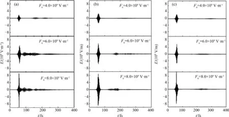
Fig.2 Evolution of electric fields with different input peak amplitudes(a)χ=0,(b)χ=0.002 5 fs-2,and(c)χ=-0.002 5 fs-2with pulse width 5 fs at propagation distance of 7.0μm
Corresponding spectra of Fig.2 are shown in Fig.3.One can see that except for the base frequencyω0,lower and higher frequencies appear mainly due to self⁃phase modulation(SPM)during the propagation of pulse,such asω21,ω10,ω10+2ω21,3ω0and 5ω0.The odd harmonic components(3ω0and 5ω0)appear for the symmetry compounds with a strong TPA process,while the even harmonic components are restrained.With the enhancement of peak amplitudes,the spectra display more components.When chirp rate is considered,the spectra of chirped pulses exhibit obvious shift of carrier frequency during propagation in medium depending on the sign of chirp rate,namely,blue shifts for positive chirp rates and red shifts for negative cases,which is consistentwith previous results[18].
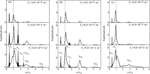
Fig.3 Corresponding spectra in Fig.2(a)χ=0,(b)χ=0.002 5 fs-2,and(c)χ=-0.002 5 fs-2.
In order to further elucidate the influence of chirp on ultrashort pulse propagation,we consider different chirp rates.Fig.4(left)shows a chirped pulse of F0=4.0×10⁹V·m-1withχ=±0.005 fs-2andχ=±0.025 fs-2,propagating through BDBAS at respective distances of0 and 14.0μm.One can see that as absolute value of the chirp rate increases,the intensity of main pulse increases obviously,while the intensity of subpulse components decreases.Corresponding spectra are shown in Fig.4(right).One can see that the spectra shift ismore evident for pulse with a larger absolute value of chirp rate.Moreover,higher and lower frequency components(ω21andω10)disappear for a chirped pulse withχ=±0.025 fs-2.The center frequency deviates further from TPA resonant frequencyω20/2 as the absolute value of chirp rate increases,leading to weaker TPA from S0to S2and thus smaller population of S2.Specially,when the chirp rate takes-0.025 fs-2,themedium becomes approximately transparent to pulse.

Fig.4 Evolution of electric fields(left)at distances of 0(solid line)and 14.0μm(dash line)and corresponding spectra(right)at 14.0μm with different chirp rates(F0=4.0×10⁹V·m-1, =5 fs)
In order to further observe this phenomenon,Fig.5 shows a chirped pulse of F0=4.0×10⁹V· m-1withχ=-0.025 fs-2propagating through BDBAS at respective distances of 0,3.5μm,7.0μm,10.5μm,14.0μm and 17.5μm(Fig.5(a))along with the corresponding spectra(Fig.5 (b)).One can see that the shape of pulse is quite stable and no additional frequency appears.This can be explained by the resonant frequency shiftandmuch weak absorption during pulse propagating process.

Fig.5 (a)Chirped pulse ofχ=-0.025 fs-2propagating through BDBAS at respective distances of 0μm (solid line),3.5μm(dash line),7.0μm(dot line),10.5μm(dash dot line),14.0μm(dash dot dot line)and 17.5μm(short dash line),and(b)corresponding spectra(F0=4.0×10⁹V·m-1, =5 fs)
2.2 OL and dynam ical TPA cross section
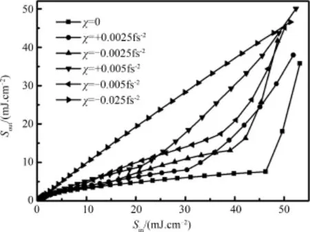
Fig.6 Output fluence Soutat z=7.0μm versus input fluence Sinof a 5 fs pulses
To illustrate influence of chirp rate on OL ability,we present output fluence Soutat z=7.0μm as a function of input fluence Sinof 5 fs pulses with different chirp ratesχ=0, ±0.002 5 fs-2, ± 0.005 fs-2and-0.025 fs-2in Fig.6.As shown in Fig.6,one can see that the chirp rate has an obvious influence on OL in both OL window and higher output saturation intensity.When the absolute value of chirp rate increases,the medium shows a narrow OL window and higher output saturation intensity,showing weaker OL ability.Specially,when the chirp rate reaches-0.025 fs-2,the medium turns transparent,meaning breakdown of OL behavior.This phenomenon is due to the resonant frequency shift caused by chirp rate,which results in much weak absorption from ground state S0to the maximum TPA state S2.
Dependence of dynamical TPA cross sectionσtpon pulse width in femtosecond time domain with different chirp rates ata distance of7.0μm is shown in Fig.7.One can see that the TPA cross section increases as thewidth of the input pulse is broadened.The TPA cross sections is obtained as 1 145.3 GM(1 GM=1×10-50cm4s/photon)for chirp free pulse width of 5 fs at a distance of7.0μm,which is in the same order of magnitude with the static TPA cross sectionσtp=1 430 GM.The calculated value is smaller than the experiment result of σtp=9 300 GM[19].The discrepancy mainly results from the experimental condition with pulse duration of 5 ns andλ=600 nm under which a two⁃step TPA process takes place.Furthermore,the TPA cross section is reduced by the chirp,and theχ=0.002 5 fs-2pulse shows a larger TPA cross section than theχ=-0.002 5 fs-2pulse.Therefore,both sign and magnitude of pulse chirp rates should be considered when calculating TPA cross sections of different pulses.

Fig.7 Dependence of TPA cross sectionσtpon pulse widths and chirp rates at a distance of 7.0μm
3 Conclusions
In conclusion,we investigate influence of chirp rates on OL and dynamical TPA in a cascade three⁃level medium BDBAS theoretically by solving Maxwell⁃Bloch equations using an iterative predictor⁃corrector FDTDmethod.It is demonstrated that both sign and magnitude of the chirp rate influence spectra and nonlinear properties of the medium crucially.The OL ability breaks down as magnitude of the negative chirp rate is larger than 0.025 fs-2.The OL behavior ismore obvious and the dynamical TPA cross section ismuch larger for a positive chirp rate laser compared with negative one.It shows thatboth sign andmagnitude should be taken into consideration when nonlinear optical properties of medium are measured and simulated.Our investigation predicts a way to control nonlinear optical absorption by changing chirp rate.
[1] Kong L J,Zhao L M,Lefrancois S,et al.Generation ofmegawatt peak power picosecond pulses from a divided⁃pulse fiber amplifier[J].Opt Lett,2012,37(2):253-255.
[2] Liu Z B,Fan X J.Phase correlation in propagation effect of a doppler broadening quasi⁃Λtype four⁃level system[J].Chinese JComput Phys,2012,29(6):881-890.
[3] Tan X,Wang L,Wang Z D,et al.Population of dense V⁃type three⁃level medium in few⁃cycle laser pulses[J].Chinese JComput Phys,2009,26(5):773-780.
[4] Zhou Y,Miao Q,Wang C K.Effect of Lorentz local field correction on propagation of ultrashort laser pulse in one⁃dimensional para⁃nitroaniline(PNA)molecules[J].Chinese Phys B,2011,20(4):044205(1-5).
[5] Wang L,Wang Z D,Lian B,et al.Spatial distribution of few⁃cycle laser pulses propagating in a ladder⁃type three⁃levelmedium[J].Chinese JComput Phys,2011,28(1):81-86.
[6] Liu JC,Wang C K,Gel'mukhanov1 F.Optical limiting of short laser pulses[J].Phys Rev A,2007,76 (5):053804(1-6).
[7] Sałek P,Vahtras O,Helgaker T,et al.Density⁃functional theory of linear and nonlinear time⁃dependent molecular properties[J].JChem Phys,2002,117(21):9630-9645.
[8] Ding H J,Sun J,Zhang Y J,et al.Solvent effects on one⁃and two⁃photon optical properties of a novel2,2':6',2”⁃terpyridine⁃based chromophore[J].JAt Mol Sci,2013,4(4):349-356.
[9] Wang C K,Zhao P,Miao Q,et al.Optical limiting and dynamical two⁃photon absorption of organic compounds for a nanosecond pulse[J].JPhys B:At Mol Opt Phys,2010,43(10):105601(1-5).
[10] Zhou Y,Miao Q,Sun Y P,et al.Solvent effect on dynamical TPA and optical limiting of BDMAS molecularmedia for nanosecond and femtosecond laser pulses[J].JPhys B:AtMol Opt Phys,2011,44 (3):035103(1-7).
[11] Zheng H J,Liu S L,Xu JP.Research on nonlinear propagation of chirped exponential pulses[J].Stud On Opt Commun,2007,2(140):11-41.
[12] Zheng H J,Liu S L,Lin Xin,et al.Effect of initial frequency chirp on the linear propagation characteristics of the hyperbolic secant optical pulse[J].Acta Phys Sin,2007,56(4):2286-2292.
[13] Lee D G,Kim JH,Hong K H,et al.Coherent control of high⁃order harmonicswith chirped femtosecond laser pulses[J].Phys Rev Lett,2001,87(24):243902(1-4).
[14] Netz R,Nazarkin A,Sauerbrey R.Observation of selectivity of coherent population transfer induced by optical interference[J].Phys Rev Lett,2003,90(6):063001(1-4).
[15] Conover CW S,Doogue M C,Struwe F J.Chirped⁃pulse multiphoton transitions between Rydberg states [J].Phys Rev A,2002,65(3):033414(1-8).
[16] Desaix M,Helczynski L,Anderson D,et al.Propagation properties of chirped soliton pulses in optical nonlinear Kerrmedia[J].Phys Rev E,2002,65(5):056602(1-7).
[17] Centini M,Bloemer M,Myneni K,etal.Signal velocity and group velocity for an optical pulse propagating through a GaAs cavity[J].Phys Rev E,2003,68(1):016602(1-4).
[18] Song X H,Gong SQ,YangW F,et al.Coherent control of spectra effectswith chirped femtosecond laser pulse[J].Opt Commun,2004,236(1):151-157.
[19] Ehrlich JE,Wu X L,Lee I⁃Y S,et al.Two⁃photon absorption and broadband optical limiting with bis⁃donor stilbenes[J].Opt Lett,1997,22(24):1843-1845.
[20] Ziolkowski RW,Arnold JM,Gobny D M.Ultrafast pulse interactionswith two⁃level atoms[J].Phys Rev A,1995,52(4):3082-3094.
[21] Bhawalkar JD,He G S,Prasad P N.Nonlinearmultiphoton processes in organic and polymeric materials [J].Rep Prog Phys,1996,59(9):1041-1070.
[22] He G S,Zheng Q D,Baev A,et al.Saturation ofmultiphoton absorption upon strong and ultrafast infrared laser excitation[J].JAppl Phys,2007,101(8):083108(1-6).
[23] Sun Y P,Liu J C,Wang C K.Effect of time⁃dependent ionization on dynamical two⁃photon absorption cross sections ofmolecularmedia[J].Acta Opt Sin,2009,29(6):1621-1625.
[24] DALTON.A molecular electronic structure program[CP/OL].Dalton 2013.http://dalton⁃program.org/. [25] Gavrilyuk S,Polyutov S,Jha PC,et al.Many⁃photon dynamics of photobleaching[J].JPhys Chem A,2007,111(47):11961-11975.
[26] Taflove A,Brodwin M E.Numerical solution of steady⁃state electromagnetic scattering problems using the time⁃dependent Maxwell's equations[J].Micro Theo Tech,1975,23(8):623-630.
[27] Xiao J,Wang Z Y,Xu Z Z.Area evolution of a few⁃cycle pulse laser in a two⁃level⁃atom medium[J]. Phys Rev A,2002,65(3):031402(1-4).
[28] Mccall S L,Hahn E L.Self⁃induced transparency[J].Phys Rev,1969,183(2):457-485.
M athematical M odel and Numerical Simulation of Foam Plug Removal
WANG Fei1,LIZhaomin1,LISongyan1,DU Qingjun2
(1.College ofPetroleum Engineering,China University ofPetroleum,Qingdao 266580,China;
2.School ofGeosciences,China University of Petroleum,Qingdao 266580,China)
With amodel of foam wellbore flow and a model of foam seepage flow,a mathematicalmodel of foam plug removal is given.Themodel is solved with numerical method.Distributions of foam pressure,foam quality,foam density along wellbore and wellhead and bottom pressure are discussed.Furthermore,variation of bottom hole differential pressure is given as wellhead back pressure is fixed.It shows that as foam pressure and density increases,foam quality decreases with increase of well depth and bottom hole differential pressure declines.
foam plug removal;seepage flow;wellbore flow;mathematicalmodel;bottomhole differential pressure
ZHANG Yujin,ZHANG Qiuyue,SONG Yuzhi,WANG Chuankui
(College ofPhysics and Electronics,Shandong Normal University,Jinan 250014,China)
O437;O561.1 Document code:A
TE319
A
2014-01-14;
2014-06-10
国家高科技研究发展计划(863计划)(2013AA064801)和国家自然科学基金青年基金(11102236)资助项目
王飞(1988-),男,博士生,从事泡沫流体模拟计算及在油田中的应用等研究,E⁃mail:goodboygreatman@163.com
Received date:2014-01-08;Revised date:2014-03-30
Foundation item s:Supported by 973 Program(2011CB808100)
Biography:Zhang Yujin(1989-),female,PhD,major in molecular photonics,E⁃mail:zhangyujin312@163.com
