Effect of structure parameters of the flow guide vane on cold flow characteristics in trapped vortex combustor*
2015-11-25WANGZhikai王志凯ZENGZhuoxiong曾卓雄LIKai李凯XUYihua徐义华
WANG Zhi-kai (王志凯), ZENG Zhuo-xiong (曾卓雄), LI Kai (李凯), XU Yi-hua (徐义华)
1. China Aviation Powerplant Research Institute, Aviation Industry Corporation of China, Zhuzhou 412002,China, E-mail: nhwzk12@126.com
2. College of Power and Mechanical Engineering, Shanghai University of Electric Power, Shanghai 200090,China
3. School of Aircraft Engineering, Nanchang Hangkong University, Nanchang 330063, China
Effect of structure parameters of the flow guide vane on cold flow characteristics in trapped vortex combustor*
WANG Zhi-kai (王志凯)1, ZENG Zhuo-xiong (曾卓雄)2, LI Kai (李凯)3, XU Yi-hua (徐义华)3
1. China Aviation Powerplant Research Institute, Aviation Industry Corporation of China, Zhuzhou 412002,China, E-mail: nhwzk12@126.com
2. College of Power and Mechanical Engineering, Shanghai University of Electric Power, Shanghai 200090,China
3. School of Aircraft Engineering, Nanchang Hangkong University, Nanchang 330063, China
2015,27(5):730-737
The cold flow characteristics are investigated to show the effect of the structural parameters of the flow guide vane on the trapped vortex combustor (TVC). The results show that the structural parameters have significant effects on the TVC. As a/H increases, the total pressure loss, the wall shear stress at the bottom of the cavity and the turbulent intensity in the main combustion zone increase.b/Bdoes not have a significant effect on the cavity flow structure and the total pressure loss, and the wall shear stress at the bottom of the cavity increases asb/Bincreases. There is no significant increase of the turbulent intensity with the increase ofb/B . The increase of c/L has little effect on the total pressure loss, and it is not conducive to a stable combustion. As c/L increases, the wall shear stress at the bottom of the cavity decreases. When a/H =0.4,b/B =0.4,c/L=0.1, a desirable dual-vortex structure is formed with an acceptable pressure loss to achieve a stable combustion. Moreover, to ascertain that the flame is stable for different values ofVmawith the optimal structural parameters, the effect of Vmaon the flow field is discussed. Results suggest that the dual-vortex structure has no relationship with the increase ofVma. Furthermore, an unsteady simulation is conducted to show the generation and the development of the dual-vortex.
trapped vortex combustor (TVC), dual-vortex, flow guide vane, structural parameters, numerical simulation
Introduction
The stable combustion with the fuel-lean operation and a high efficiency in aircraft engines is an issue that has received an extensive attention in recent years. The trapped vortex combustor (TVC) is a new concept for gas turbine engines with high performance,low total pressure loss, low emissions and improved pattern factor[1,2], in which a cavity is employed for the vortex stabilization. The stable combustion is achieved by the use of low velocity recirculation zones to provide a continuous source of ignition mixing hot products with the incoming fuel and air[3-8]. Some new generations of the TVC have been developed since it was first proposed by Hsu et al.[9-11].
In the third generation, the studies of the TVC indicate that the cavity injection strategies play a major role in the flame stability. Meyer et al.[12]and Stone and Menon[13]investigated the cavity injection in the TVC. These studies show that a dual-vortex structure can be formed in the cavity with the fuel injecting from the front wall of the cavity and the air injecting from the rear wall of the cavity. Xing et al.[14]studied the dual-vortex in the cavity with the PIV measurements and the CFD. The results show that there is an optimal value for the afterwall-air speed to enhance the stability of the dual-vortex. Zhang et al.[15]studied the lean-blow-out performance of the double/fuel-leanTVC with experiments by changing the value of Ma and the temperature and some structural parameters. Fan et al.[16]investigated the effect of the dual-vortex on the emissions of the combustor, and the results show that the dual-vortex structure can be observed when the combustor is operating under the condition of low emissions. Furthermore, Meyer et al.[12]pointed that the dual-vortex structure in the cavity is the best for a good combustor performance.
To achieve a dual-vortex structure in the cavity,many experimental and numerical investigations were carried out in recent few years. Most of them[12-16]relied on the fuel injecting from the front wall of the cavity and the air injecting from the rear wall of the cavity. The cavity air has to reach the face of the front wall to generate the dual-vortex structure, which requires that the cavity length is not too long, and a smaller ignition zone will be formed. Meanwhile, the rear wall air jets of the cavity are close to the mainstream flow, and the jets can easily be affected by the mainstream flow, which opposes the cavity air jets,thereby reduces its tendency to reach the opposite cavity face and establish the desirable vortex. It is a challenge to control the effect of the mainstream on the cavity jets and Agarwal and Ravikrishna[17]proposed a strategy in 2010 to do so. This strategy involves placing an L-shaped flow guide vane at the leading edge of the cavity to divert a small portion of the mainstream flow along the cavity wall. The TVC with a flow guide vane leads to the formation of a desirable dualvortex in the cavity. The underside vortex acts as a pilot while the upside vortex enhances the mass and energy transport between the mainstream flow and the cavity.
However, the effect of the flow guide vane structural parameters on the combustor is an issue to be further studied. The vortex structures and the flow characteristics of the TVC are sensitive to the structural parameters of the flow guide vane. Hence, it is necessary to study the structural parameters of the flow guide vane to discover the optimal structural parameters, and to improve the performance of the TVC. Moreover, in order to ascertain whether there will be a desirable dual-vortex structure in the cavity for various mainstream velocities, the effect of the mainstream velocities on the flow fields is analyzed in detail. Finally, to have a better picture of the generation and the development of the dual-vortex in the cavity, an unsteady simulation is conducted.
1. Geometry of model
Figure 1 shows the geometric model of the TVC with a flow guide vane. The combustor is 0.2 m in length, the flow guide vane is 0.001 m in thickness. H =0.02mis the depth of the inlet, so the size of the inlet face is 0.02m×0.02m.B =0.03mis the depth of the cavity,L =0.036mis the length of the cavity. Structure parameters (a,b,c)of the flow guide vane are marked in Fig.1. In this paper,a is the distance from the vane to the upper surface of the cavity,b is the length of the vane inside the cavity,c is the distance from the vane to the front surface of the cavity. Details of the structure parameters and various mainstream velocities (Vma)are listed in Table 1.

Fig.1 The geometric model of TVC

Table 1 Structure parameters and various Vma
2. Boundary condations
Numerical simulations are performed by solving the incompressible Navier-Stokes equations and the realizable k-εmodel is adopted as the turbulence model. The method of coupling the pressure and the velocity is the SIMPLE, the second-order central difference scheme is used for the diffusion terms, and the second-order upwind differencing scheme is used for the convective terms. The boundary conditions include the velocity inlet, the pressure outlet and the noslip wall boundary.
In order to obtain the optimal structural parameters of the flow guide vane,Vma=50m/sis adopted at the inlet boundary. Moreover, in this paper, the effects of Vmaon the TVC are analyzed when the optimal structural parameters of the flow guide vane are taken.
3. Results and discussions
The comparison of the total pressure lossδ∗be-tween the experimental results[17]and the numerical simulation results when a/H=0.1is shown in Fig.2,where a good agreement is evident. Moreover, the relative errors maintain within 5%. Thus, the geometric model and the boundary conditions in this paper are acceptable.

Fig.2 Comparison of experimental and numerical total pressure loss when a/H=0.1

Fig.3 Effect of a/Hon flow fields of center section
3.1 Effect ofa/Hon characteristics of TVC
Figure 3 shows the effect ofa/Hon the flow fields at the TVC center section, which indicates that a dual-vortex structure is formed in the cavity for each a/H, which means that a dual-vortex might be formed even without any cavity air injection when there is a flow guide vane at the leading edge of the cavity. Furthermore, asa/Hincreases, the velocity in the main combustion zone increases accordingly. Higher velocity and higher momentum in the main combustion zone will enhance the fuel-air mixing and improve the TVC performance.
When a/H=0.2, the dual-vortex is smaller than those in other cases. Increasinga/Hto 0.4, the underside vortex in the cavity becomes larger and a small vortex appears in the downstream of the TVC,which will lead to a larger pressure loss. Whena/H continues to increase, reaching a large number as a/ H=0.8, as shown in Fig.3, the underside vortex develops beyond the cavity, and the air velocity around the underside vortex increases significantly, all of which may break the stable combustion in the cavity. In addition, the newly generated vortex in the downstream of the TVC becomes larger with the increase of a/H. Finally, the vortex is large enough, which leads to the formation of a low velocity recirculation zone.

Fig.4 Effect of a/Hon total pressure loss of outlet
Figure 4 shows the effect of a/Hon the total pressure loss. The total pressure loss at the outlet is described by the following equation

whereδ∗denotes the total pressure loss,is the total pressure of the inlet,is the total pressure of the outlet.
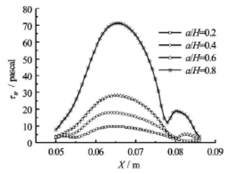
Fig.5 Effect of a/Hon wall shear stress at the bottom of cavity
From Fig.4 it can be seen that as a/Hincreases,the total pressure loss increases significantly. This is because whenaincreases, the flow resistance from the flow guide vane to the mainstream flow increases accordingly. Generally speaking, increasing the total pressure loss will reduce the aero-engine thrust[18], so the total pressure loss might not be too large.
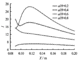
Fig.6 Effect of a/Hon turbulent intensity at central axis of the main combustion zone

Fig.7 Effect of b/Bon flow fields of center section
Figure 5 shows the effect of a/Hon the wall shear stress(τ)at the central lines of the bottom of the cavity. As a/Hincreases, the wall shear stress at the bottom of the cavity increases. This is due to the fact that the vortex in the cavity becomes larger, and the velocity gradient in the cavity increases accordingly as the increase ofa/H. Figure 6 shows the effect ofa/H on the turbulent intensity (I)at the central axis of the main combustion zone. It can be seen that the turbulent intensity increases with the increase of a/H, because the increase of the momentum in the main combustion zone will enhance the turbulent motion.
As above-mentioned, whena/H=0.4, a desirable dual-vortex structure will be formed with an acceptable pressure loss to achieve the stable combustion. Meanwhile the velocity in the main combustion zone is large enough, which can help to enhance the mixing of the fuel and the air. So the case ofa/H=0.4is selected to conduct the following study.
3.2 Effect ofb/Bon characteristics of TVC
Figure 7 shows the flow fields at the TVC center section withb/Bin the range from 0.2 to 0.8. It can be seen that a desirable dual-vortex structure forms in the cavity for eachb/B , which indicates that b/B has no obvious effect on the cavity flow structure. It should be noted that for b/B=0.8, the velocity in the main combustion zone increases significantly. It shows that whenb/Bincreases to a value large enough, it is favorable for enhancing the mixing of the fuel and the air.

Fig.8 Effect of b/Bon total pressure loss of outlet
Figure 8 presents the effect of b/Bon the total pressure loss of the outlet. It can be seen that asb/B increases, the total pressure loss increases. This is because whenb increases, the flow resistance from the flow guide vane in the cavity increases accordingly. It should be noted that for all values of b/B, the total pressure loss varies within a small range of 2.14% to 2.31%. A major implication of this phenomenon is thatb/Bhas little effect on the total pressure loss. To make best of the flow guide vane, with consideration of the total pressure loss and the mixing of the fuel with the air,b/B=0.4is adopted in practical applications.
Figure 9 shows the effect ofb/Bon the wall shear stress at central lines of the bottom of the cavity. Asb/Bincreases, the wall shear stress at the bottom of the cavity increases, which is due to the fact that the mass flow into the bottom of the cavity along theflow guide vane increases as b/Bincreases. However,the difference of the wall shear stress betweenb/B= 0.4 and 0.6 is not significant. Figure 10 shows the effect of b/Bon the turbulent intensity at the central axis of the main combustion zone. It can be seen that very little variation of the turbulent intensity can be observed whenb/B=0.2, 0.4 and 0.6. Further increasingb/Bto 0.8, the turbulent intensity becomes larger. This is because, as can be seen in Fig.7, when b/B=0.8, the velocity in the main combustion zone increases, and the increase of the momentum in the main combustion zone enhances the turbulent motion. But the turbulent intensity is slightly larger than those in the above cases. This may imply that there is no significant increase of the turbulent intensity in the main combustion zone with the increase ofb/B.

Fig.9 Effect of b/Bon wall shear stress at the bottom of cavity

Fig.10 Effect of b/Bon turbulent intensity of central axis in the main combustion zone
3.3 Effect of c/Lon characteristics of TVC
The flow fields in the cavity are strongly related withc/L. Hence, in order to have a better understanding of the effect ofc/Lon the cavity flow fields,the details of the cavity flow fields are shown in Fig.11.
As can be seen in Fig.11, a desirable dual-vortex structure forms in the cavity whenc/L=0.1. Increasingc/Lto 0.2, the dual-vortex is still in the cavity,while the area of the underside vortex reduces, because the effective length of the cavity reduces as c/L increases. Furthermore, there is a small vortex near the front wall of the cavity. When c/Lcontinues to increase to 0.3 and 0.4, the area of the underside vortex, as a pilot, becomes extremely small, which is not conducive to the ignition in the main combustion zone. The area of the upside vortex which enhances the mass and energy transport becomes smaller with the increases ofc/L. Moreover, the newly generated vortex near the front wall becomes large enough, which will break the stable combustion of the TVC.

Fig.11 Effect of c/L on flow fields of cavity center section

Fig.12 Effect of c/Lon wall shear stress at the bottom of cavity
Figure 12 shows the effect of c/Lon the wall shear stress at the central axis of the bottom of the cavity. Asc/Lincreases, the wall shear stress at the bottom of the cavity decreases. The reason is, as can be seen in Figure 11(b), that the underside vortex is away from the cavity bottom asc/Lincreases, which will reduce the wall shear stress at the cavity bottom.

Fig.13 Effect of c/Lon turbulent intensity of central axis of the main combustion zone
Figure 13 shows the effect of c/Lon the turbulent intensity at the central axis of the main combustion zone. Each curve can be divided into four parts. In the range of 0 to 0.025 m, the curves with different c/Lare overlapped. In the range of 0.025 m to 0.086 m, due to the effect of the flow guide vane, the curves begin to deviate from each other, and the turbulent intensity reduces with the increase ofc/L. As can be seen in Fig.11, with the decrease ofc/L, the velocity in the main combustion zone increases, which enhances the turbulent motion. For each curve in this range, the turbulent intensity firstly increases, then decreases and finally increases. In the range of 0.086 m to 0.14 m, the turbulent intensity increases with the increase ofc/L. For each curve in this range, the turbulent intensity decreases with the shift of the position. After 0.14 m, the turbulent intensity continues to decrease, while due to this position is at the downstream of the combustor, the increase ofc/Lhas no effect on the turbulent intensity in this range.

Fig.14 Effect of c/L on total pressure loss at outlet
Figure 14 shows the effect of c/Lon the total pressure loss at the outlet. As can be seen from Fig.14,the total pressure loss atc/L=0.1is a little larger than those in other cases. It indicates thatc/Lhas little effect on the total pressure loss. Based on the above discussion, whenc/L=0.1, the total pressure loss is relatively low, and a desirable dual-vortex structure forms in the cavity, which means that the optimal structural parameter isc/L=0.1.
3.4 Effect ofVmaon characteristics of TVC
From the above discussion, the optimal structural parameters of the flow guide vane area/H =0.4,b/B =0.4,c/L=0.1. In order to ascertain whether there will be a desirable dual-vortex structure in the cavity for various mainstream velocities(Vma), the effect ofVmaon flow fields of TVC is analyzed in detail.

Fig.15 Effect of Vmaon flow fields of center section
Figure 15 shows the effect of Vmaon the flow fields at the center section. As the mainstream velocityincreases, the velocity in the combustor increases accordingly, this is because the increase of Vmacan improve the momentum of the flow field. A desirable dual-vortex structure forms in the cavity for each Vma,with the same size and the same shape for all of these stable vortexes. It indicates that the dual-vortex structure is not related with the increase of Vma. With the optimal structural parameters of the flow guide vane,the flame is stable for all mainstream velocities.
3.5 Unsteady simulations
To have a better picture of the generation and the development of the vortex in the cavity, the unsteady simulation is conducted. The-6time step chosen for the unsteady simulation is 6×10 s. Figure 16 and Fig.17 show the instantaneous flow fields and the instantaneous vorticity contours at the center section of the TVC at time of 0.6 ms-3.0 ms.
From Fig.16, when t =0.6ms, because of the diversion effect of the flow guide vane, in a small portion of the mainstream along the cavity front-wall, a non-fully developed vortex is formed, meanwhile,another vortex forms behind the flow guide vane. This phenomenon can be expected intuitively as shown in Fig.17. There are two obvious places of high-vorticity near the flow guide vane when t =0.6ms. It indicates that two small vortexes are formed in these places.

Fig.17 Instantaneous vorticity contours at center section
The underside vortex grows larger, the upside vortex is squeezed by the underside vortex and the upside vortex moves to the right of the cavity. When t =1.2 msthe upside vortex is about to be transported to the outside of the cavity. With time progressing,the underside vortex becomes larger, and a new upside vortex appears near the flow guide vane. When t= 3.0 ms, the two vortexes are fully developed, gradually it assumes a desirable cavity dual-vortex structure while ensuring an extremely steady combustion. According to Fig,17, the variation of the vorticity and the movement of the vortex core demonstrate that the vortex expands to downstream of the combustor gradually, with breakdown and formation of vortexes. The vorticity of the dual-vortex increases during this time.
4. Conclusions
The cold flow characteristics of the TVC are investigated to show the effect of the structural parameters of the flow guide vane and the mainstream velocities on the TVC. Within the parameter range of this paper, the conclusions are as follow:
(1) As a/Hincreases, the velocity in the upper zone increases accordingly. Moreover, the total pressure loss, the wall shear stress at the bottom of the cavity and the turbulent intensity in the main combustion zone increase significantly.
(2)b/Bdoes not have a significant effect on the cavity flow structure and the total pressure loss at the outlet. Asb/Bincreases, the wall shear stress at the bottom of the cavity increases. No significant increase is observed of the turbulent intensity in the main combustion zone with the increase ofb/B.
(3) The increase of c/Lhas relatively little effect on the total pressure loss, and it is not conducive to the stable combustion. Asc/Lincreases, the wall shear stress at the bottom of the cavity decreases.
(4) Whena/H =0.4,b/B =0.4,c/L=0.1, a desirable dual-vortex structure can be formed with an acceptable pressure loss to achieve a stable combustion. So it is the optimal structural parameters of the flow guide vane.
(5) As the mainstream flow velocity increases,the velocity in the combustor increases. The dual-vortex structure is not related with the increase ofVma. With the optimal structural parameters of the flow guide vane, the flame is stable for all mainstream velocities.
(6) An unsteady simulation in the paper is carried out for the generation and the development of the vortex in the cavity. The underside vortex grows larger,the upside vortex is transported to the outside of the cavity with breakdown and formation of vortexes. Then a new vortex appears near the flow guide vane. Finally, the two vortexes are fully developed, with a desirable cavity dual-vortex structure.
References
[1] HSU K. Y., GOSS L. P. and ROQUEMORE W. M. Characteristics of a trapped-vortex combustor[J]. Jour- nal of Propulsion and Power, 1998, 14(1): 57-65.
[2] KATTA V. R., ROQUEMORE W. M. Numerical studies on trapped-vortex concepts for stable combustion[J]. Journal of Engineering for Gas Turbines and Power, 1998, 120(1): 60-68.
[3] ZHANG Rong-chun, FAN Wei-jun. Experimental study of entrainment phenomenon in a trapped vortex combustor[J]. Chinese Journal of Aeronautics, 2013, 26(1): 63-73.
[4] KULSHRESHTHA D. B., CHANNIWALA S. A. Trapped vortex combustion chamber: Design and experimental investigations using hydrogen as fuel[J]. Journal of the Institution of Engineers (India): Series C, 2014, 95(1): 69-75.
[5] SINGHAL A., RAVIKRISHNA R. Single cavity trapped vortex combustor dynamics-Part-1: Experiments[J]. International Journal of Spray and Combu- stion Dynamics, 2011, 3(1): 23-44.
[6] SINGHAL A., RAVIKRISHNA R. Single cavity trapped vortex combustor dynamics-Part-2: Simulations[J]. International Journal of Spray and Combustion Dy- namics, 2011, 3(1): 45-62.
[7] AGARWAL K. K., KRISHNA S. and RAVIKRISHNA R. V. Mixing enhancement in a compact trapped vortex combustor[J]. Combustion Science and Technology, 2013, 185(3): 363-378.
[8] CHEN S., CHUE R. S. M. and SCHLÜTER J. et al. Numerical investigation of a trapped vortex miniature ramjet combustor[J]. Journal of Propulsion and Power, 2015, 31(3): 872-882.
[9] GHENAI C., ZBEEB K. and JANAJREH I. Combustion of alternative fuels in vortex trapped combustor[J]. Energy Conversion and Management, 2013, 65: 819- 828.
[10] ROQUEMORE W. M., SHOUSE D. and BURRUS D. et al. Trapped vortex combustor concept for gas turbine engines[R]. AIAA paper 2001-0483, 2001.
[11] EZHIL KUMAR P. K., MISHRA D. P. Numerical simulation of cavity flow structure in an axisymmetric trapped vortex combustor[J]. Aerospace Science and Technology, 2012, 21(1): 16-23.
[12] MEYER T. R., BROWN M. S. and FONOV S. et al. Optical diagnostics and numerical characterization of a trapped-vortex combustor[R]. AIAA paper 2002-3863, 2002.
[13] STONE C., MENON S. Simulation of fuel-air mixing and combustion in a trapped vortex combustor[R]. AIAA paper 2000-0478, 2000.
[14] XING Fei, MENG Xiang-tai and LI Ji-bao et al. Elementary study on cool flow field of double vortex in cavity for flame stabilization[J]. Journal of Propulsion Tech- nology, 2008, 29(2): 135-138(in Chinese).
[15] ZHANG Tao, SONG Shuang-wen and FAN Wei-jun et al. Experimental study on lean-blow-out of double/fuellean trapped vortex combustor[J]. Journal of Aerospa- ce Power, 2011, 26(6): 1328-1333(in Chinese).
[16] FAN Wei-jun,YI Qi and YAN Ming et al. A study of double vortex structure in the trapped vortex combustor[J]. Proceedings of the Chinese Society for Ele- ctrical Engineering, 2006, 26(9): 66-70(in Chinese).
[17] AGARWAL K. K., RAVIKRISHNA R. V. Experimental and numerical studies in a compact trapped vortex combustor: Stability assessment and augmentation[J]. Combustion Science and Technology, 2011, 183(12): 1308-1327.
[18] HUANG Yong. Combustion and combustor[M]. Beijing, China: Buaa Press, 2009, 244(in Chinese).
10.1016/S1001-6058(15)60535-2
(April 1, 2014, Revised December 9, 2014)
* Project supported by the National Natural Science Foundation of China (Grant Nos. 51066006, 51266013), the Aeronautical Science Fund (Grant Nos. 2013ZB56002,2013ZB56004).
Biography: WANG Zhi-kai (1989-), Male, Master
ZENG Zhuo-xiong,E-mail: zengzhuoxiong@tsinghua.org.cn
猜你喜欢
杂志排行

水动力学研究与进展 B辑的其它文章
- Classification of flow regimes in gas-liquid horizontal Couette-Taylor flow using dimensionless criteria*
- MHD flow of a visco-elastic fluid through a porous medium between infinite parallel plates with time dependent suction*
- Polymer flow through water- and oil-wet porous media*
- Hydrodynamics and modeling of a ventilated supercavitating body in transition phase*
- Numerical analysis of the unsteady behavior of cloud cavitation around a hydrofoil based on an improved filter-based model*
- Thermal instability and heat transfer of viscoelastic fluids in bounded porous media with constant heat flux boundary*