Classification of flow regimes in gas-liquid horizontal Couette-Taylor flow using dimensionless criteria*
2015-11-25HUBACZRobert
HUBACZ Robert
Faculty of Chemical and Process Engineering, Warsaw University of Technology, Warsaw, Poland,E-mail: r.hubacz@ichip.pw.edu.pl
Classification of flow regimes in gas-liquid horizontal Couette-Taylor flow using dimensionless criteria*
HUBACZ Robert
Faculty of Chemical and Process Engineering, Warsaw University of Technology, Warsaw, Poland,E-mail: r.hubacz@ichip.pw.edu.pl
2015,27(5):773-781
In this paper, the flow patterns observed in horizontal Couette-Taylor flow (CTF) were correlated using dimensionless numbers. The analysis of the results showed that the structure of the flow was an outcome of interaction between fluid inertia related to axial and rotational flows and gravitation. Therefore, the flow structures were correlated using axial and angular Reynolds numbers, and Archimedes number for the given value of gas-to-liquid flow ratio. Finally, the correlation for the prediction of the transition to the flow regime observed at high rotational speeds was proposed. The comparison with experiments carried out in the vertical CTF from the literature showed that this correlation can also be useful in the case of vertical flow.
gas-liquid flow, Couette-Taylor flow (CTF), flow regime maps
Introduction
In Couette-Taylor flow (CTF) apparatus, fluid flows through an annular space between two concentric cylinders, with the inner cylinder rotating (rotor)and the outer one remaining stationary. The resulting flow is a superposition of axial Poiseuille and rotating Couette flows. The most interesting features of this flow are hydrodynamics instabilities in a form of Taylor vortices, which occur when the angular velocity of rotor(ω)exceeds certain critical value. Nevertheless, the structure of such flow depends on both axial and rotational velocities[1]. The research[2,3]on the mass transfer in gas-liquid horizontal CTF revealed that it is possible to obtain the high values of volumetric mass transfer coefficients and interfacial area in this type of apparatus, which are additionally combined with the relatively low values of rotor power input. Meanwhile, the examples of recently investigated practical applications of gas-liquid CTF are: production of algal biomass[4], crystallization[5]or CO2absorption (in order to reduce its emission to the atmosphere)[6].
Vertical gas-liquid Couette-Taylor flow has already been investigated by many research groups[7-13]. Most of these works were focused on a case without liquid axial flow imposed by e.g. an external pump[8-13]. In these cases, two-phase flow was generated in various ways: gas bubbles were drawn from the free surface at the top of apparatus as a result of sucking action of Taylor vortices in the liquid phase, gas bubbles were generated as a result of cavitation when pressure was reduced by rotor rotation (near the rotor),or gas was introduced through a porous body at the bottom of apparatus. Some of those papers were concerned with the interaction between gas bubble and Taylor vortices in the liquid phase[9,11-13]. The flow regimes of the co-current axial flow of gas-liquid mixture (water and air were continuously supplied into the apparatus at its bottom) in vertical CTF apparatus were identified only by Shiomi et al.[7]. The authors distinguish the following flow regimes: dispersed bubble flow(D), transitional flow between bubble and spiral flows (TDS), triple-spiral flow (3-S), double-spiral flow (2-S), single-spiral flow (1-S), transitional flow between spiral and ring flows(TSR), ring flow(R). Similar flow regimes were also identified for a vertical CTF apparatus without axial liquid flow (only gas was introduced continuously through a porous body at the bottom of apparatus)[12]. According to theflow regime maps[7,12], the transition between bubble flow and transitional flow, as well as the transition from transitional flow to spiral flows did not depend strongly on axial flows of either liquid or gas. Nevertheless, the transition to ring flow was significantly affected by axial flow. Although the proposed flow regime maps[7,12]provide interesting information about the occurrence of flow regimes in vertical CTF apparatus,their application is rather limited. They were constructed based on the experiments in which only one gasliquid system was used. Therefore, it was not possible to transform them into a more generalized form by using e.g. dimensionless criteria.
The horizontal gas-liquid CTF, in which liquid axial flow was caused by an external pump, was investigated by Hubacz and Wronski[14]. These investigations were carried out for gas-water systems or gas-glycerine aqueous solutions systems, with surface tension values ranging from 0.066 N/m to 0.072 N/m. The authors identified several flow structures including: stratified flow (ST), slug flow (SL),transition flow 1 (TR1), disturbed slug flow (DSL),transition regime 2 (TR2), periodic flow (PE), high rotational speed regime (HR). Despite some significant differences, HR regime flow can be roughly considered as the equivalent of spiral or ring flows observed in vertical flow. The authors also discovered that flow structure in the horizontal gas-liquid CTF can be correlated using the modified value of liquid mass flux and the power demand for rotor rotation. Consequently, the flow regime map was proposed. Nevertheless,further investigation[15], during which other liquids(diesel oil and silicone oil) were used, revealed the need for the revision of this approach. The necessity of a new flow regime map in a more generalized form can be also underlined by the fact that flow regimes in CTF apparatus with continuous axial flow of gasliquid mixture have not been studied by many research groups so far. The only known example of such investigation (outside my group) is the paper of Shiomi et al.[7], in which the flow in vertical CTF apparatus was studied. Nevertheless, CTF apparatus operating in a continuous mode is interesting from the viewpoint of its practical application.
The objective of this work was to search for the criteria in the form of dimensionless numbers for flow pattern prediction in a horizontal CTF apparatus. The analysis focused mostly on how flow regimes change with the increasing value of rotor rotation frequency. Therefore, the transitions to DSL, TR2 and HR, which depended mostly on the value of angular velocity at the rotor surface, were discussed in detail in the text.
1. Material and methods
Details of the experiments were described elsewhere[14]. The experimental apparatus consisted of a gas distributor, working zone made of a transparent Plexiglas tube (outer cylinder), and rotor (see Fig.1). Three different rotors with radii R1=0.055 m,0.048 m or 0.04 m and with the length of 0.45 m were used. Taking into account that the radius of the apparatus outer cylinder wasR2=0.03m, the values of the inner to outer cylinder radius ratio (η=R1/R2)were 0.92, 0.8 or 0.66, with the width of the gap between cylinders (d=R2-R1)equalling 0.0025, 0.006 or 0.01 m, respectively. During the experiments, rotor angular velocity ω ranged from 15 rad/s to 190 rad/s.

Fig.1 Sketch of experimental apparatus with different gas distribution systems
Liquid was continuously supplied into the apparatus using an external pump. Superficial velocity of the liquid phase, which is presented in Table 1, was defined as uL=QL/π(), where QLis the volumetric flow rate of the liquid at its inlet to the apparatus. The properties of liquids used during the experiments are shown in Table 1. Nitrogen or air was used as the gas phase. As in the case of the liquid, superficial velocity of the gas was defined as
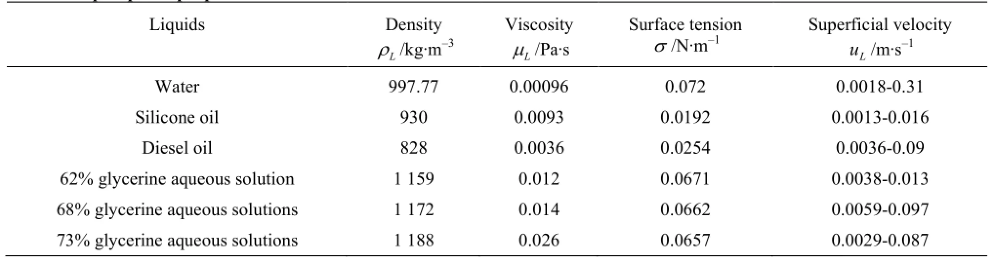
Table 1 Liquid phase properties

Table 2 Critical angular velocities at the transitions to DSL, TR2, HR

Fig.2 Examples of flow regimes
2. Results and discussion
2.1 Flow regimes in gas-liquid horizontal CTF
The horizontal gas-liquid CTF was investigated by Hubacz and Wronski[14]and Hubacz et al.[15]. The authors distinguished the following flow regimes which may be classified into 3 groups:
(1) Regimes observed at low rotational speeds,where gravity dominated the motion of the gas phase. Gas bubbles flew at the top of the apparatus, and in that part of it where buoyancy and drag forces acted in the opposite directions. The following regimes were observed (see also Table 2):
(a) stratified flow (ST)-layer of gas at the top of the apparatus,
(b) transition flow (TR1) between the stratified and slug flow-characterized by the formation of irregular elongated gas bubbles which could periodically change into a single gas layer at the top of the apparatus (Fig.2(a)),
(c) slug flow (SL)-at increasing axial flow rate most of the gas-phase flew in the form of a row of regular or sometimes irregular gas bubbles at the top of the apparatus (Fig.2(b)). The size of these bubbles was bigger than the gap between the cylinders.
(2) Flow regimes observed at transition rotational speeds where both buoyancy and rotor rotation effects could be seen:
(a) disturbed slug flow (DSL)-the row of gas bubbles, which was observed during SL, was disturbed(Fig.2(c)),
(b) transition regime (TR2) occurred between the flow regime of DSL and HR (see below), and it had features characteristic for both HR and DSL(Fig.2(d)),
(c) periodic flow (PE) took place when ST or SL flow regimes periodically changed into flow structures similar to TR2 or HR.
(3) Flow regimes observed at high rotational speeds: The high rotational (HR) speed regime could consist of either regular or irregular rings of bubbles,referred to as “ring flow”, or “irregular rings”(Figs.2(e), 2(f), 2(g), 2(h)). The influence of gravitation was not noticeable during HR.
The value of rotor angular velocity at the transition between flow regimes depended on gas-to-liquid flow ratio, apparatus geometry and properties of liquid phase. Nevertheless, it was noticed that the critical va-lues of angular velocity (ωc1,ωc2,ωc3), at which the transitions to DLS, TR2 or HR occurred, did not seem to be strongly affected by liquid axial flow, see examples in Fig.3. Therefore, the transition could be illustrated by the approximated critical values of angular velocity(ωc1,av,ωc2,av,ωc3,av)shown in Table 2. Those critical values ofωwere estimated using graphical method. For the given experimental conditions (defined by liquid properties, apparatus geometry and gasto-liquid flow ratio), flow regimes were plotted as a function of uLandω(see Fig.3), and the lines separating particular flow regimes were drawn. The transitions to DSL and to TR2 were usually less affected by uLthan transition to HR. Therefore, the values of ωc1,av,ωc2,avwere evaluated, a priori assuming that they did not depend on liquid axial velocity. On the contrary,ωc3usually slightly increased with the increasing value of uL. However, it could be approximated by a straight line. For the purpose of this paper,the value ofωc3,avwas calculated as an arithmetic mean ofωc3for the highest and lowest values of uLinvestigated at the given experimental condition (see Fig.3). The difference between ωc3,avand the values ofωc3was always lower than 14% (for the given experimental conditions).

Fig.3 Example of how flow regimes depended on rotor rotation and liquid axial flow (water-gas system).
2.2 Impact of operating parameters on the transitions between the flow regimes in horizontal CTF
It was noticed that the structure of gas-liquid horizontal CTF and the thresholds between flow regimes depended on apparatus size, gravitation, liquid and gas axial velocity, rotor angular velocity, liquid phase properties (density, viscosity). In addition to this, at the low values of rotor angular velocity the transitions between ST, TR1 and SL could probably also be affected by the properties of the interface between gas and liquid (surface tension). However, it could not be verified based on the present results. On the contrary, the borders between TR1 and DSL, DLS and TR2, or TR2 and HR (on which this paper was focused) did not seem to be significantly influenced by the values of the surface tension. It stemmed from the fact that during these experiments, inertia of fluid and gravitation dominated over the surface tension (0.8<Bo= gρd2/σ<17,We=(ωR)2dρ/σ>5.9). The di-L 1L mensional analysis suggested that the critical angular velocities at transitions between those flow regimes could be correlated using the following dimensionless parameters: gas-to-liquid flow ratio, angular Reynolds number(Rerot=ωR1dρL/µL), axial Reynolds number(Reax=uLdρL/µL), and Archimedes number(Ar= gd3ρ2/µ2). The Archimedes number could be interpreted as a ratio of buoyancy and viscous force. Besides angular Reynolds number, Froude number(Fr=ω2R/g)was also considered as the crite-1 rion for the prediction of changes in flow patterns in two-phase CTF with the increasing rotor rotation. Further analysis showed, however, that the satisfactory correlation of the experimental results was obtained only when angular Reynolds number was used for this purpose. Froude number might have been a better criterion if gravitation effects had become negligible at relatively low values ofω, i.e., before the formation of Taylor vortices in the liquid phase (e.g., in the case of more viscous fluids). Nevertheless, for the systems investigated here, the formation of Taylor vortices probably began before the transition to DSL. This statement is supported by the low value of angular Reynolds number at which Taylor vortex flow occurs in the case of single-phase liquid systems: e.g., 100-170 for η=0.85and Rebetween 0 and 40[1]. ax Moreover, the observed specific segregation of bubbles (in the form of rings) also suggested the importance of Taylor vortices for the formation of the flow patterns in two-phase CTF. Therefore, it was decided to usedRerotinstead ofFrfor the classification of the flow patterns in gas-liquid CTF.
In Figs.4-6, the critical values of angular Reynolds number(Rerot,c1,av,Rerot,c2,av,Rerot,c3,av)are shown as functions of the Archimedes number. The values of Reynolds numbers were calculated using the values ofωc1,av,ωc2,avand ωc3,avfrom Table 2. It can be seen that the critical values of angular Reynolds number seem to be independent from apparatus geometry and only slightly affected b y param eter β(especially Rerot,c2,avand Rerot,c3,av).Itwasalsonoticed form Figs.4-6 that the dependence of Rerot,c1,av,Rerot,c2,avand Rerot,c3,avon the Archimedes number changed its character atAr≈1.4×10⁵. It can be probably explained by the transition from laminar to turbulent flow in the liquid phase. During these experiments forAr>1.4×10⁵, the values of Rerot,c1,av,Rerot,c2,avand Rerot,c3,avexceeded 2 000, while in single phase CTF the turbulent character of flow was observed for approximatelyRerot>1000in the case of η=0.85[1], or Rerot>1411for η=0.62[17]. Furthermore, it is worth underlining that during these experiments0.7<Reax<51for Ar<1.4×10⁵and 17<Reax<921for Ar>1.4×10⁵.

Fig.4 Averaged critical values of angular Reynolds number at the transition to DSL

Fig.5 Averaged critical values of angular Reynolds number at the transition to TR2

Fig.6 Averaged critical values of angular Reynolds number at the transition to HR

Fig.7 Comparison of the critical value of angular Reynolds number at the transition to HR with the correlation Eq.(1)(line). In this figure there are shown experimental values of Rerot,c3obtained for the highest and the lowest values ofReaxstudied at the given experimental conditions. The value of the coefficient of determination wasR2= 0.966 for Ar<1.4×10⁵and R2=0.976for Ar>1.4×10⁵

As it was mentioned above, the impact of liquid axial flow on the transitions to DSL and TR2 was rather small, hence it was difficult to estimate how the value of uLinfluenced the values of ωc1and ωc2. On the contrary, the value of ωc3slightly increased with the increasing value ofuL. The dimensional analysis suggested that the transition to HR could be approximated using the following correlation where A =32,b =0.25,c =0.39,d =0.051for Ar<1.4×10⁵and A =23,b =0.13,c =0.45,d =0.037for Ar>1.4×10⁵, while critical Reynolds number was defined asRerot,c3=ωc3R1dρL/µLThe comparison of the experiments with this correlation is shown in Fig.7. The transition to HR was not strongly affected by axial flow of liquid phase. Nevertheless,these results seemed to indicate that such influence could be more visible beyond the range of liquid axial Reynolds number investigated here. In addition to this,the value of ωc3seemed to be affected more strongly byβanduLfor Ar<1.4×10⁵, for which the transition to HR occurred at the lower value of angularReynolds number than for Ar>1.4×10⁵.

Fig.8 Flow regime map for β=0.125

Fig.9 Flow regime map for β=0.25For Ar=1.07×10⁷and Reax>500, PE was observed as a transitional regime between DSL and TR2, which was not show in the figure
2.3 Flow regimes maps
On the basis of these considerations, it was noticed that the thresholds between the flow regimes in horizontal gas-liquid CTF could be correlated using angular and axial Reynolds numbers, Archimedes number and gas-to-liquid flow ratio. The flow regime maps for a given value ofβare shown in Figs.8-10. In order to prepare these figures, it was assumed that transitions to DLS, TR2, and HR did not depend on the axial flow. Moreover, it was assumed that the transitions between TR1 and SL, between PE and DSL or between PE and TR2 occurred at certain values of axial Reynolds number, while the impact of rotor rotation on the borders between those regimes was neglected in the figures. Despite these simplifications, the flow regime maps (shown in these figures) could provide some interesting information about the occurrence of these regimes.
As can be seen in Figs.8-10, the increase in the value ofAr moved the thresholds between the flow regimes towards the higher values of angular and axial Reynolds numbers. It meant that when the effect of buoyancy grew, higher values of liquid axial velocity or higher rotor rotation frequency were needed to overcome that effect. Consequently, the occurrence of ST, TR1 or PE was shifted towards lower values of ReaxwhenArdecreased. For some investigated gasliquid systems (characterized by rather low value of Ar), the transitions to these flow regimes probably took place at the lower value ofReaxthan it was studied. It explained why ST, TR1 or PE could be seen only during experiments with liquids of which Archimedes number had sufficiently high value.
As it can be seen in the Figs.8-10, ST was only observed forβ=0.125. In addition, the increase in βcaused the reduction in the size of the region where TR1 was observed. It can be explained by the growth in gas-liquid mixture axial flow after the increase in the value ofβ, which shifted the transition ST-TR1 and the transition TR1-SL towards the lower values of Reax. Such an impact ofβon the threshold between the flow regimes was noticed when gravitation dominated in the flow (low rotational speeds). On the contrary, at transition and high rotational speeds, the fact that the increase inβcaused the growth in the importance of gravitation in comparison to fluid inertia became more important. Therefore, the growth inβ caused the enlargement of the region where PE was observed (transitions to DSL and TR2 at higher values of Reax), and the shift of transitions to DSL, TR2 or HR toward higher values of angular Reynolds number. A similar effect was already reported by Murai et al.[12]in the case of vertical gas-liquid CTF. In addition to this, it was noticed that the impact of gas-to-liquidflow ratio on the transitions to DSL or to TR2 was stronger than in the case of the transition to HR. Consequently, the range of the value ofωin which DLS,TR2 and PE were observed shrank with the increasing value ofβ(see Figs.8-10). The flow structure at the transition to HR was less susceptible to the influence of gas flow than the transitions to DSL or to TR2, because ωc3>ωc2>ωc1, which denoted a stronger flow structure (i.e., Taylor vortices) in the liquid phase.

Fig.10 Flow regime map for β=0.5. For Ar=1.07×10⁷PE was observed as a transitional regime between DSL and TR2, which was not show in the figure
2.4 Comparison between horizontal and vertical flow
The vertical gas-liquid CTF with the axial flow of both phases was studied by Shiomi et al.[7]. However, their results were obtained only for an airwater system with the gas-to-liquid ratio between 0.05 and 0.92. The radii of the rotor and outer cylinder used in the experiments were 0.09 m and 0.1 m, respectively. It means that for their system the value of Archimedes number was 9.81×10⁶, and the values of axial Reynolds number were between 700 and 2 675.
The authors[7]discovered that as the rotor rotation velocity increased, the following flow regimes successively occurred: dispersed bubble flow(D), transitional flow between bubble and spiral flows (TDS),triple-spiral flow (3-S), double-spiral flow (2-S), single-spiral flow (1-S), transitional flow between spiral and ring flows (TSR), ring flow (R). In the case of vertical flow, the borders between the regimes observed at high rotational speeds were affected by both liquid and gas axial flows: at the higher axial flow, the transitions between flow regimes occurred at the higher rotor rotation. On the contrary, the borders between the regimes observed at low or transition rotational speeds were independent from the liquid axial flow and gas-to-liquid flow ratio. Consequently, the transition betweenD and TDSoccurred at Rerot= 16 336, while the transition between TDSand spiral flows occurred at Rerot=32673for all investigated values of Reaxandβ.
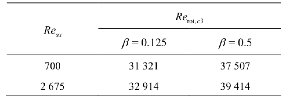
Table 3 The value of Rerot,c3calculated using Eq.(1)
The flow regimes (Dand TDS) observed at low or transition rotational speeds were completely different from the regimes observed in horizontal flow. But when the speed increased, the differences between the horizontal and vertical flows became smaller, hence HR flow (horizontal CTF) can be considered as a rough equivalent of spiral or ring flows (vertical CTF). The values of Rerot,c3calculated using Eq.(1) for the flo[7]conditions like in the experiments of Shomi et al. are shown in Table 3. The significant impact of βon the value of Rerot,c3can be related to the fact that gas hold-up is higher in horizontal than vertical CTF at least at relatively low rotational speeds. Although the values of Rerot,c3in Table 3 are affected by liquid and gas axial flows, the difference between them and the value of Rerotat the border between TDSand spiral flows (see above) is less than 17.1%. Moreover, Eq.(1) predicted the increase in Rerot,c3of less than 5% when the value of Reaxincreased 3 times. Therefore, it can be stated that the Eq.(1) can also be used in the case of vertical CTF for the rough estimation when Taylor vortex pattern becomes dominant in the flow at least for 0.125<β<0.5.
3. Conclusion
The dimensionless number for the correlation of the flow structure in horizontal gas-liquid CTF was chosen. It allowed to elaborate the criteria for the critical values of angular Reynolds number at the borderbetween flow regimes. In addition to this, the flow regimes maps were proposed. The criterion for Rerot,c3,which denotes the critical value ofRerotat the transition to HR, was presented in the form of an equation Eq.(1). Finally, it was noticed that this equation could be probably used also for the prediction of the transition to spiral flow regimes in vertical CTF. It is worth remembering, however, that the approach proposed herein represents the case in which Taylor vortices in the flow occur before the effects of gravitation become negligible. Similarly, different criteria for flow regimes classification may be needed if surface phenomena dominate over gravitation effects in the studied system (e.g., at reduced gravitation).
References
[1] LUEPTOW R. M., DOCTER A. and MIN K. Stability of axial flow in an annulus with a rotating inner cylinder[J]. Physical of Fluids A Fluid Dynamics, 1992, 4(11): 2446-2455.
[2] WRONSKI S., DLUSKA E. and HUBACZ R. et al. Mass transfer in gas-liquid Couette-Taylor flow in membrane reactor[J]. Chemical Engineering Science, 1999, 54(1): 2963-2967.
[3] WRONSKI S., HUBACZ R. and RYSZCZUK T.Interfacial area in a reactor with helicoidal flow for the two-phase gas-liquid system[J]. Chemical Engineering Journal, 2005, 105(3): 71-79.
[4] KONG B., SHARKS J. V. and VIGIL R. D. Enhanced algal growth rate in a Taylor vortex reactor[J].Biotechnology and Bioengineering, 2013, 110(8): 2140-2149.
[5]KIM W.-S.Application of Taylor vortex to crystallization[J].Journal of Chemical Engineering of Japan, 2014, 47(2): 115-123.
[6] PINEDA I. T., CHOI C. K. and KANG Y. T. CO2gas absorption by CH3OH based nanofluids in an annular contactor at low rotational speeds[J].International Journal of Greenhouse Gas Control, 2014, 23: 105-112.
[7] SHIOMI Y., KUTRUNA H. and AKAGAWA K. et al. Two-phase flown in an annulus with a rotating inner cylinder (flow pattern in bubbly flow region)[J]. Nuclear Engineering and Design, 1993, 141: 27-34.
[8] ATKHEN K., FONTAINE J. and WESFREID J.-E. Highly turbulent Couette-Taylor bubbly flow patterns[J]. Journal of Fluid Mechanics, 2000, 422: 55-68.
[9] DJERIDI H., GABILLET C. and BILLARD J. Y. Twophase Couette-Taylor flow: Arrangement of the dispersed phase and effects on the flow structures[J]. Physics of Fluids, 2004, 16(1): 128-139.
[10] MEHEL A., GABILET C. and DJERIDI H. Analysis of the flow pattern modification in a bubbly Couette-Taylor flow[J]. Physics of Fluids, 2007, 19(11): 118101.
[11] CLIMENT E., SIMONET M. and MAGNAUDET J. Preferential accumulation of bubbles in Couette-Taylor flow patterns[J]. Physics of Fluids, 2007, 19(8): 083301.
[12] MURAI Y., OIWA H. and TAKEDA Y. Frictional drag reduction in bubbly Couette-Taylor flow[J]. Physics of Fluids, 2008, 20(3): 034101.
[13] YOSHIDA K., TASAKA Y. and MURAI Y. et al. Mode transition in bubbly Taylor-Couette flow measured by PTV[J]. Journal of Physical: Conference Series, 2009, 147: 012013.
[14] HUBACZ R., WROŃSKI S. Horizontal Couette-Taylor flow in a two-phase gas-liquid system: Flow patterns[J]. Experimental Thermal and Fluid Science, 2004,28(5): 457-466.
[15] HUBACZ R., SUJKA K. and WRONSKI S. Flow structure in the gas-liquid horizontal Couette-Taylor flow[C]. The 7th International Symposium on Transport Phenomena. Toyama, Japan, 2006.
[16] SUJKA K. Investigation of hydrodynamics of gas-liquid Couette-Taylor flow[D] Master Thesis, Warsaw, Poland: Warsaw University of Technology, 2005.
[17] KATAOKA K. Taylor vortices and instabilites in circular Couette flows (CHEREMISINOFF N. P. Eds. Encyclopedia of fluid mechanics)[M]. Houston, USA: Golf Publishing Company, 1986, 236-274.
10.1016/S1001-6058(15)60539-X
(September 11, 2014, Revised December 2, 2014)
* Biography: HUBACZ Robert (1972-), Male, Ph. D.,Assistant Professor
杂志排行

水动力学研究与进展 B辑的其它文章
- Thermal instability and heat transfer of viscoelastic fluids in bounded porous media with constant heat flux boundary*
- Numerical analysis of the unsteady behavior of cloud cavitation around a hydrofoil based on an improved filter-based model*
- Combined effect of Reynolds and Grashof numbers on mixed convection in a lid-driven T-shaped cavity filled with water-Al2O3nanofluid*
- Hydrodynamics and modeling of a ventilated supercavitating body in transition phase*
- Polymer flow through water- and oil-wet porous media*
- MHD flow of a visco-elastic fluid through a porous medium between infinite parallel plates with time dependent suction*