Experimental investigation of the optimization of stilling basin with shallowwater cushion used for low Froude number energy dissipation*
2015-11-24LILianxia李连侠LIAOHuasheng廖华胜LIUDa刘达JIANGShengyin蒋胜银
LI Lian-xia (李连侠), LIAO Hua-sheng (廖华胜), LIU Da (刘达), JIANG Sheng-yin (蒋胜银)
1. State Key Laboratory of Hydraulics and Mountain River Engineering, Sichuan University, Chengdu 610065,China, E-mail: lianxiali@scu.edu.cn
2. Guangdong Research Institute of Water Resources and Hydropower, Guangzhou 510635, China
3. Chengdu Municipal Engineering Design and Research Institute, Chengdu 610023, China
Experimental investigation of the optimization of stilling basin with shallowwater cushion used for low Froude number energy dissipation*
LI Lian-xia (李连侠)1, LIAO Hua-sheng (廖华胜)1, LIU Da (刘达)2, JIANG Sheng-yin (蒋胜银)3
1. State Key Laboratory of Hydraulics and Mountain River Engineering, Sichuan University, Chengdu 610065,China, E-mail: lianxiali@scu.edu.cn
2. Guangdong Research Institute of Water Resources and Hydropower, Guangzhou 510635, China
3. Chengdu Municipal Engineering Design and Research Institute, Chengdu 610023, China
Energy dissipations induced by the hydraulic jump and the trajectory jet are the most widely known as the two dissipation modes at the downstream of flood discharging structures, which are often considered quite different even contradictory. However,such two energy dissipators can be used jointly and harmonically. In this paper, a new type of stilling basin with a shallow-water cushion and a triangular bottom deflector is proposed based on two different scale physical model tests of the flood discharging tunnel No.2 of Luding hydropower project. The experimental results show that the flow regime of the hydraulic jump in the presented stilling basin with bottom deflector enjoys a good and stable performance within a large range of flow rates and the energy dissipation rate is considerably high as compared to the conventional stilling basin even at a low Froude number. The results also indicate that the stilling basin with triangular bottom deflector has a better performance in improving the potential cavitation erosion according to the analysis of the pressure and the cavitation number compared to the trapezoidal one. The proposed new type of shallow-cushion stilling basin with a shallow-water cushion can be applied in similar energy dissipation projects with low Froude number and large range of flow rates.
stilling basin, shallow-water cushion, energy dissipation, low Froude number, bottom deflector
Introduction
Currently the hydraulic jump is the most widely measure taken to dissipate the excessive energy of the rushing flow out of the discharging flood structure such as the flood discharging tunnel, the spillways,and the sluice gates, and it is considered as safe and free from atomization[1,2]. The stilling basins are generally designed on the basis of the inflow Froude numberFr and the model experimental results. The Froude number for the stilling basin is defined as Fr=V/(gy )1/2whereV is the velocity of the incoming flow to the stilling basin,g is the acceleration of gravity andy is the depth of the supercritical flow. However, it is shown that a hydraulic jump stilling basin is not an efficient energy dissipator at low Froude numbers, that is, the efficiency of a hydraulic jump basin is less than 20 percent for Fr<2.7[3]. In addition, for the projects with high water head and large discharge, it becomes an important issue that the structure may be potentially damaged by the violent fluctuation of the hydrodynamic pressure and the high velocity near the bottom of the stilling basin. Therefore, the modification has been continuously made on the traditional stilling basin[4-7]. Many new types of stilling basin were proposed with auxiliary dissipators or modified basin shapes[8-18], among which a relatively new stilling basin with shallow-water cushion(SBSWC)[11,12]with an abrupt drop and a tail sill located at the inlet and outlet of the stilling basin enjoys a good performance in reducing the bottom velocity and improving the pressure distribution of the stillingbasin walls due to the effects of absorption and buffer action of the water cushion, and it can provide a good and complete hydraulic jump when the depth of tailwater is inadequate for the traditional stilling basin[7,8].
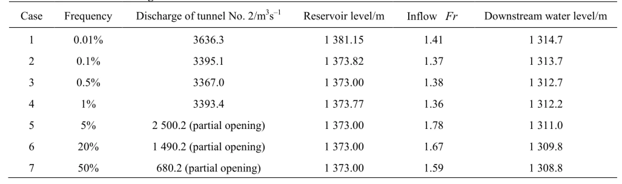
Table 1 Test cases in the integrated model
The Luding Hydropower Project, with an installed capacity of 920 MW, is a large-scale hydropower station with rockfilled-dam in the Dadu River, upstream of the Yangtze River, China. The sluicing system contains 3 flood discharging tunnels (one on the left bank, two on the right bank). The energy dissipation downstream of the dam becomes one of the most important issues because of the deep overburden river bed and the potential landslide body near the left bank of the downstream.
This paper is focused on the energy dissipator at low Froude number (less than 2.0 in all running cases)of the flood discharging tunnel No.2 on the right bank whose spectacular w3ater head and discharge are about 74 m and 3 393.4 m/s in a running case of the design flood with the occurrence frequency of P=1%. The tunnel is an open channel with a U-shape cross section of 13 m (width) by 9m (height) and a short inlet section, with an inclined slope of 0.01123 and a total length of 1 353.35 m. Due to the geologic exposure during the excavation, the outlet of the tunnel is expected to shift about 97m towards downstream, whereas,some parts of the original designed stilling basin will be located on the deep overburden foundation (river bed). If it is let to be shifted without modification,some potential safety issue will arise for the dissipator itself and the stability of the potential landslide body on the opposite bank will be threatened. Therefore, a series of experimental tests based on two different scales are conducted to optimize the energy dissipator to guarantee the safety and the stability with a high energy dissipation rate and a good flow pattern. In order to obtain an optimal dissipator for the project,under the condition of different flood discharges, the measurements of the regime of the hydraulic jump, the water surface, the velocity, as well as the static and fluctuating pressures are carried out and the results are analyzed in the physical models.

Fig.1 The integrated physical model system
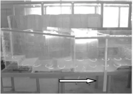
Fig.2 The local model experiment system
1. Model design and test facility
An integrated model system is established based on the geometric similarity (scale 1:70), including the reservoir, the dam, 3 flood discharging tunnels and the downstream river reach, as shown in Fig.1. The energy dissipator of the flood discharging tunnel is tested in seven running cases with different discharges and conditions as listed in Table 1. And a larger scale(1:40) local model of the stilling basin of tunnel 2 is built to determine the detailed velocity and pressure distributions in the stilling basin, as shown in Fig.2.Two typical running cases are selected to test the model, i.e.,P =1%and P =5%as Cases 4 and 5 listed in Table 1. It is seen from Table 1 that the Froude numbers(Fr )for the incident flow are very low (i.e., less than 2.0) in all running cases.
The velocity is measured by means of the Pitot tube, the propeller flow velocimetry (PFV), and the static and fluctuating pressures are measured by the piezometric tubes and the pressure sensors at 131 locations on the bottom and side walls of the stilling basin; and the flow rate is controlled by a sharp-crested rectangular weir.
2. Mathematical model and numerical methods
Due to the limitation of physical measurements, a numerical simulation[10]using a 3-D RNG k-εturbulence model is carried out to obtain the details of the velocity field in the stilling basin and using the VOF method to capture the free surface.
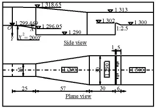
Fig.3 The ordinary stilling basin with shallow-water cushion
3. Results
3.1Stilling basin with shallow-water cushion
Based on the preliminary experiments, an ordinary stilling basin with a shallow-water cushion (see Fig.3) modified from that in Ref.[11] is built and tested firstly under the design flood conditions: the occurrence frequency of P =0.01%and P=0.1%(Cases 1 and 2 in Table 1).
The flow regime (see Fig.4) is very good with a strong agitation taking place in the whole stilling basin, with a low exit and bottom velocity (see Fig.5, X is the distance from the dam andZ stands for elevation)[12]and a high energy dissipation rate. However, the hydraulic jump comes from over-submergence that makes the submerging front moving into the outlet of the tunnel in the running Case 1. Over-submergence may potentially cause a serious problem of blocking the tunnel, which is not permitted in practical engineering due to the insufficient height of the tunnel. Therefore, appropriate measures must be taken to reduce the submergence near the tunnel outlet to ensure the whole surface roller is housed within the stilling basin.
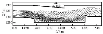
Fig.5 Numerical simulation velocity structure and water surface of running Case 1
3.2Stilling basin with shallow-water cushion and trapezoidal bottom deflector
To avoid the front of the surface roller moving into the tunnel, based on the previous test results,some auxiliary devices are introduced to push the front to the downstream. Firstly, the bottom elevations of the just inlet and outlet of the stilling pool are raised by 3 m locally to reduce the depth of the water cushion there so that the submerged effect near the tunnel outlet can be reduced. Then a trapezoidal shaped bottom deflector is set at the middle of the stilling basin to divide the basin into two parts and adjust the direction of the bounced mainstream towards the downstream by the deflector to ensure a good and sta-ble performance of the stilling basin within a large range of flow rates. It should be noted that these modifications are based on the observations of flow regimes under different running cases. The details of dimensions of the modified stilling basin are shown in Fig.6.

Fig.4 Flow regime in the stilling basin

Fig.6 The stilling basin with shallow-water cushion and trapezoidal bottom deflector
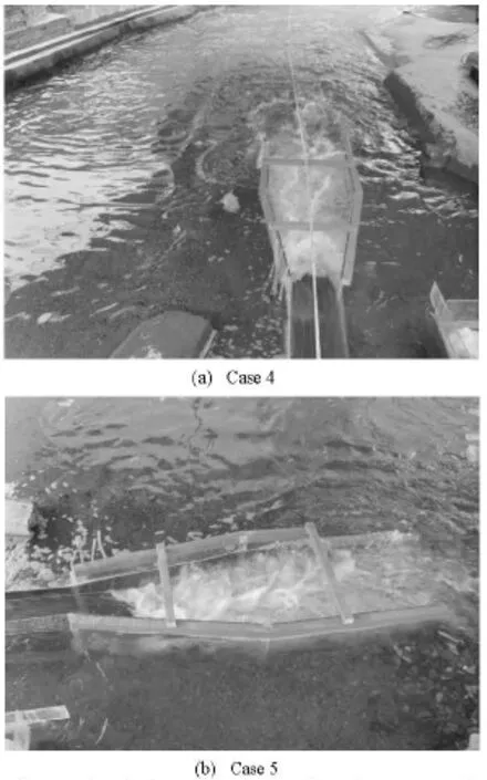
Fig.7 The flow regime in the stilling basin
The experimental results show that a good and stable flow regime of hydraulic jump in the modified stilling basin is achieved and the hydraulic jump is completely housed within the stilling basin and the submerged front is now about 10 m away from the tunnel outlet in all running cases (Fig.7), as a result of the modification mentioned above. In the case of low discharge, the first basin plays a primary role and the two basins contribute to the energy dissipation jointly in the case of large discharge, therefore, the new stilling basin performs well with a large variation of discharge. In the running case 4, the velocity of the inflow of 23 m/s is effectively reduced to less than 8.5 m/s at the end of the basin, and the water surface profile is quite smooth with a small drop around the end of the jump. The velocity continues to decrease in the downstream of the stilling basins and is brought down to less than 3 m/s near the potential landslide body site (Fig.8,Lis the distance from the outlet of the basin andYthe distance from basin axis), the river bed topography observation (Fig.9) shows that no severe scour erosion is caused and no bedrock exposes. The downstream and the potential landslide bodies are protected from the scouring damage due to the considerably high energy dissipation rate of the new stilling basin. It should be noted that the velocity in figure 8 is measured in the case of P=1%, in which both discharge tunnels 1 and 2 run jointly.
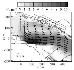
Fig.8 Velocity field in the downstream of Case 4
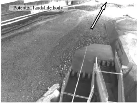
Fig.9 Scour topography in the downstream of Case 4
The stilling basin with a shallow-water cushion and a trapezoidal bottom deflector seems ideal for this project in view of its good behavior in the regimes, thevelocity and the high energy dissipation rate, however the safety of the stilling basin itself, especially, of the bottom deflector, including the cavitation and the fluctuation pressure, should be investigated in a larger scale model, which will be described in the following sections.
3.3Shallow-cushion stilling basin with a trapezoidal bottom deflector
3.3.1Flow regime and water surface
The flow regime and the water surface profile are almost identical to those in the integrated model,which are very satisfactory as well (Fig.10).
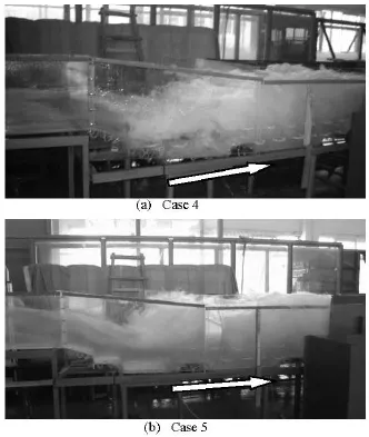
Fig.10 Flow regimes in stilling basin with shallow-water cushion and trapezoidal bottom deflector
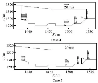
Fig.11 Velocity distributions in stilling basin with shallowwater cushion and trapezoidal bottom deflector at typical profiles
3.3.2Velocity and energy dissipation
The velocity distributions at typical profile locations show that the main flow is vertically located at the middle of the shallow-water cushion and the bottom velocity is the lowest due to the water cushion, as can be seen from Fig.11 and consistent with those results obtained from the references[10,11]. In the case of P=1%, the high velocity of larger than 21 m/s at the inlet location is reduced to about 12 m/s after the deflector and it is larger than 7.5 m/s at the end of the stilling basin and the other case shows similar patterns,which implies a high energy dissipation rate of the presented dissipator.
3.3.3Pressure and cavitation
The static pressure has a uniform distribution in the transverse direction and varies along the longitudinal direction. In the case of P=1%, a negative pressure less than -7 m is seen in the area near the inlet and a negative pressure less than -3.8 m is seen at the start point of the platform of the defector. The maximum positive pressure is found in the impinging zone near the start point of the slope of the deflector with a value of 35 m.The square root of the fluctuation pressure on the sidewalls is relatively small with the maximum of 5.3 m, compared with 10.3 m in the bottom at the end sill.
From the formula for the cavitaion number, we have
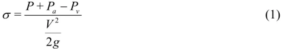
in whichσ,PandV are the cavitation number,the relative pressure and the velocity at the interested location, respectively,Paand Pvthe local atmosphere pressure and the vapor pressure, respectively. Generally speaking, the cavitation occurs at the locatuin where the cavitation number is less than the incipient cavitation number of the structure, which can hardly be obtained without complicated tests of pressure reduction and is often relatively conservatively taken as 0.3 based on the experience for the convenient practice. Based on Eq.(1), the minimum cavitation number found is about 0.22, which means that the potential cavitaion damage in the high negative pressure aera is most likely.
3.4Stilling basin with shallow-water cushion with a triangular bottom deflector
Though the shallow-cushion stilling basin with a trapezoidal bottom deflector performs quite well in many aspects, some optimization is essential to mitigate or eliminate the negative pressures at the inclined inlet of the basin and the platform of the bottom of thetrapezoidal deflector. Therefore, a sudden expansion of 1 m on both sides is made to the outlet of the tunnel as a side wall aerator to increase the aeration intensity,meanwhile, the shape of the bottom deflector is changed from a trapezoid to a triangle (side view) to have a more smooth flow pattern. The detail of the dimensions of the new stilling basin with a triangular bottom deflector is depicted in Fig.12.
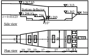
Fig.12 Stilling basin with shallow-water cushion and triangular bottom deflector
To compare with the scheme before the modification, the new stilling basin with a triangular bottom deflector is tested under the same conditions of the running Cases 4 and 5.
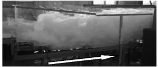
Fig.13 Flow regime of hydraulic jump
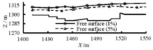
Fig.14 Water surface profiles
3.4.1Flow regime and water surface
The turbulent flow regime of the hydraulic jump is even better and more stable after the modification and the water profile connection with the river level downstream becomes smoother as shown in Figs.13 and 14. With the sudden expansion, the rushing flow does not diffuse to the side walls immediately after flowing out of the tunnel, and two horizontal inverse flows emerge in the separated zones of the transition section symmetrically. The main flow is divided into two parts after hitting the bottom reflector: one bounces to the upstream and collapses with the main flow and the rest major flow is reflected to the downstream along the reflector to form the surface roller, the other part is submerged and forms another small backflow near the downstream of the bottom deflector by the great barrier of the water body in the second basin. As mentioned above, the forms of the basin inlet and outlet ensure the hydraulic jump housed in the basin and prevent the flow from entering into the tunnel. More importantly, the two sub basins separated by the bottom deflector make it flexible to suit different flow rates. Accordingly, the stable hydraulic jump is made of many reverse or back flows caused by the sudden expansion, the abrupt drops and the bottom deflector,which contribute to the high efficiency of the energy dissipation.
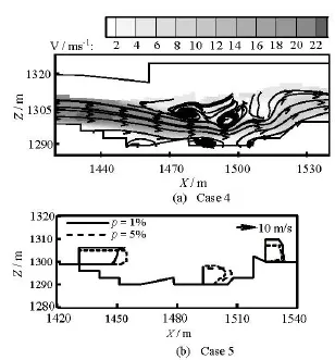
Fig.15 Velocity field and streamlines and vertical velocity distribution
3.4.2Velocity and energy dissipation
Three large eddies can be seen obviously from the flow field shown in Fig.15(a), as calculated in Ref.[10] and by experimental observations, two of them are located at the upper parts of the upstream and downstream of the triangular bottom deflector, respectively, and the third one is just in the downstream of the deflector close to the bottom, which ensures the high turbulent flow and the high energy dissipation rate in the stilling basin. Such flow structure has a very different pattern from that in the ordinary stilling basin, where only one upper larger eddy is found. The velocity decreases rapidly in the stilling basin and about half kinetic energy is dissipated through the triangular bottom deflector (see Fig.15(b)). For example, under the condition of the design flood (P =1%), thevelocity is reduced by almost half from 22.9 m/s to 11.2 m/s through the defector and to around 8.8m/s at the end of the stilling basin and from 21.1 m/s to 9.5 m/s to 7.9 m/s in the case of P=5%. In addition,the bottom velocity is less than 12 m/s, which is much further away from the maximum one as always happens in a traditional stilling basin, therefore, the bottom of the stilling basin can be protected effectively by the shallow water cushion.
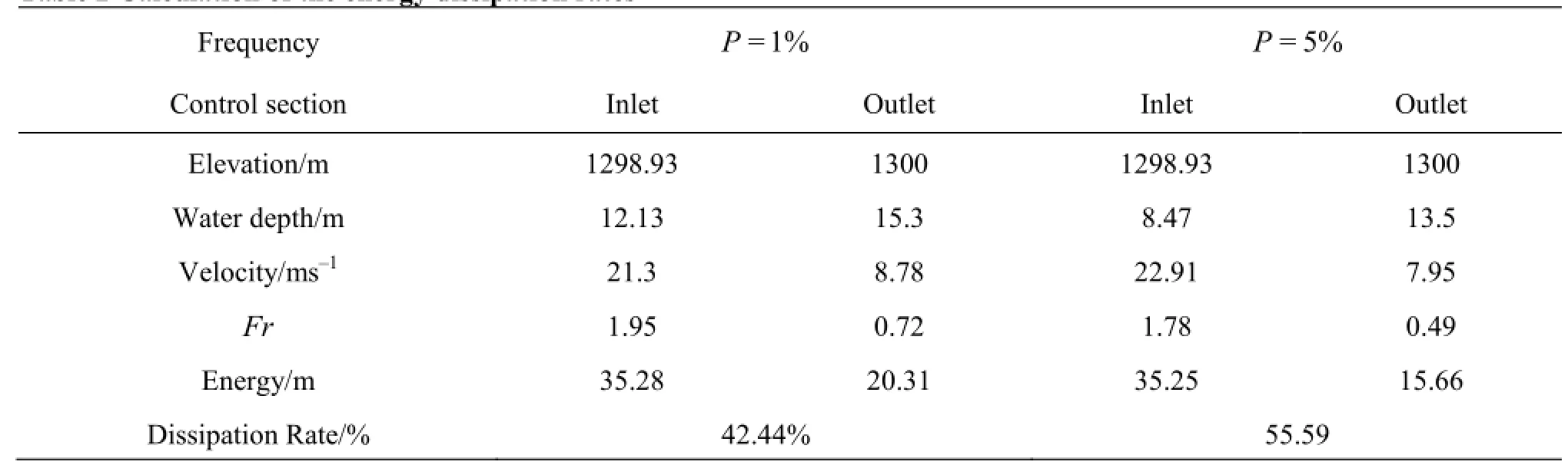
Table 2 Calculation of the energy dissipation rates
The excessive energy loss efficiency of the stilling basin with a shallow-water cushion and a triangular deflector might be better than twice of that of the traditional stilling basin. For example, at the low inflow Froude number of 1.95, the energy dissipation rate for the latter is only 20%, while the former reaches 42% in case ofP=1%and the increase of the dissipayion is from 26% to 56% in the case ofP= 5%, as shown in Table 2. Moreover, 80% of the energy loss takes place approximately in the first basin with the sufficient water depth provided by the second basin.
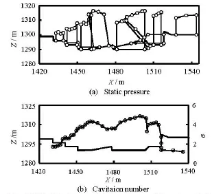
Fig.16 Distributions of static pressure and cavitation number along the center of the bottom of the stilling basin
3.4.3Pressure and cavitation
In the cases of P =1%(Fig.16) and P =5%,the pressures on the bottom and side walls vary from 3.8 m to 27.5 m, 10.4 m to 24.0 m and 0.19 m to 25.4 m, 7.2 m to 19.4 m, respectively and no negative pressure is observed.
The cavitation numbers are much larger than the incipient cavitation number even under the condition that the velocity is 12 m/s everywhere for the sake of safety. In fact, all the velocities near the bottom of the structure are no more than 12 m/s as seen from the velocity field shown in Fig.15. Therefore, the triangular bottom deflector has a better pressure performance than the trapezoidal one. The air entrainment in the high aerated flow and the large cavitation number indicate that the possibility of the cavitaiton erosion of any part of the stilling basin is low.
4. Conclusions
Based on two different scales of physical model tests of the stilling basin optimized with a shallowwater cushion of flood discharging tunnel No. 2 of the Luding hydropower project, the following conclusions can be drawn:
(1) A new type of stilling basin with a water shallow-water cushion and a triangular bottom deflector is proposed to accommodate and solve successfully the lowFr number energy dissipation problem in the Luding Hydropower Project.
(2) The flow pattern with three apparent large eddies identified in the new type of stilling basin is different from the ordinary stilling basin, better hydraulic performances of the hydraulic jump in the new stilling basin are achieved and more importantly, a stable and complete hydraulic jump can be formed when the flow rate varies from small to large.
(3) The new stilling basin can provide a high energy dissipation rate as compared to the traditional one and enjoys a good performance in term of being exempt from the damage of cavitation erosion.
(4) The presented new type of stilling basin can be of engineering interest in similar projects with low Froude number energy dissipation and a large range of flow rates.
Acknowledgments
They are also grateful to the contributions of his colleagues, co-workers and research students, in particular Associate Professor Shen Huan-rong and Engineer YI Wen-min, Sichuan University, China and to Zachary Curtis for his kindly help in careful English proof reading.
References
[1]CHANSON H. Current knowledge in hydraulic jumps and related phenomena[J]. European Journal of Mechanics B/Fluids, 2009, 28(2): 191-210.
[2]ZHANG Hua, LIAN Ji-jian and LIU Fang. Study on the mathematical model of hydraulic jump atomization[J]. Transactions of Tianjin University, 2004, 10(1): 71-76.
[3]NANI G. B. Stilling basin design for low Froude Number[J]. Journal of the Hydraulics Division, 1975,101(7): 901-915.
[4]BEJESTAN M. S., NEISI K. A new roughened bed hydraulic jump stilling basin[J]. Asian Journal of Applied Sciences, 2009, 2(5): 436-445.
[5]RHONE T J. Baffled apron as spillway energy dissipater[J]. Journal of Hydraulics Division, 1977, 103(12):1391-1401.
[6]KATAKAM V., RAMA P. Spatial B-Jump at sudden channel enlargements with abrupt drop[J]. Journal of Hydraulic Engineering, ASCE, 1998, 124(6): 22-28.
[7]OHTSU I., YASUDA Y. and GOTOCH H. Hydraulic condition for undular jump formation[J]. Journal of Hydraulic Research, 2001, 39(2): 203-209.
[8]MOSSA M., PETRILLO A. and CHANSON H. Tailwater level effects on flow conditions at an abrupt drop[J]. Journal of Hydraulic Research, 2003, 41(1):39-51.
[9]YAUSDA Y., TAKAHASHI M. and OHTSU I. Discisson on “Tailwater level effects on flow conditions at an abrupt drop”[J]. Journal of Hydraulic Research, 2005,43(2): 217-224.
[10]LIU Da, LI Lian-xia and HUANG Ben-sheng et al. Numerical simulation and experimental investigation on stilling basin with double shallow-water cushions[J]. Journal of Hydraulic Engineering, 2012, 43(5): 623-630(in Chinese).
[11]SU Pei-lan, LIAO Hua-sheng and LI Tian-xiang. Experimental investigation on hydraulic properties in stilling basin with shallow-water cushion[J]. Journal of Sichuan University (Engineering Science Edition),2009, 41(2): 35-41(in Chinese).
[12]RU Yong-shen, LIAO Hua-sheng and LI Lian-xia et al. Numerical simulation and experimental investigation on stilling basin with shallow-water cushion[J]. Journal of Hydroelectric Engineering, 2010, 29(2): 36-41(in Chinese).
[13]ALIKHANI A., BEHROZI-RAD R. and FATHIMOGHADAM M. Hydraulic jump in stilling basin with vertical end sill[J]. International Journal of Physical Sciences, 2010, 5 (1): 25-29.
[14]SHOLICHIN M., AKIB S. Development of drop number performance for estimate hydraulic jump on vertical and sloped drop structure: A survey of experimental results[J]. International Journal of the Physical Sciences, 2010, 5(11): 1678-1687.
[15]OMID M. H., GORD-NOSHAHRI A. and KOUCHAKZADEH S. 2010. Sill-controlled hydraulic jump in a gradually expanding channel[J]. Proceedings of the ICE-Water Management, 2010, 163(10): 515-522.
[16]ANWAR N., DERMAWAN V. Characteristics of the hydraulic jump on serial drops[J]. International Journal of Academic Research, Part III, 2011, 3(1): 732-736.
[17]ZARE H. K., DOERING J. C. Forced hydraulic jumps below abrupt expansions[J].Journal of Hydraulic Engineering, ASCE, 2011, 137(8): 825-835.
[18]WU Jian-hua, YAO Li and MA Fei et al. Hydraulics of a multiple slit-type energy dissipater[J]. Journal of Hydrodynamics, 2014, 26(1): 86-93.
(January 24, 2014, Revised June 19, 2014)
* Project supported by the National Science Foundation of China (Grand Nos. 51079091, 51209154).
Biography: LI Lian-xia (1978-), Male, Ph. D.,Associate Professor
Corresponging author: LIAO Hua-sheng,
E-mail: liao@egr.msu.edu
杂志排行

水动力学研究与进展 B辑的其它文章
- The analysis of flow characteristics in multi-channel heat meter based on fluid structure model*
- The gas recovery of water-drive gas reservoirs*
- Advances of drag-reducing surface technologies in turbulence based on boundary layer control*
- A review of studies of mechanism and prediction of tip vortex cavitation inception*
- Propulsive performance of a passively flapping plate in a uniform flow*
- System identification mo*delling of ship manoeuvring motion based onεsupport vector regression