Swept-Volume Display System Based on Cylindrical Space Projection and Curved Reflectors
2015-08-07TIANFeng田丰WANGHao汪浩XIAXue夏雪ZHANGWenjun张文俊WANGHe王鹤
TIAN Feng(田丰),WANG Hao(汪浩),XIA Xue(夏雪),ZHANGWen-jun(张文俊),WANG He(王鹤)
1 School of Film&TV Arts and Technology,Shanghai University,Shanghai200072,China
2 Applied Science Lab in GE Healthcare,Shanghai201203,China
Swept-Volume Display System Based on Cylindrical Space Projection and Curved Reflectors
TIAN Feng(田丰)1*,WANG Hao(汪浩)1,XIA Xue(夏雪)1,ZHANGWen-jun(张文俊)1,WANG He(王鹤)2
1 School of Film&TV Arts and Technology,Shanghai University,Shanghai200072,China
2 Applied Science Lab in GE Healthcare,Shanghai201203,China
In order to achieve a clear and steady swept-volume display,the method of swept-volume display based on cylindrical space projection was presented.One projector generated the image volume inπ×70 mm×70 mm×150 mm space.Experimentally,the resolution of images was 800 pixel×600 pixel×360 pixel,which resulted in almost 345 Million voxels.In order to achieve space voxels with uniform brightness,curved reflectors were also designed.In addition,the match conditions between triangles and the scanning p lanes in the volume space were classified and a sweptvolume graphics engine based on embedded p latform was designed.The image rendering the hardware foundation for three-dimensional (3D)dynam ic images generation was achieved.Demonstrated in the experiments,light source utilization of the second-generation system based on curved m irror is about three times brighter than the firstgeneration 3D m initor based on flat m irror,and this system is able to disp lay color,clear and well-proportioned 3D images in brighter room light.
three-dimensional(3D)display;swept-volume display; cylindrical space;voxel
Introduction
In recent years,some world famous companies and universities are developing for new type of 3D display system[1-4].Volumetric displays are the set of threedimensional display technologies that produce volume-filling image[5].Volumetric 3D display is one of themajor3D display techniques[6].Images shown by the volumetric display existing in the real3D world provide all the visual depth information and 360°3D images.These imagesmeet the true vision feelings of people and also meet all physical and psychological view ing needs[3].It isagreed that the volumetric 3D display technique is of great significance and will be well applied in education,scientific and medical research,national defense,and other fields.It also becomes one of new display medias which will change people's daily life.
Based on the display mechanism,volumetric display systems can be roughly divided into two categories:static volumetric display and swept-volume display[7-9].Static volumetric displays create voxels in a geostationary space.One example of static volumetric display uses up-conversion techniques[10-11].In these systems,the display volume is filled with hostmaterials such as crystal that can be selectively excited by two independently controlled radiation beams,which activate a voxel only when they intersect.Radiation beams are usually two kinds of infrared lights with different frequencies and they can be projected by two projectors.Partof the lights through the crystal directly reach the eyes and may cause eye-safe problem[12].Another example of static volumetric display is“DepthCube”from Lightspace Technology[13].This system contains20 stacked liquid crystal scattering shutter panels.In its operation,only one shutter is in scatteringmode at a time,and all other shutters are in transparentmode.It only provides 20 levels of depth at once.On the contrary,in the condition of swept-volume displays,the image space is created by mechanicalmotions of display panels.Images are generated by visible lightswhich do not directly shine into eyes,thus they do no harm to eyes.Except the restriction of the scanning mechanical components,the volume of swept-volume space is not restrained by any other factors.
This paper presents the prototype of a new 3D sweptvolume display developed by a study group in Shanghai University.We name it 3D-PILLAR.This design is improved by optical design based on first version,and realizes color and well-distributed voxels,so the brightness of voxels is basically the same.In addition,a method for matching triangles and scanning planes is provided,which has achieved image rendering and laid the hardware foundation for video generation.
1 System Design of the Swept-Volume Display
1.1 Previouswork
We have focused on the exploration and developmentof the volumetric 3D display based on swept-volume technique in cylindrical space since the year 2008.Several volumetric 3D systems based on LED have been successfully developed by team from East China Normal University(ECNU).Figure 1 shows LED volumetric 3D display system and it is the sweptvolume naked-eye 3D display exhibited in China for the first time.
Previous display systems achieved imaging in large-scale and higher resolution,whose common features are as below:1) imaging space was built in cylindrical space;2)scanning with single LED panel;3)generating voxelswith active luminance. Imaging screen consists of spirale panel[12]or other specialshaped panels.However,visual dead zones always exist no matter what kind of special-shaped panel is used.This fails to express the 360°imaging feature.According to the investigation,most users tend to enjoy the 360°view ing effect.A lthough defects like visual dead zones or voxels unevenly distributed exist in single LED screen display,they can be weakened by improving the imaging material and mapping algorithm.Swept-volume display based on cylindrical space turned out to be the best plan after previous research[9,12,14].
Using high resolution screen scanning method will weaken the influence brought by voxel gray deviation[15].To obtain higher imaging resolution,volumetric 3D imaging based on projection technique is an excellent choice.
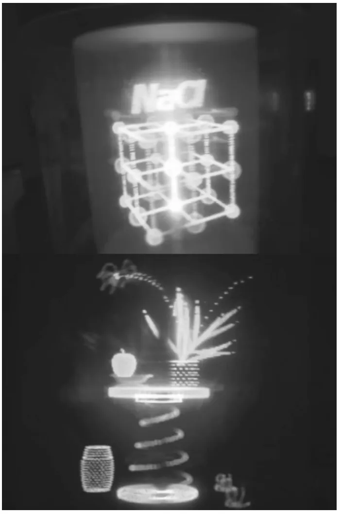
Fig.1 The color 3D displayer based on LED designed by ECNU and Shanghai University Team
1.2 Design of 3D display system based on cylindrical space projection
Schematic diagram of a volumetric display system based on cylindrical space projection is shown in Fig.2(a)[16].The projection screen rotates around the axis driven by the servomotor and forms a cylindrical imaging space.The projector is located at the bottom of the rotary table,and the image is projected on the screen through specular reflection.
In Fig.2(a),about 60%of the display resolution is retained based on dithering technique and stereo images can be obtained under the condition of weaker light in firststage.After the radial linear uniform brightness,luminous flux is retained only 1/3 of the total light source.After the radial nonlinear uniform brightness,lum inous flux is retained only 1/2 of the total lightsource[16].This limits the imaging quality of color3D display.In Fig.2(b),curved reflectors were designed based on the Fig.2(a)prototype for getting all luminous flux of the total light source and projectorwas upgraded to achieve RGB 3-channel color projection in this paper.
System frame of the basic unit is shown in Fig.3.The system consists of field-programmable gate array(FPGA),USB modules,power supply modules,motor drive,servomotor,synchronous belt,mechanical rotary table,projector,mirror,and imaging screen.
FPGA receives commands and data from computer,sends 3D images to the projector,and controls the rotating speed of servomotor according to the settings and data obtained by the sensor in real time.Speed sensor is composed of a set of infrared transm itter and receiver tube.
One revolution of rotary table corresponds to one trigger of the infrared receiver.The rotating speed can be accurately controlled and the projection images can bematched through the internal clock and counter of the embedded system.Besides,there are also two different groups of DC power supplies,among which the 5-voltage one provides power for FPGA,while the 24-voltage one provides for servomotor drive. Servomotor is able to offer 1.47 N·m driving force in conditions of 3 000 r/m in.To acquire 3D images,servomotor works at the speed of 900 r/m in.And transparent Plexiglaswith the thickness of 1 mm is used for the imaging screen to ensure its strength.Through coating on the surface,the screen has half-reflect and half-transmission feature.The imaging space is protected by a cover.
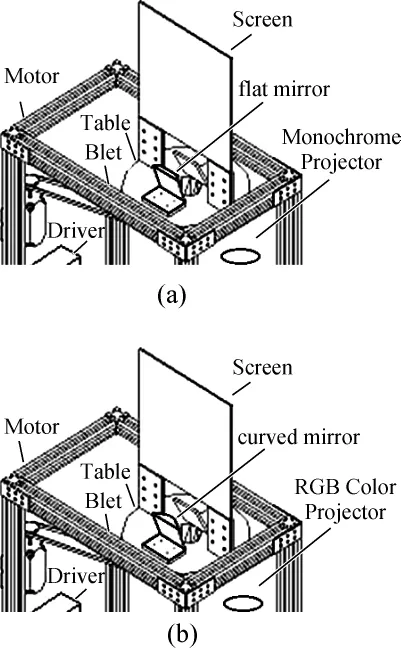
Fig.2 Schematic diagram of a volumetric display system based on cylindrical space projection(a)3D-PILLAR based on flat m irror and(b)enhanced 3D-PILLAR based on curved m irror

Fig.3 System frame of the basic of Fig.2(b)
The volumetric 3D display prototype based on cylindrical space projection is shown in Fig.4.High frame rate projector is the transformation based on the digital light procession(DLP) projector made by Shanghai SVA Light Display Technology Co.,Ltd.,China.Its frame rate is set to 5 400 frames/s.The resolution of digitalmicromirror device(DMD)array is1 024* 768 and diagonal length is17.78 mm.The size ofmicro-mirror is13.68μm×13.68μm.
The driver board is an enhanced DMD development system with the onboard DDR2 memory,and it can project the image over 4 000 Hz repeatedly.With caching,the real-time external trigger function can be supported.DMD driver board has two FPGAs,a DMD driven FPGA and a user-programmable FPGA.

Fig.4 The volumetric 3D display prototype(enhanced 3DPILLAR)on the basis of Fig.2(b)
1.3 Curved reflection structure for uniform and higher brightness
Four planar reflectors are used to project images in the Pespecta 3D system[2].Specular reflection causes voxels unevenly distributed while several reflections lead to low imaging contrast.What's more,inactive positions in volume space bring phenomenon of leaking light.To solve the problem of uniform voxels distribution and reduce reflection time,a new curved reflection structure was designed.
without homogenization,voxels near the central axis of the images based on LED are brighter than peripheral ones (Fig.5(a)).This leads to brightness distortion.Previous methods of homogenizing brightness of voxels have been described in Ref.[7].After applying the pulse w idth modulation,the central brightness and peripheral brightness were basically the same.One complete image in a period of time can be outputted by the projection system,it is impossible to modulate the pulse w idth for each voxel.A non-planar reflector is used in order to homogenize brightness and reduce reflection times.A planar reflector as the centralmirror is titled 45°.Projection beam reaches the non-planar edge reflector through single reflection.The beam reflected by the edge reflector reaches the screen and images.Vertical light area in Fig.5(b)is the output beam of the projector.The first reflection area of this beam lies on the right of the central reflector,which ismarked with brown color.The edge reflector is designed to reflect the evenly distributed light to the uneven imaging screen so that the brightness homogenization in cylindrical space is achieved.The projection origin that we define is the physical location of the projector lens aperture,while themapping origin is themirror point of projection origin by the 45°m irror reflection.
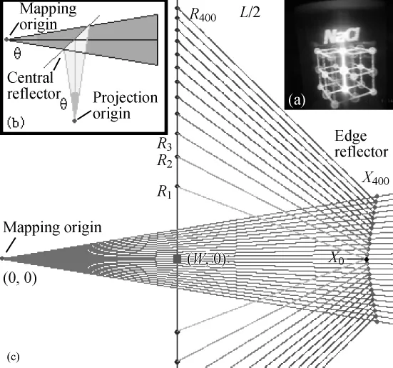
Fig.5 The diagram of light path(a)image with brightness distortion in early LED system,(b)reflection structure and(c) homogenization simulation of horizontal distributed voxels
Considering the horizontal distributed voxels,suppose the distance between the outer area of the voxel,which is the nearest to the central axis,and the central axis is R1.The outer area of the i th voxel is Riaway from the central axis.The area covered by the voxels in different radius in one revolution should be the same to ensure that the voxels in different radius produce similar light intensity.

The distance expression between the outer area of the i-th voxel and the central axis is as follows:

The sum of all the voxels w idth should be equal to the screen w idth L.Supposing the emit position of the projection beam is on the origin and the em itangle of the projection image is known,the horizontal projection beam can bemodeled,and its slope is:

Assuming the initial center position of the reflector is X0which is the intersection position of the first pixel and the reflector.The slope of the reflected light is:

According to the reflection law,to obtain a reflect slope of F1with the incident slope of K1,the slope of the reflector should be S1.

To solve the initial position(X1,K1X1)of the second light through S1,the intersect coordinate can be obtained by iteration.To simplify the iteration,40 pixels are iterated in a group,so 12 control points and its curves are generated.
The horizontally distributed pixels are uneven while the vertically ones are even.Vertical control points of edge reflector are iterated according to the samemethod.Surface carving and coating are donewhile the verticaland horizontal curves are taken into account.The simulation result of voxels homogenization in vertical and horizontal direction is shown in Fig.6.

Fig.6 Homogenization simulation forwhole panel by curved reflector
To supply verification of effectiveness of the edge reflector and show experimental results of improvement in uniformity of brightness,the same picture is projected in one rotation.The image has 32 white pixels arranged in horizontal direction,while others are black pixels.The image is taken from the top of the display and we get the picture as Fig.7 shows.

Fig.7 The distribution map of lum inous energy(a)uneven brightness and brightnessmodel using a conventional plane reflector and(b)uniform brightness and brightnessmodel using an edge curved reflector
In Fig.7(b),the center brightness and peripheral brightness are substantially uniform ly distributed and the design goals are achieved.
2 Graphics Engine for Enhanced 3DPILLAR
3D-PILLAR embedded graphics engine is designed to produce images for 3D-PILLAR from general 3D design tools like 3DMAX,etc.3DS files generated by 3DMAX include vertices and triangles of the model.The block diagram of the 3D-PILLAR embedded graphics engine is shown in Fig.8. First,the 3D-PILLAR graphics engine reads 3DS files through USB module,then coordinate data is normalized.Second,the engine matches the triangles and the scanning plane orderly. Third,voxels are filled after the match points being found. Fourth,voxel data are generated in the Descartes coordinate. The Descartes coordinate is then mapped to polar coordinate,which will be activated.Finally,data transm ission and imaging is accomplished.

Fig.8 The block diagram of the graphics engine
As shown in Fig.9,five matching relationships exist between scanning plane and triangles:scanning plane includes one point on one edge of the triangle;two points on two edges of the triangle;one edge of the triangle;two edges;none.
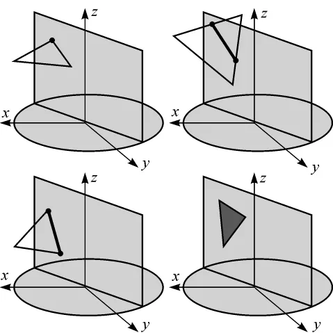
Fig.9 Classification of the match of the triangle and the scanning plane
Suppose the sampling angle of the swept plane isθ according to the swept plane rotating around axis z,and the equation should be generated:

If the step size of the sampling angle isλ,the sampling angle of the swept plane should beθ.

Suppose the 3 vertices of the space triangle are:
V1=(x1,y1,z1),V2=(x2,y2,z2),V3=(x3,y3,z3).
The equations of the three edges are:

Substituting Eq.(8)into Eq.(6),the intersections of lines and swept plane

are expressed as

so xmnand ymnare:

If Eq.(10)is true,Vmn,which lies between Vmand Vn,is a valid matching point.


If only one edge matches the scanning plane,then it will be filled.While if three match the scanning plane,the whole triangle will be filled.The triangle and scanning planematching is completed after the information of vertices of the entiremodel has gotten.
3 Experim ental Results and Analyses
The prototype of this display system has been built to validate the imaging method.Several indoor experiments are designed to test the capability of the entire volumetric 3D display.The rotate speed of the motor is 900 r/min,and the corresponding refresh rate of the images is 15 Hz.Three cameras(CanonEOS5DMARKII)are used to accomplishmultiviewpoint shooting.
The simulation results rendered by graphics engine under ideal condition are shown in Fig.10(b).While Fig.11 shows the same 3D image from three viewpoints.This experiment utilizes voxels filling rendering algorithm.The objects imaging with 3D depth sense is achieved.The image resolution is800× 600×360,resulting in almost 345 million voxels.Different parts of the clear and stable image can be observed in different viewpoints in brighter room light.This means,panoramic naked-eye observations in all viewpoints are obtained.
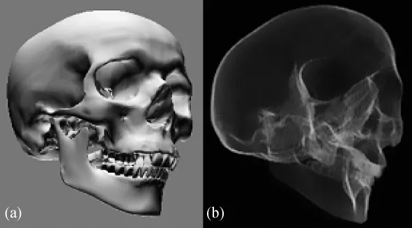
Fig.10 Simulation result for swept-volume display(a) Module in 3D MAX and(b)simulation result rendered by graphic engine under ideal condition
Although the initial experiments have produced images successfully,there are still other ways to improve the performance of the display.
We will thenmeasure rendering time of single body frame and achieve rendering in real-time.Since the light is scattered in a space rather than in a plane,the volume space image brightness by using the conventional projection light source is greatly reduced compared with the planar image.Volume 3D image requires the display panel provides themaximum view ing angle and function of half-transm ission half-reflection,which greatly reduce the brightness of a single viewpoint.By increasing the brightness of the projector light source,the brightness of the volume 3D display can be increased.To implementmoving 3D images display,parallel rendering engine with multi-matchesand filling units are used.The system can be updated to three-color imagery by usingmultiple projectors.All the efforts aimed at improving the system are currently under way.

Fig.11 Color,uniform and higher brightness3D images in brighter room light by enhanced 3D-PILLAR
4 Conclusions
In this paper,we have presented a novel volumetric display based on cylindrical space projection.High-resolution images with 345 million voxels can be generated by utilizing steady machine.The images produced by the display were exact,clear,and steady in the indoor environment.We confirmed stereoscopic image generation without any glasses,in which all the stereoscopic visual factors were satisfied.All luminous flux of the total light source is got by enhanced 3D-PILLAR.Light source utilization of enhanced 3D-PILLAR is about three times brighter than the first-generation 3Dmonitor based on flatmirror. The enhanced 3D-PILLAR has been applied to aerospace field by the project of Shanghai Committee of Science and Technology. To obtain dynamic 3D images,further improvements can be made for the display system in the future such as hardware parallel feature optimizing real-time embedded graphics engine.
[1]Sun CW,Chang XW,CaiM M,et al.An Improved Design of 3D Swept-Volume Volumetric Display[J].Journal of Computers,2014,9(1):235-242.(in Chinese)
[2]Jones A,McDowall I,Yamada H,et al.Rendering for an Interactive 360°Light Field Display[J].ACM Transactions on Graphics,2007,26(3),doi:10.1145/1276377.1276427.
[3]「デジタルコンテンツEXPO2009」出展のご案内[DB/OL]. (2009)[2014].http://www.sony.co.jp/SonyInfo/News/ Press/200910/09-123/.
[4]Cossairt O S,Napoli J,Hill S L,et al.Occlusion-capable Multiview Volumetric Three-dimensional Display[J].Applied Optics,2007,46(8):1244-1250.
[5]Lanman D,Wetzstein G,Hirsch M,et a l.Polarization Fields: Dynamic Light Field Display using Multi-Layer LCDs[J].ACM Transactions on Graphics,2011,30(6),doi:10.1145/ 2070781.2024220.
[6]Favalora G E,Napoli J,Hall D M,et al.100 Million-voxel Volumetric Display[C].Proceedings of SPIE Cockpit Displays IX:Displays for Defense Applicatiaons,Orlando,FL,USA,2002,4712:300-312.
[7]Hong J,Kim Y M,Choi H J,et al.Three-Dimensional Display Technologies of Recent Interest:Principles,Status,and Issues[J].Applied Optics,2011,50(34):H87-H115.
[8]Gately M,Zhai Y,Yeary M,etal.A Three-Dimensional Swept-Volume Display Based on LED Arrays[J].Journal of Display Technology,2011,7(9):503-513.
[9]M iyazaki D,Honda T,Ohno K,et al.Volumetric Display System Using a Digital M icromirror Device Based on Inclined-Plane Scanning[J].Journal of Display Technology,2010,6 (10):548-552.
[10]Tian F,Xu JM,Liu J G.Realization of Low Cost True 3D Volumetric Display System[J].Journal of East China Normal University,2009(4):115-123.(in Chinese)
[11]Refai H H.3D Images Using Space Display for Air Traffic Control Applications[J].Journal of Display Technology,2011,7(4):186-192.
[12]Liu X F,Dong G P,Qiao Y B,et al.Transparent Colloid Containing Upconverting Nanocrystals:an Alternative Medium for Three-Dimensional Volumetric Display[J].Applied Optics,2008,47(34):6416-6421.
[13]Geng J.Volumetric 3D Display for Radiation Therapy Planning[J].Journal of Display Technology,2008,4(4):437-450.
[14]Sullivan A.3-Deep:New Displays Render Images You Can Almost Reach Out and Touch[J].IEEE Spectrum,2005,42 (4):30-35.
[15]Tian F,Wang H,Fang Y Y,et al.A Swept Volume Display System Using a Planetary Gear Structure Based on ParallelMoving[J].Journal of Display Technology,2012,8(8):457-463.
[16]Tian F,Xia X,Tian J,et al.The Voxelization and Homogenization Methods of High-Resolution[J].Journal of Computer-Aided Design of Computer Graphics,2013,25(9): 1304-1311.(in Chinese)
If only onematching point is valid,then fill it.If two are valid,then fill all the pixels between them.However,if none of thematching points is available,no filling process is needed. If Eq.(11)is satisfied,there will be one or three edgesmatch the swept plane.
TP391.9
A
1672-5220(2015)04-0672-06
date:2014-05-06
Shanghai Comm ittee of Science and Technology,China(No.14511108200)
*Correspondence should be addressed to TIAN Feng,E-mail:ouman@shu.edu.cn
猜你喜欢
杂志排行
Journal of Donghua University(English Edition)的其它文章
- Empirical Analysis of Binary Logistic Model for the Influencing Factors of the Chinese Urban and Rural Residents'Woolen Products Consumption—Based on Questionnaires of 513 Urban and Rural Residents in 16 Provinces
- Analysis of Satisfaction with Business Cost in Shanghai Using Structural Equation Modeling Approach
- Ontology Mapping Based on Bayesian Network
- Diurnal and Seasonal Variations in Particulate Matter at Shanghai during the Heavy Haze and Non-haze Periods
- Existence of Solutions for Infinity-Point Nonlinear Fractional Boundary Value Problem at Resonance
- Human Mouth-State Recognition Based on Image Warping and Sparse Representation Combined with Homotopy
