Investigation on experimental method of low-impedance materials using modified Hopkinson pressure bar
2015-04-22MIAOYinggang苗应刚LIYulong李玉龙DENGQiong邓琼TANGZhongbin汤忠斌HUHaitao胡海涛SUOTao索涛
MIAO Ying-gang(苗应刚), LI Yu-long(李玉龙), DENG Qiong(邓琼),TANG Zhong-bin(汤忠斌), HU Hai-tao(胡海涛), SUO Tao(索涛)
(School of Aeronautics, Northwestern Polytechnical University, Xi’an 710072, China)
Investigation on experimental method of low-impedance materials using modified Hopkinson pressure bar
MIAO Ying-gang(苗应刚), LI Yu-long(李玉龙), DENG Qiong(邓琼),TANG Zhong-bin(汤忠斌), HU Hai-tao(胡海涛), SUO Tao(索涛)
(School of Aeronautics, Northwestern Polytechnical University, Xi’an 710072, China)
To increase the detectability of split Hopkinson pressure bar (SHPB) of low-impedance materials, modifications were conducted on traditional SHPB apparatus with a PMMA tube to output transmitted signal, and weak signals were further amplified by semiconductor strain gauges . Experiments on soft rubbers and cushioning foam materials were carried out. In order to analyze the accuracy of the experimental results, the stress equilibrium issues involved in the assumptions of SHPB were investigated. First, by way of re-constructing loading process of incident wave, the stress-strain curve was obtained, along with the stress equilibrium ratio of specimen. Secondly, the influences on the accuracy of stress-strain curves were investigated through the elastic modulus comparisons. And the results illustrate that the bilinear incident wave from experiments can ensure the stress equilibrium deformation of specimen after 2 normalized times, much sooner than ramp incident waves. Moreover, it even facilitates specimen deformation with a constant strain rate. The results confirm that the detectability of the modified SHPB can be down to tens kPa with enough accuracy level.
SHPB; low-impedance materials; bilinear wave; stress equilibrium; constant strain rate
Low mechanical impedance materials have gotten more and more popularizations for specific applications. For example, kinds of foam material and sandwiched composites have been widely used in automatic, even aerospace industries for their high specific weight and strength; soft rubbers are employed in portable electronic devices for absorbing impact energy. Thus, for higher level of security and severability of the related devices/structure, it is necessary to model and analyze their mechanical behaviors of materials involved in situations such as impacting. It is indispensable to require a full understanding of their mechanical responses, especially under dynamic loading. The traditional loading technique, such as the split Hopkinson bar, is widely used to measure the dynamic behavior of materials under impact loading. It was originally designed for measuring transient explosive wave by Hopkinson[1], and revolutionarily modified by Davies[2], and Kolsky[3]to test dynamic behavior of materials under high strain rate.
In the last decades, great progresses had been made in the Hopkinson bar techniques on low impedance materials. Actually, it is very difficult to conduct experiments on these kinds of materials using split Hopkinson pressure bar (SHPB), because their mechanical strength is usually much lower than that of metal specimen, at least by one or two orders, leading to very weak transmitted signals that can hardly be detected. In order to amplify the weak signals, related techniques were utilized to enhance the transmitted signal, which used an aluminum tube to output the transmitted signals as well as higher-sensitivity strain transducers such as the quartz-crystal sensor or semiconductor strain gauges for much low-impedance materials to measure the weak transmitted signals[4-6]. Besides, viscous-elastic Hopkinson bars were also established to measure the low-impedance materials with the aid of analytical solutions to wave dispersion in viscous-elastic bar[7-9]. However, data interpretation involved with complicated solution of wave dispersion in viscous-elastic Hopkinson bar, which confronted its applications.
An alternative difficulty was to design the incident wave, for ensuring the accuracy of stress equilibrium in the specimen. For low-impendence materials, achieving equilibrium deformation as soon as possible is essential for the accuracy level of experimental results. Ravichandran[10]concluded that the specimen could achieve a stress equilibrium when the ramp loading incident wave reverberated in the specimen for 3 times. But the duration still would be too long, for the reason that the wave speed of soft materials was lower than that of normal engineering materials by one or two orders. After analyzing the effect of the rising edge of incident wave, Yang[11]found that the time duration to achieve specimen uniformity of stress can be shortened if the incident wave had a specific profile. However this kind of wave has not been reported experimentally so far.
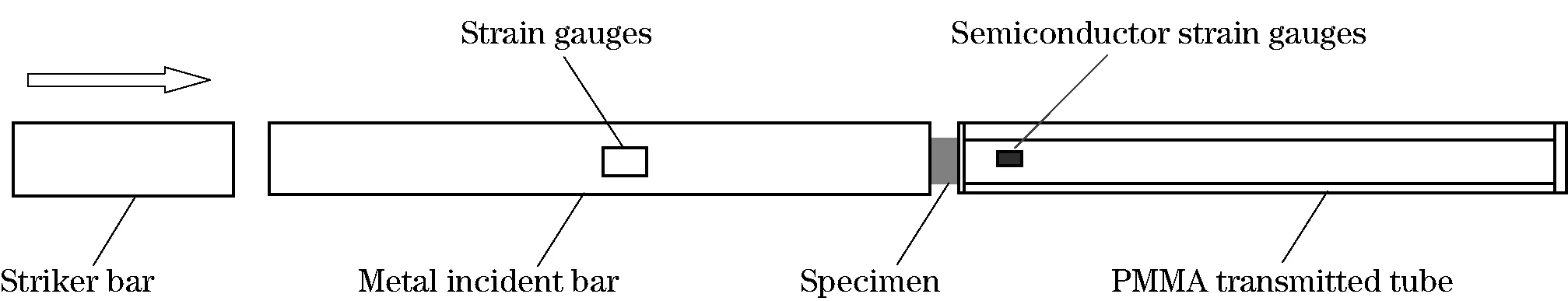
Fig.1 Modified split Hopkinson bar apparatus for low-impedance materials
Moreover, inertial radial effect under dynamic loading is essential to distinguish from quasi-static loading. In the past decades, Kolsky[3], Davies[12], and Gorham[13]investigated the specimen stress after well considering inertial effects and found that in a constant strain rate it can reduce greatly the inertial effect. Warren[14]commented on the radial inertial effect and found that, for soft materials such as foams, rubber with low flow stress, the radial inertial should be considered. Only in the case of specimen deformation under constant strain rate loading, the inertial term could be reduced, even eliminated[3, 12-13].
This paper focused mainly on issues involved in measuring soft materials using SHPB techniques.We proposed a modified SHPB apparatus, with the metal-incident bar, and the PMMA tube as transmitted bar. Tests were conducted with the aid of the pulse shaping technique for stress equilibrium and constant strain rate. Meanwhile, stress equilibrium issues were analyzed elaborately and the corresponding numerical calculations were carried out to ascertain the influence of stress equilibrium on the accuracy of experimental results.
1 Modified SHPB and Experiments
1.1 Modified SHPB
In order to amplify the transmitted signals, in the present work we proposed a modified Hopkinson bar configuration as shown in Fig.1. A PMMA transmitted tube as well as high sensitivity-factor semiconductor strain gauge (gauge factor up to 150) was adopted to further improve the detectability of transmitted signals. The semiconductor strain gauges were cemented closely to the interface of specimen/tube, with 50 mm far away. A PMMA pad with size ofφ15 mm×3 mm was fixed on the ends of the transmitted tube, to support the sandwiched specimen deformation. The traditional aluminum incident bar was still used.
Fig.2 shows the sandwiched section, where the contacting interfaces are labeled as 1 and 2. The stresses and displacements in interfaces 1 and 2 were deduced as follows.

Fig.2 Sandwiched section of split Hopkinson pressure bar
The stress, strain and strain rate of the specimen were deduced based on one-dimension stress wave theory[15].
(1)
whereεi(t),εr(t) andεt(t) were the incident wave, the reflected wave, and the transmitted wave respectively;CBandCTwere the wave speed of incident bar, and the PMMA tube, respectively; andls. was the specimen length. Thus the strain of specimen could be calculated by
(2)
Thentheaveragestressinthespecimen
couldbeexpressed:
(3)
whereAB,AT,Aswere the area of the incident bar, the transmitted tube and the specimen, respectively. AndEB,ETwere the elastic modulus of the incident bar and the transmitted tube, respectively. Then the equations were obtained below:
(4)
1.2Experimentdetails
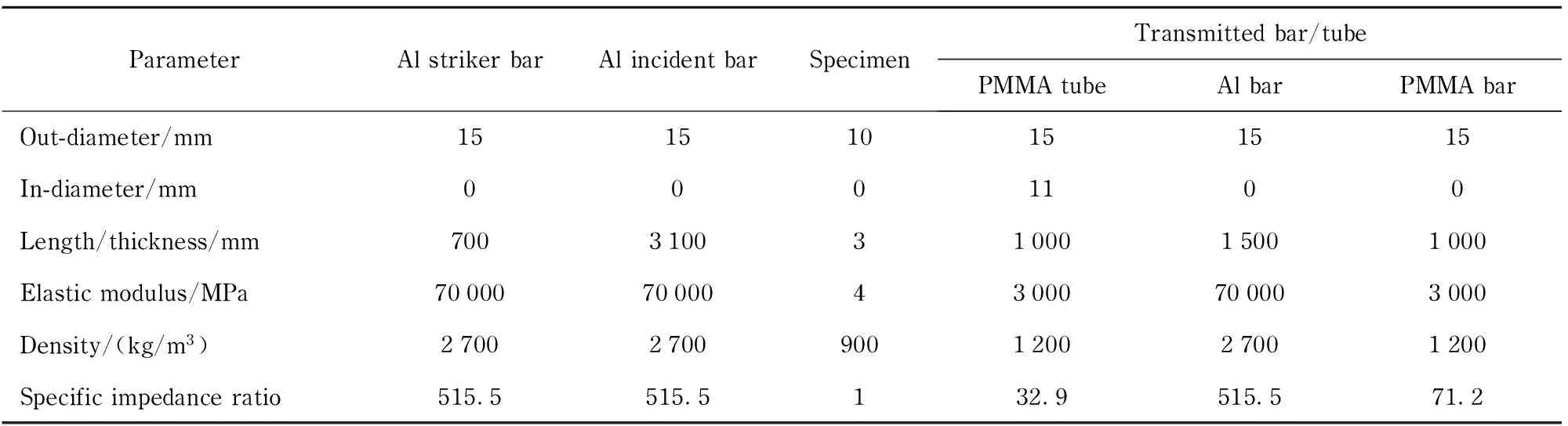
Tab.1 Dimensions and mechanic parameters of SHPB and specimen
The specific impedance ratios were the relative impedance values of related bars to the rubber specimen. Specific pulse shapers, superimposed by multilayers tissue and plasticine, were utilized to elongate the rising time of incident wave[16-17]. The incident wave could be trimmed to achieve wave duration about 400 μs with the rising time of about 90 μs, as shown in Fig.3. The corresponding reflected and transmitted waves are also shown in Fig.3.
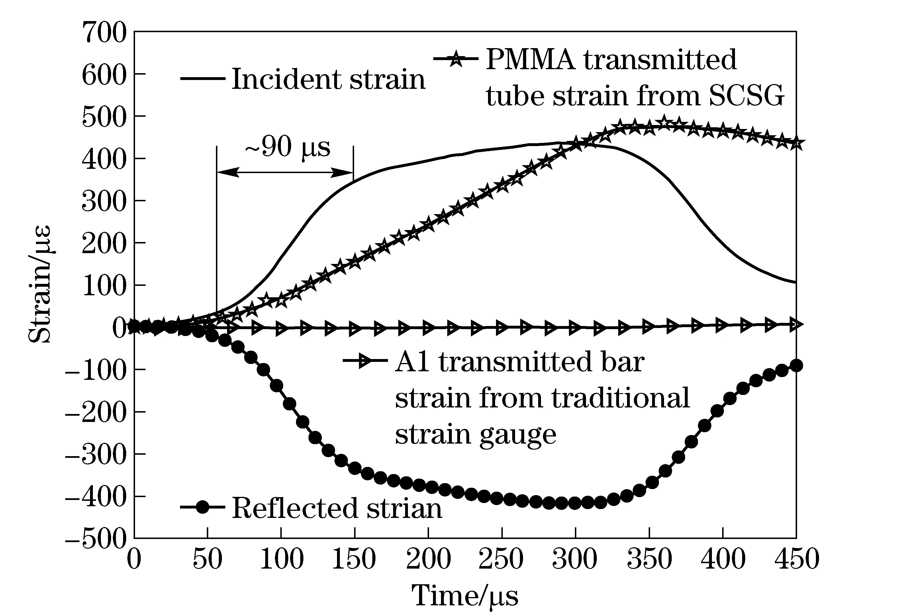
Fig.3 Strain signals from modified SHPB
It can be observed that the transmitted strain signal had been amplified to be in the same order with the incident wave and reflected wave. Similar tests were also conducted using a traditional Hopkinson pressure bar, which used an aluminum bar as the transmitted bar, and the traditional strain gauge to record strain signals. The transmitted strain signal from the traditional aluminum bar was displayed in Fig.3 too. It was hard to distinguish the transmitted strain signal due to its strong weakness. Based on the amplitude of PMMA tube strain from semiconductor strain gauge, it can be calculated that the strain in the aluminum transmitted bar was 7 μεaround. It was in the same order as the noise signal, even covered by the noise.
Besides, in order to checkthe potential detectability of this SHPB, a lower impedance material, a cushioning foam was selected as specimen, and experiments were performed with the size of 8.6 mm×9.1 mm (as shown in Fig.4), and 2.5 mm in thickness. The loading condition was the same as that of rubber specimen experiments. Namely, the incident wave was also trimmed to be the same as that of Fig.3.
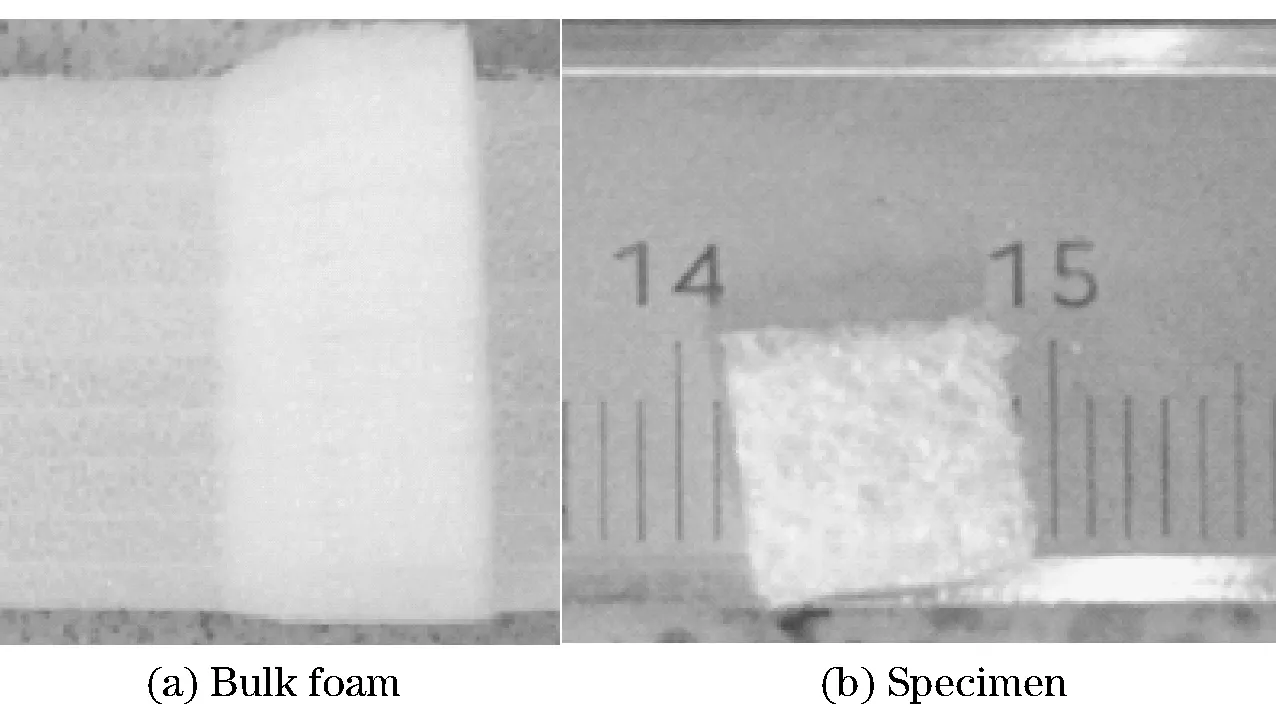
Fig.4 Cushioning foam specimen
2 Results and discussions
2.1 Experimental results
The true stress-strain curve of rubber specimen and corresponding strain rate were shown in Fig.5. The fitted slope of stress-strain curve was nearly 4 MPa withinεt=0.10,R2=0.962 6 (whereRis correlation coefficient in the least squares method for linear regression). The deformation of specimen had come into nearly a constant strain rate sinceεt=0.10, and the strain rate was around 1 350 s-1.

Fig.5 True stress-strain curve and accompanying strain rate of soft rubber
Fig.6 showed the stress-strain curve and accompanying strain rate of the cushioning foam specimen. It came into compacting with the increasing loading. The engineering stress was given for quantifying its mechanical behaviors. It was found that the stress of specimen was lower than 0.06 MPa untilεt=0.45. The fitted slope of stress-strain curve was 0.136 3 MPa withinεt=0.15. The deformation of specimen had come into an approximate constant strain rate sinceεt=0.15, and the strain rate was around 1 880 s-1. Thus it confirmed the detectability of this modified split Hopkinson bar apparatus, which might can test materials with strength down to tens kPa.

Fig.6 True stress-strain curve and strain rate of the cushioning foam specimen
In the aforementioned results, although the stress-strain curves and constant strain rates were obtained by utilizing the proposed apparatus, whether the results were the real performances of materials or not are still unknown. Thus the assumptions of the proposed SHPB were needed to be analyzed, especially in the stress equilibrium issue.
2.2 Formula derivation for analyzing stress equilibrium
In order to analyze loading procedures of stress wave in specimen, the numerical calculation to re-construct the actual loading process was conducted by computing the stresses and displacements in interfaces 1 and 2, where the reflecting and transmitting of the loading stress wave occurred.
Fig.7 elaborately shows the actual process of waves’ reflecting and transmitting at both interfaces. Here we defined the normalized timeτ=ls/cs, which was the time needed for the stress wave to propagate between interfaces, wherelsandcsare the length and wave speed of specimen respectively. The reflected coefficientsF, and the transmitted coefficientsTare calculated based on one-dimensional stress wave theory[18]and are listed in the below:
(5)
whereTBSmeans the transmitted coefficient of stress wave from bar to specimen, and then the label strategy could be applied to other coefficients. The stress at the interfaces between bars and specimen could be deduced as following:
(6)
(7)

Fig.7 Waves’ reflecting and transmitting at interfaces of specimen and bars
Here,aparameterR(t) was defined to evaluate the state of stress disequilibrium in specimen as below[10]. It was universally considered to be in a stress equilibrium, whenR(t) were lower than 5%[10]. In the following sections, the stress disequilibrium factor will be used to determine whether the stress equilibrium is achieved in the specimen.
(8)
2.3Numericalcalculation
Thenumericalcalculationswereconductedontheabove-mentionedsoftrubberspecimen.Theincidentwavepresentedabinary-linearconfiguration,whichwasabstractedfromtheincidentwaveofFig.3.TheparametersofHopkinsonbarandspecimenweredeterminedfromTab.1.Thespecimenwasendowedtobelinearelasticperformanceforsimplifyingthecalculation.Thenormalizedtimewhichisabout45 μs was calculated based on its elastic modulus, density and its length. The loading details were plotted in Fig.8 together with related stress equilibrium ratios. This specific loading with the turning point at 2 normalized times facilitated the stress equilibrium ratio coming down to values below 5% quickly. That is, the rubber specimen could come into stress equilibrium deformation quickly just after 2τ.
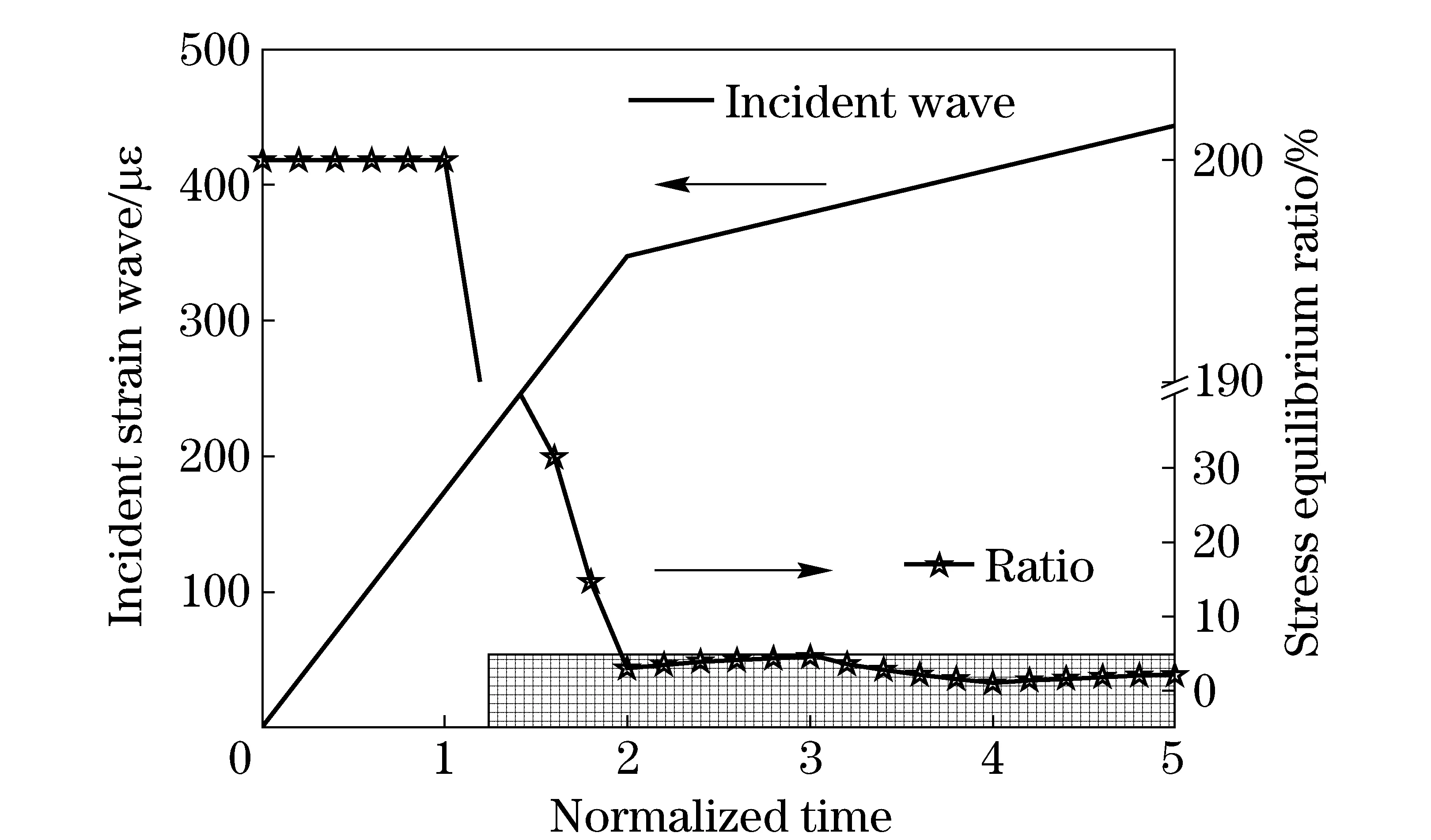
Fig.8 Abstracted binary-linear incident wave and its stress equlibrium ratios
In order to highlight the advantage of bilinear incident wave, additional calculations were also carried out for the PMMA transmitted tubes, PMMA transmitted bar, and aluminum bar, under ramp incident wave loading. The stress equilibrium shared the same tends with the results of the reference[10]. Within normalized time 2τ, the ratios were fully larger than 5%. After that, they were mostly larger than 5% before 5τ. Since then, the specimen could arrive in a stress equilibrium stage. For the involved transmitted bars or tube, there were few differences with the stress equilibrium ratio (as shown in Fig.9), even the specific impedance ratios mismatch dramatically from 515.5 of Al bar to 1 of specimen, as listed in Tab.1. After comparing the ramp wave with bilinear wave, and their influence on the stress equilibrium ratios, it can be concluded that under the bilinear wave loading, the lower slope of the second-linear loading after 2τplays an important role in meeting the requirement of stress equilibrium ratio coming down to values below 5%.

Fig.9 Ramp loading incident wave’s configuration, and stress equilibrium ratios
In a word, the rubber specimen could achieve stress equilibrium deformation with this nearly bilinear loading wave. This specific loading wave could facilitate specimen stress equilibrium deformation very sooner.
2.4 Influence of the stress equilibrium
The specimen underwent severe deformation of stress disequilibrium state at the very beginning of deformation. The influence of disequilibrium deformation on the stress-strain curves should be worthy of knowing, for it may affect the accuracy of stress strain curve, especially the elastic modulus determination of linear behavior of materials. Thus, based on the reconstructing procedures, the stress-strain curves were re-constructed by Eqs.(4)(6). The parameters and size of bar and specimen were shown in Tab.1. The loading wave was the binary-linear wave from experiments of rubber materials, namely same with the incident strain wave of Fig.8.
The fitted elastic modulus was obtained by fitting the reconstructed stress-strain curve, which were displayed in Fig.10. For the input elastic modulus 4MPa, the 5% error zone was between 3.8 MPa to 4.2 MPa. Within the loading duration between 2τto 5τ, the modulus were in the 5% error zone. Even with 2τwhen specimens had just undergone severe disequilibrium deformation, the fitted modulus were 4.157 MPa, by only about 4% error more than the input modulus 4 MPa. So with this bilinear incident wave, Eq.(4) could interpret the stress, strain as well as strain rate history with enough accuracy.
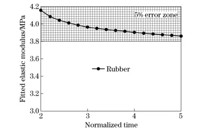
Fig.10 Trends of fitted elastic moduli of rubber and stress equilibrium ratio with normalized time

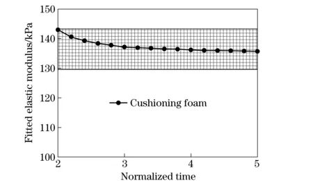
Fig.11 Trend of fitted elastic modulus of cushioning foam specimen versus normalized times
3 Remarking and conclusions
In this paper, a PMMA tube was selected as a transmitted bar to measure the weak transmitted signal due to low impedance of tested materials. Meanwhile, the semiconductor strain gauge with its gauge factor much higher than the traditional strain gauge by 75 times was adopted to further amplify the transmitted signals. Due to the low-impedance of specimen, the normalized time of specimen would be much longer than that of traditional metal. Thus it would take a long time to achieve the stress equilibrium deformation of specimen. Fortunately, the bilinear incident wave can facilitate the specimen deformation to come into stress equilibrium state after 2τ. For the low-impedance specimen with linear elastic behavior, the stress disequilibrium influence on the stress-strain curve was negligible, with error in 5% from, in the view of elastic modulus determination accuracy. That is, the bilinear loading wave can be adopted in SHPB experiments of the low-impedance materials, with the advantages of both achieving a stress equilibrium sooner with constant strain rate deformation. Therefore, the proposed apparatus could be used to measure the dynamical behavior of some low impedance materials with detectability down to tens kPa.
[1] Hopkinson B. A method of measuring the pressure in the deformation of high explosives or by the impact of bullets [J]. Philosophical Transactions of the Royal Society of London,1914,A213:437-452.
[2] Davies R M. A critical study of Hopkinson pressure bar[J]. Philosophical Transactions of the Royal Society of London,1948, A240:375-457.
[3] Kolsky H. An investigation of the mechanical properties of materials at very high rates of loading[J]. Proceedings of the Royal Society ofLondon, 1949,B62:676-700.
[4] Chen W, Zhang B, Forrestal M J. A split Hopkinson bar technique for low-impedance materials[J]. Experimental Mechanics, 1999,39(2):81-85.
[5] Chen W, Lu F, Zhou B. A quartz crystal imbedded split Hopkinson bar for softmaterials[J]. Experimental Mechanics, 2000,40:1-6.
[6] Trautmann A, Siviour C R, Walley S M, et al. Lubrication of polycarbonate at cryogenic temperatures in the split Hopkinson pressure bar [J]. International Journal Impact Engineering, 2005,31:523-544.
[7] Zhao H, Gary G, Klepaczko J R. On the use of a viscoelastic split Hopkinson pressure bar[J]. International Journal Impact Engineering, 1997,19:319-330.
[8] Wang L, Labibes K, Azari Z, et al. Generalization of split Hopkinson bar technique to use viscoelastic bars[J]. International Journal Impact Engineering, 1994,15:669-686.
[9] Zhao H, Gary G. A three dimensional analytical solution of the longitudinal wave propagation in an infinite linear viscoelastic cylindrical bar: application to experimental techniques[J]. Journal of the Mechanics and Physics of Solids, 1995,43(8):1335-1348.
[10] Ravichandran G, Subhash G. Critical appraisal of limiting strain rate for compression testing of ceramics in a split Hopkinson pressure bar[J]. Journal of America Ceramic Society, 1994,77(1):263-267.
[11] Yang L M, Shim V P M. An analysis of stress equilibrium uniformity in split Hopkinson bar test specimens[J]. International Journal Impact Engineering, 2005,28:129-150.
[12] Davies E D H, Hunter S C. The dynamic compression testing of solids by the method of the split Hopkinson pressure bar[J]. J Mech Phys Solids, 1963,11:155-179.
[13] Gorham D A. Specimen inertia in high strain-rate compression [J]. J Phys D Appl Phys, 1989,22:1888-1893.
[14] Warren T L, Forrestal M J. Comments on the effect of radial inertial in the Kolsky bar test for an incompressible material[J]. Experimental Mechanics, 2010,50:1253-1255.
[15] Lindholm U S. Some experiments with split Hopkinson pressure bar [J]. Journal of the Mechanics and Physics of Solids, 1964,12(3):317-335.
[16] Frew D J, Forrestal M J, Chen W. Pulse shaping techniques of testing brittle materials with a split Hopkinson pressure bar [J]. Experimental Mechanics, 2002,42(1):93-106.
[17] Yuan Q L, Li Y L, Li H J, et al. Quasi-static and dynamic compressive fracture behavior of carbon/carbon composites [J]. Carbon, 2008,46:699-703.
[18] Wang L L. Foundations of stress waves[M]. Amsterdam: Elsevier,2007: 69-70.
(Edited by Wang Yuxia)
10.15918/j.jbit1004- 0579.201524.0220
O 347.3 Document code: A Article ID: 1004- 0579(2015)02- 0269- 08
Received 2014- 04- 29
Supported by the National Natural Science Foundation (11272267, 11102168, 10932008);111 Project ( B07050)
E-mail: suotao@nwpu.edu.cn
猜你喜欢
杂志排行

Journal of Beijing Institute of Technology的其它文章
- Numerical simulation of effects of operating conditions on the molecular weight of polypropylene using a response surface method
- Efficient and fair resource allocation in downlink OFDMA systems
- Effect of cutting speed on residual stress of special coating during remanufacturing
- Un-powered gliding aircraft’s ballistic missile optimal design
- Quantification of CP4-EPSPS in genetically modifiedNicotianatabacum leaves by LC-MS/MS with 18O-labeling
- Effect of solvent on the crystal morphology of royal demolition explosive