Slow driving control of tracked vehicles with automated mechanical transmission based on fuzzy logic
2015-04-22JINHui金辉WANGJunliang王军亮MIAOChengsheng苗成生
JIN Hui(金辉), WANG Jun-liang(王军亮), MIAO Cheng-sheng(苗成生)
(School of Mechanical Engineering, Beijing Institute of Technology, Beijing 100081, China)
Slow driving control of tracked vehicles with automated mechanical transmission based on fuzzy logic
JIN Hui(金辉), WANG Jun-liang(王军亮), MIAO Cheng-sheng(苗成生)
(School of Mechanical Engineering, Beijing Institute of Technology, Beijing 100081, China)
In order to move tracked vehicles at an extremely slow speed with automated mechanical transmission (AMT), slow driving function was added in the original system. The principle and requirement of slow driving function were analyzed. Based on analysis of slow driving characteristic, identification of slow driving condition and fuzzy control algorithm, a control strategy of the clutch was designed. In order to realize slow driving, the clutch was controlled in a slipping mode as manual driving. The vehicle speed was increased to a required speed and kept in a small range by engaging or disengaging the clutch to the approximate half engagement point. Based on the control strategy, a control software was designed and tested on a tracked vehicle with AMT. The test results show that the control of the clutch with the slow driving function was smoother than that with original system and the vehicle speed was slower and steadier.
slow driving; automated mechanical transmission (AMT); fuzzy logic; control strategy
Automated mechanical transmission (AMT) is based on the dry clutch and the mechanical transmission. The vehicle speed must be very slow in some special conditions, such as moving into a garage, working accurately, assembling the track. If AMT has no slow driving function, the vehicle must be controlled to start and stop frequently, which easily makes the drivers fatigue. At the same time, the vehicle speed is not steady and the passengers may be uncomfortable. In older to improve the performance of an AMT system, the study of slow driving function is essential.
Slow driving means that the speed of the vehicle is lower than the minimum stable speed. The recognition of drivers’ intention and control strategy are fully important to realize slow driving. Researches focus on the study of control strategy, but ignore the drivers’ intention[1-3].
The existed automated clutch actuators of AMT include hydraulic actuator, pneumatic actuator and electric actuator. Among them, the hydraulic one is the most widely used in tracked vehicles[4-6]. Based on hydraulic actuator, a slow driving control system is developed. After adding slow driving control strategy into the original control software, the vehicle can start well in different road conditions during the tests.
1 Analysis of slow driving characteristics
1.1 Control characteristics of drivers
Operation of AMT means the engine, clutch and transmission work together[7]. The system can obtain a few signals: position of accelerator pedalYp, rotation speed of engineNe, rotation speed of the transmission input shaftNi, rotation speed of the transmission output shaftNo, clutch displacementLcd, brake signal BK.
Slow driving function of AMT should try to meet the driver’s requirements. According to the driver’s demand for vehicle speed, the driver controls the accelerator pedal and the brake pedal timely in slow driving. Under normal circumstances, the transmission is in the lower gear and theYpis no more than 10%, except in special conditions, such as on the slope. There is no or a lighter brake under the condition when the vehicle speed meets the driver’s demand.
1.2 Analysis of slow driving characteristics
1.2.1 Main parameters of powertrain
The main parameters of the tested vehicle are as follows.
Engine idle speed (Nei): 550-650 r/min; first gear ratio of transmission (ifg): 3.0; vehicle weight (G): 1.332 8×10⁵N; driving wheel radius (Rk):265.4 mm; the side transmission radius (is): 5.5 mm; external diameter of friction plate (D): 348 mm; inner diameter of friction plate (d): 304 mm; numbers of clutch friction pair (Z): 10; maximum clutch displacement (Lcdmax): 13 mm; minimum clutch displacement (Lcdmin): 0 mm.
1.2.2 Dynamic analysis of slow driving stage
Slow driving mainly includes two stages: from zero to target speed and minor speed adjustment.
① The first stage
The first stage contains engaging the clutch and slipping the clutch. The clutch transmits no torque in eliminating the gap:
(1)
whereMeis engine output torque (N·m);Ieis inertia of engine flywheel, transmission case and active component of the main clutch (kg·m2); ωeisangularvelocityoftheengineshaft(rad/s); ωiisangularvelocityofthetransmissioninputshaft(rad/s).Intheinitialstageofslipping,thevehicledoesnotstartupsincethedrivetorqueislessthanthedragtorque:
(2)
whereMtis drive torque of the clutch transmitted (N·m).
With the clutch engaging, the drive torque is bigger and bigger. When it is more than the drag torque, the vehicle will start up:
(3)
whereMiis drag torque of the vehicle resistance converted to the transmission input shaft (N·m);Iiis inertia of vehicle quality converted to transmission input shaft (kg·m2).
② The second stage
In this stage, the system mainly controls the clutch disengage or engage properly to adjust vehicle’s speed. To keep the speed stable, the drive torque must be controlled in a small range, and it is nearly to the drag torque. The dynamic equation of this stage is the same as Eq.(3). The difference is thatMtis bigger thanMiin the first stage whileMtmay be smaller thanMiin the second stage.
1.3 Analysis of the automated clutch characteristics
1.3.1 Control principle
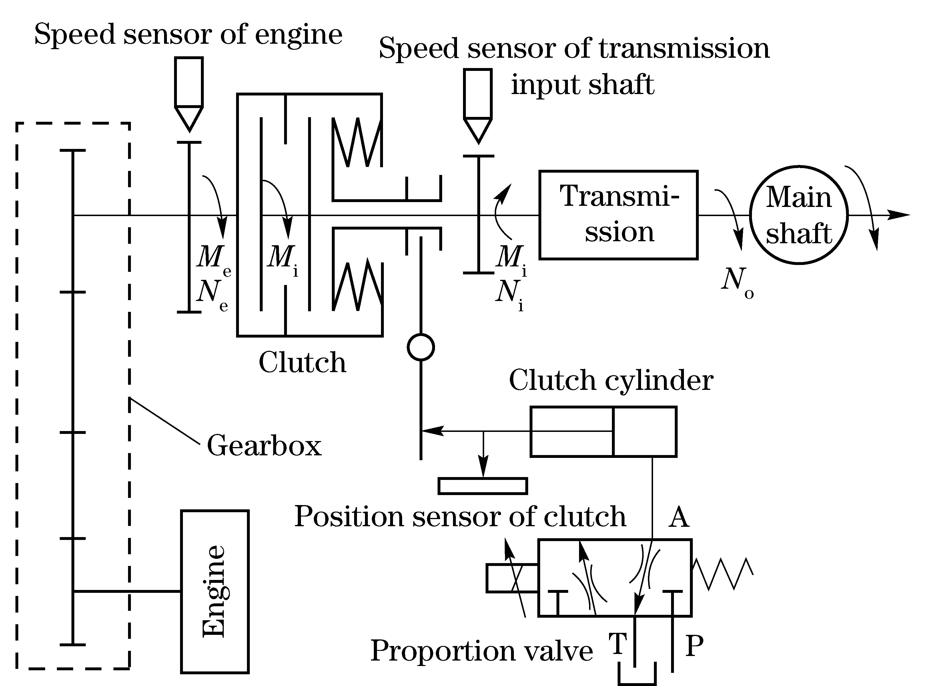
Fig.1 Principle of automated clutch system
Control component of the automated clutch system is the electro-hydraulic proportion valve. The principle is shown in Fig.1. System controls the current added on the proportion valve by adjusting PWM signal. The current determines which channel opens and the size of opening, which determines that the clutch disengages, engages or keeps its location[8].
1.3.2 Key control characteristics
Besides the control principle, we also need to learn some key control characteristics as follows.
① Flow characteristic of the proportion valve
The spool displacement of proportion valve can be mainly divided into three parts, which are shown in Fig.1. The flow value is tested under 1 MPa pressure difference. When the current is less than 0.9 A, the oil flows from A to T. When the current is between 0.9 A and 1.1 A, the oil doesn’t flow. When the current is greater than 1.1 A, the oil flows from P to A. The moving speed of the clutch is very slow when the displacement of valve is near to the second part. In the progress of slow driving, the speed of clutch disengaging or engaging should be slow, which means that the displacement of the proportion valve should be close to the second part.
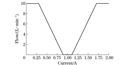
Fig.2 Flow characteristic curve of proportion valve
②Half engagement point of the clutch
Clutch’s half engagement point affects control quality of the first stage[9]. Since the test vehicle has no torque signal, the half engagement point can’t be decided precisely. The clutch control strategy is based on rotational speed signal[10]. When the output shaft speed of the clutch is higher than zero, the engagement point can be regarded as the half engagement point.
2 Identification of the slow driving condition
A vehicle driving slowly can affect the life span of its clutch. In order to prolong the span, we should identify the slow driving condition. The conditions of entering or exiting slow driving mode should be reasonable and match a driver’s intention[11].
2.1 Influencing factors of slow driving condition
①Transmission gear: Since the speed is slow, the gear should be in the lower position.
②Ne: According to the engine characteristics, whenNeis lower than 500 r/min, it will stop working; when it is greater than 1 400 r/min, the clutch slips noticeably, shortening the clutch lifespan.
③BK: We need decide whether to disengage the clutch to prevent the engine from stopping working when BK exists.
④Clutch slipping time: If the clutch is in a slipping state for a long time, its temperature will rise, so we should control the slipping time.
⑤Road condition: Sometimes we also need to go slowly on the slope, when accelerator is larger than on the even road. The engine speed may be very high, so we need to set a special condition.
2.2 Conditions of entering and exiting the slow driving mode
According to the former analysis of the influencing factors, conditions of entering and exiting the slow driving mode are acquired.
Conditions of entering the slow driving mode are as follows:
①Neis less than 1 000 r/min when the BK disappears.
②Transmission is in the first gear or reverse gear.
③Setting a switch as forced condition for the special conditions.
The vehicle must enter the slow driving function when the third condition is satisfied; if not, taking into account the first and second condition.
Conditions of exiting the slow driving mode are as follows:
①Transmission is not in the first gear or reverse gear.
②Neis greater than 1 400 r/min.
③Duration of the BK is greater than the set value (it is 20 s according to our experience).
④Slipping time exceeds the set value (it is 20 s according to our experience).
The vehicle exits slow driving function when any of the four conditions aforesaid is satisfied.
3 Fuzzy control strategy
Nowadays, the clutch control algorithm commonly used includes: fuzzy algorithm, PID algorithm, neural network algorithm and intelligent algorithm. Compared to other control algorithms, fuzzy control algorithm reflects the driver’s intention, has a high computing speed and a better real-time performance[12-16]. Compared to the traditional control algorithms, fuzzy control algorithm has a higher response speed and a lower error. So it is adopted in this paper.
3.1 Selection of control parameters and fuzzy rules
Proper control parameters are essential for the fuzzy control algorithm. They should be closely related to the powertrain.Neis related to the accelerator position, which stands for the driving intention.Niis related to the vehicle speed, whileNe-Nistands for the slipping degree of the clutch.Lcdis related to the clutch engagement degree, which stands for the torque the clutch transmits. Finally, fuzzy control parameters are as follows: error signale(Ni) and error signale(Lcd), where:e(Ni)=Ni-Ne/2,e(Lcd)=Lcd-Lhcd,Lhcdis the half engagement point of the clutch. Fuzzy inference of the clutch moving speed (v) is shown in Fig.3.
Fuzzy collection ofe(Ni) is as follows: NB, NM, NS, Z, PS, PM, PB. Fuzzy collection ofe(Lcd) is as follows: NB, NS, Z, PS, PB. Fuzzy collection ofvis as follows: NQ, NM, NS, Z, PS, PM, PQ. Triangular membership function has a better real-time characteristic in the actual control. Membership function ofe(Ni),e(Lcd) andvare shown in Fig.4.
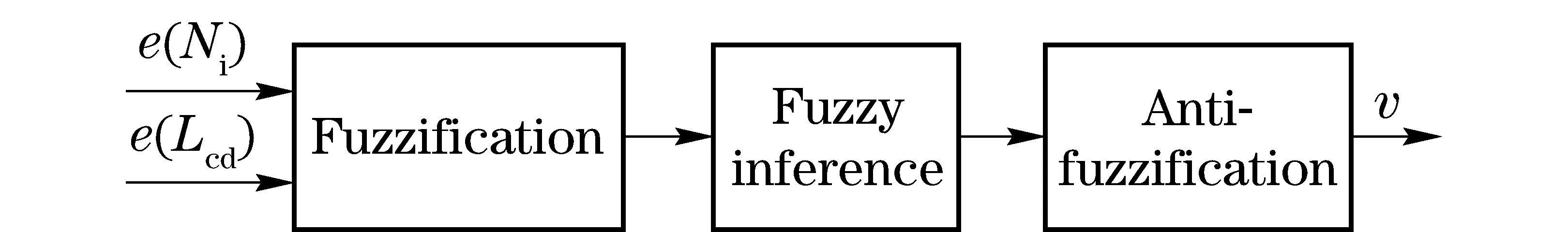
Fig.3 Fuzzy inference of the clutch control
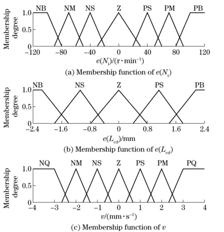
Fig.4 Membership function of fuzzy control parameters
Comfort performance of the vehicle should be taken into consideration when making fuzzy rules. Fuzzy rules of clutch moving speed are shown in Tab.1 (blank parts are considered to be unlikely to happen).
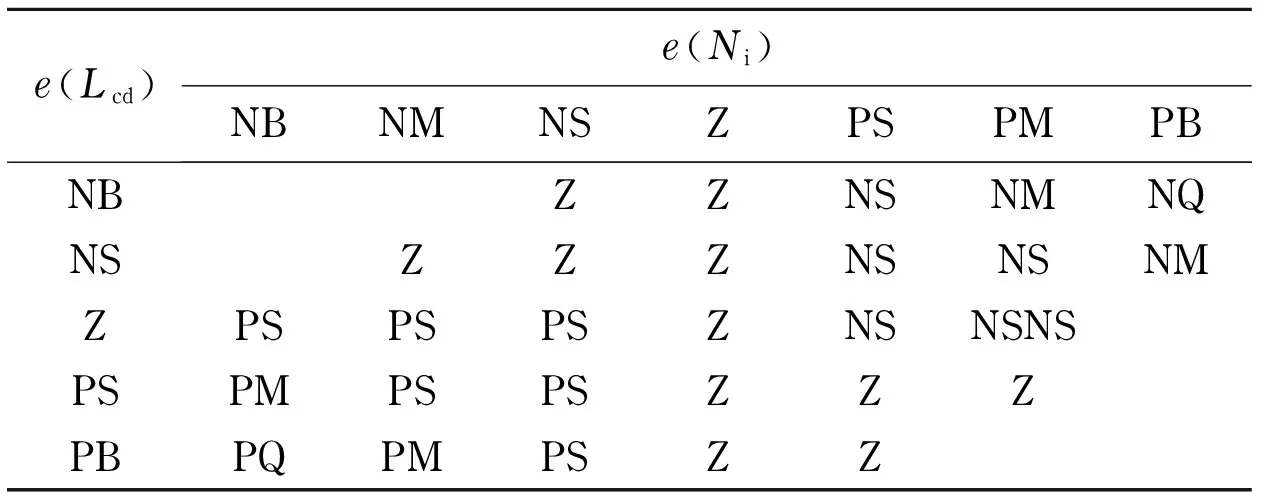
Tab.1 Fuzzy control rules of clutch’s moving speed
3.2 Fuzzy control strategy
According to fuzzy control rules, flow diagram of slow driving function is developed. Flow diagram is divided into starting stage and speed adjusting stage. In the first stage, the vehicle speed increases from zero to target speed and the engaging speed of clutch must be controlled well to ensure that the vehicle starts stably and quickly. In the second stage, the clutch should be engaged or disengaged to keep speed stable. The main control program is show in Fig.5.

Fig.5 Flow diagram of the slow driving function
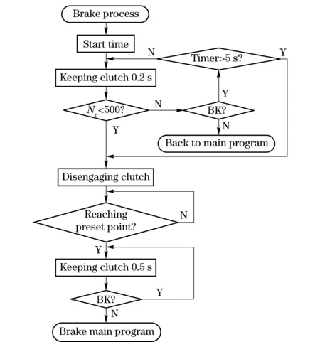
Fig.6 Flow diagram of the braking
The vehicle needs brake when its speed is too high or it is in the emergency situations. When it has a short brake, the clutch can keep its position. The clutch should be disengaged whenNeis less than 500 r/min. Sometimes the transmission control unit (TCU) disengages clutch to prolong its lifespan, ifNeis very high when BK exists. The brake control process is shown in Fig.6.
4 Vehicle test
According to slow control strategy, new software is designed in C language. Firstly, we have a slow driving test in original system. Secondly, we write the new software into TCU, and have the same test under no accelerator signal and having accelerator signal. Finally, we analyze and compare the test data.
4.1 Test in original system
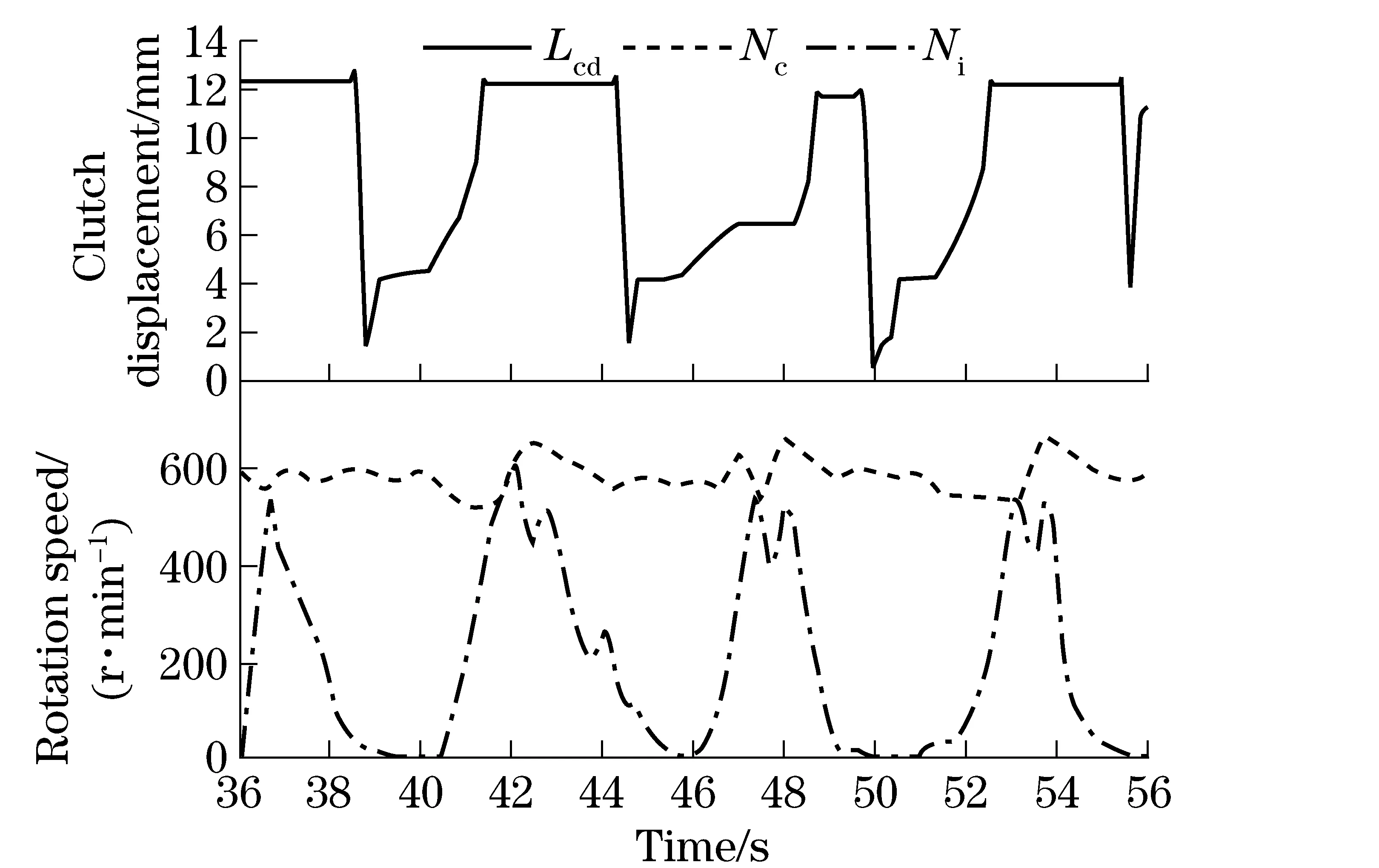
Fig.7 Data of the original system
To ensure a low speed, the driver needs to start and stop vehicle frequently. So the driver is easily to be tired and the vehicle speed varies frequently. Data analysis is shown in Fig.7. From Fig.7, the average speed ofNiis half ofNe, but the ranges ofNiandLcdare large.
4.2 Test in new system
4.2.1 No accelerator signal
There is no accelerator signal and no brake signal during the test. Data analysis is shown in Fig.8. From Fig.8, the average speed ofNiis also the half ofNe. The ranges of vehicle speed andLcdare small. When the vehicle speed exceeds target speed too much, the TCU disengages clutch. On the contrary, the TCU engages clutch. Finally, the TCU disengages clutch completely.
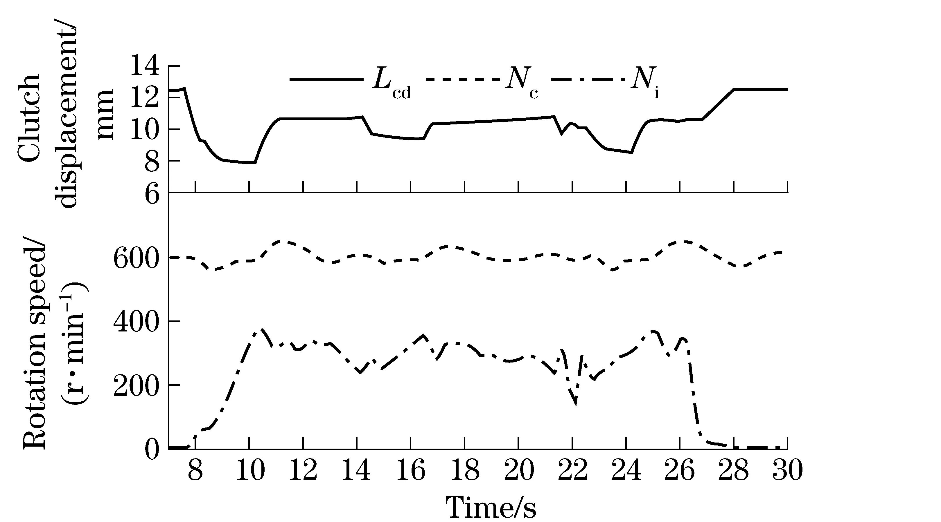
Fig.8 Case of no accelerator signal
4.2.2 Having accelerator signal
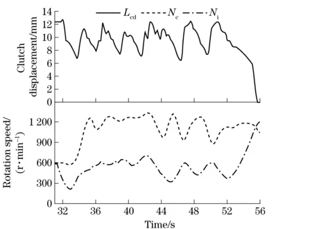
Fig.9 Case of having accelerator signal
There is an accelerator signal during the test. The data analysis is shown in Fig.9. From Fig.9, the average speed ofNiis also half ofNe, but the vehicle speed is obviously higher than in case of no accelerator signal one. The vehicle speed is half of the one when vehicle is in normal mode. WhenNiexceeds target speed too much, the TCU disengages clutch. On the contrary, the TCU engages clutch. Finally, clutch engages completely.
Above all, new program has a better effect thanthe original system. The ranges of vehicle speed andLcdare smaller than before.
5 Conclusion
Aiming at a tracked vehicle equipped with AMT, a slow driving control method is developed in this paper. The principle and requirement of the method are analyzed. The control strategy is developed based on the fuzzy algorithm. The drivers are satisfied with the new added slow driving function. The vehicle speed is low enough and the vehicle is easier to operate, which meet the drivers’ requirement. The experimental results prove that the control software has a better performance than the old one. Compared to the original system, clutch control with our method is more stable and new system reduces the burden of driver’s operation.
[1] He Zhongbo, Chen Huiyan, Xi Junqiang, et al. The control strategy and experimental research of AMT vehicle’s clutch in crawling driving condition [J]. Automotive Engineering,2003,25(6):574-577. (in Chinese)
[2] Chongqing Changan Automobile. Crawling function control method of AMT transmission :China, 102141141A [P]. 2011-08-03. (in Chinese)
[3] Wang Hongliang, Liu Haiou, Wang Juan. Strategy to control crawling vehicles with automated mechanical transmission [J]. Journal of Beijing Institute of Technology, 2013,22(2):197-201.
[4] Yu Mengjin. Research on integrated control strategy for clutch of heavy-duty commercial vehicle with AMT during starting [D]. Chongqing: Chongqing University, 2009.(in Chinese)
[5] Zhang Hui. Research and development of hydraulic actuator for the heavy vehicle with AMT [D]. Chongqing: Chongqing University, 2007.(in Chinese)
[6] Shen Fusong. Study and develop on hydraulic actuator for automatic clutch of AMT vehicle [D]. Chongqing: Chongqing University, 2011. (in Chinese)
[7] Cao Guijun. Research of integrated control of AMT power train system [D]. Changchun: Jilin University, 2004. (in Chinese)
[8] Wang Hongliang, Liu Haiou, Zhao Xijun, et al. A study on AMT clutch refitted with automatic operation mechanism based on proportional valve [J]. Automotive Engineering, 2011,33(1):47-51.(in Chinese)
[9] Sun Dongye, Qin Datong. Compensation control of clutch starting based on environment variation [J]. Transactions of the Chinese Society for Agricultural Machinery, 2005,36(3):8-11.(in Chinese)
[10] Liu Haiou, Chen Huiyan, Jin Yaying, et al. Main clutch control strategy based on speed signal for caterpillar vehicles [J]. Transactions of the Chinese Society for Agricultural Machinery, 2005, 36(6):8-11. (in Chinese)
[11] Dai Feng, Zhang Jianwu, Lu Tongli. The study of driver’s starting intentions [C]∥2011 Second International Conference on Mechanic Automation and Control Engineering, Hohhot, China, 2011.
[12] Chen Ran, Mi Lin, Tan Wei, et al. Adaptive fuzzy sliding mode controller for electro-mechanical clutch actuator of automated manual transmission vehicle[J]. Information-An International Interdisciplinary Journal, 2012, 15(11A):4715-4724.
[13] Tanaka H, Wada H. Fuzzy control of clutch engagement for automated manual transmission [J]. Vehicle System Dynamics, 1995, 24(4-5):365-376.
[14] Kong Huifang, Yan Gang. Study on fuzzy control technology for starting process of AMT clutch [C]∥2009 International Forum on Information Technology and Applications (IFITA), Chengdu, 2009.
[15] Yang Jingjing, Mi Lin, Tan Wei, et al. Engagement control study on clutch of commercial vehicle with AMT during staring based on bi-fuzzy control technology[J]. Journal of Chongqing University of Technology: Natural Science, 2012, 26(9):14-19. (in Chinese)
[16] Sun Zengqi, Deng Zhidong, Zhang Zaixing. Intelligent control theory and technology[M]. 2nd. Beijing: Publishing House of Tsinghua University, 2011. (in Chinese)
(Edited by Cai Jianying)
10.15918/j.jbit1004-0579.201524.0309
TP 463.212 Document code: A Article ID: 1004- 0579(2015)03- 0341- 07
Received 2013- 12- 13
Supported by the National Natural Science Foundation of China(51375053)
E-mail: jinhui@bit.edu.cn
猜你喜欢
杂志排行

Journal of Beijing Institute of Technology的其它文章
- Anti-hypertensive effects of rosiglitazone on renovascular hypertensive rats: role of oxidative stress and lipid metabolism
- On a novel non-smooth output feedback controller for the attitude control of a small float satellite antenna
- New model reference adaptive control with input constraints
- Facial expression recognition with contextualized histograms
- Length estimation of extended targets based on bistatic high resolution range profile
- Joint receiving mechanism based on blind equalization with variable step size for M-QAM modulation