Flow field simulation of supercritical carbon dioxide jet: Comparison and sensitivity analysis*
2015-04-20WANGHaizhu王海柱LIGensheng李根生TIANShouceng田守嶒CHENGYuxiong程宇雄HEZhenguo贺振国YUShuijie于水杰
WANG Hai-zhu (王海柱), LI Gen-sheng (李根生), TIAN Shou-ceng (田守嶒),CHENG Yu-xiong (程宇雄), HE Zhen-guo (贺振国), YU Shui-jie (于水杰)
1. State Key Laboratory of Petroleum Resources and Prospecting, China University of Petroleum (Beijing),Beijing 102200, China, E-mail: whz0001@126.com 2. Sinopec International Petroleum Exploration and Production Corporation, Beijing 100029, China
Introduction
During previous decades, the high-pressure water jet technology plays an important role in the oil and gas well drilling and the fracturing stimulations[1,2].Meanwhile, with the rapid development of the oil and gas exploitation, in the petroleum industry, the unconventional oil and gas exploration starts to attract attentions[3]. However, the operating risks and costs of the unconventional oil and gas exploration are high, while not much improvement of the water jet technology can be made. In this context, the supercritical carbon dioxide (SC-CO2) jet technology was proposed[4]. The unique properties of the SC-CO2fluid, such as the adjustable density, the low viscosity and the high diffusivity, bring about many advantages for the SC-CO2jet to be applied in the oil and gas exploration[5].
Firstly, the threshold pressure of the SC-CO2jet is far smaller than that of the water jet. The experiment results indicate that the threshold pressure of the CO2jet is 2/3 of that of the water jet for the granite and less than half of that of the water jet for the shale[6-8]. Secondly, because there is no solid particle or water in the SC-CO2fluid, the SC-CO2flooding in oil and gas reservoirs makes no damage to the reservoirs, while increasing the porosity and the permeability of the pay zone, enlarging the fluidity of the crude oil, and enhancing the reservoir energy[9]. Furthermore,since the adsorption capacity of CO2with respect to the reservoir rocks is stronger than that of CH4, CO2would replace the adsorbed shale-gas and the coal bed methane, enhancing the single well production and the oil and gas recovery[10].
Experimental results show that the rock-breakingcapacity of the SC-CO2jet is much better than that of the water jet[6]. However its mechanism remains not very clear. Meanwhile, the influences of various parameters on the flow field of the SC-CO2jet also remain to be explored. In this paper, the flow fields of the SCCO2jet are simulated using the computational fluid dynamics (CFD) method. The pressure and velocity fields of the SC-CO2jet are compared with those of the water jet. The influences of several parameters on the flow field of the SC-CO2jet are studied as well.These results provide a theoretical basis for the application of the SC-CO2jet in the oil and gas well drilling and the fracturing stimulation.
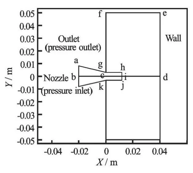
Fig.1 Geometric model of the flow field
1. CFD model
1.1 Flow field
As shown in Fig.1, a two-dimensional geometric model of the SC-CO2jet flow field is built for the simulation, where the cylindrical polar coordinate system is used. The model consists of two parts: the internal space of the nozzle (including the conical section and the cylinder section), and the jet region. This model is symmetrical vertically with respect to the nozzle axis (bd). According to the literature about the conical nozzle for the water jet[11,12], the structure parameters of the conical nozzle for the SC-CO2jet are chosen. The length parameters are as follows: the diameter of the nozzle inlet (a1) is 0.016 m, the diameter of the nozzle outlet (hj) is 0.006 m, the length of the conical section (bc) is 0.020 m, the length of the cylinder (ci) is 0.012 m, the standoff distance (id) is 0.028 m, and the height of the flow field (me) is 0.100 m.
In the SC-CO2jet, SC-CO2flows through the nozzle inlet (a1), enters the jet region, impacts on the wall (me), and then flows out of the flow field through the outlet (fg) and (kn). The nozzle inlet (a1) is defined as the pressure inlet boundary, while the flow field outlets (fg) and (kn) are defined as the pressure outlet boundary, with the pressure called the confining pressure. Other boundaries (fe, em, nm) are defined as no-slip wall boundaries.
1.2 Model details
The SC-CO2jet fracturing involves the heat transfer and the compressible fluid, therefore, the energy equations, as well as the mass equations and the momentum equations, should be considered. As the SCCO2jet is a turbulent flow of the high-speed CO2fluid,the gravity is ignored, and the standardk-εmodel is adopted for the turbulence closure. The governing equations are as follows[13]:
The mass equations are

whereρis the density,vis the velocity vector.
In the cylindrical polar coordinate system, the momentum equations take the form
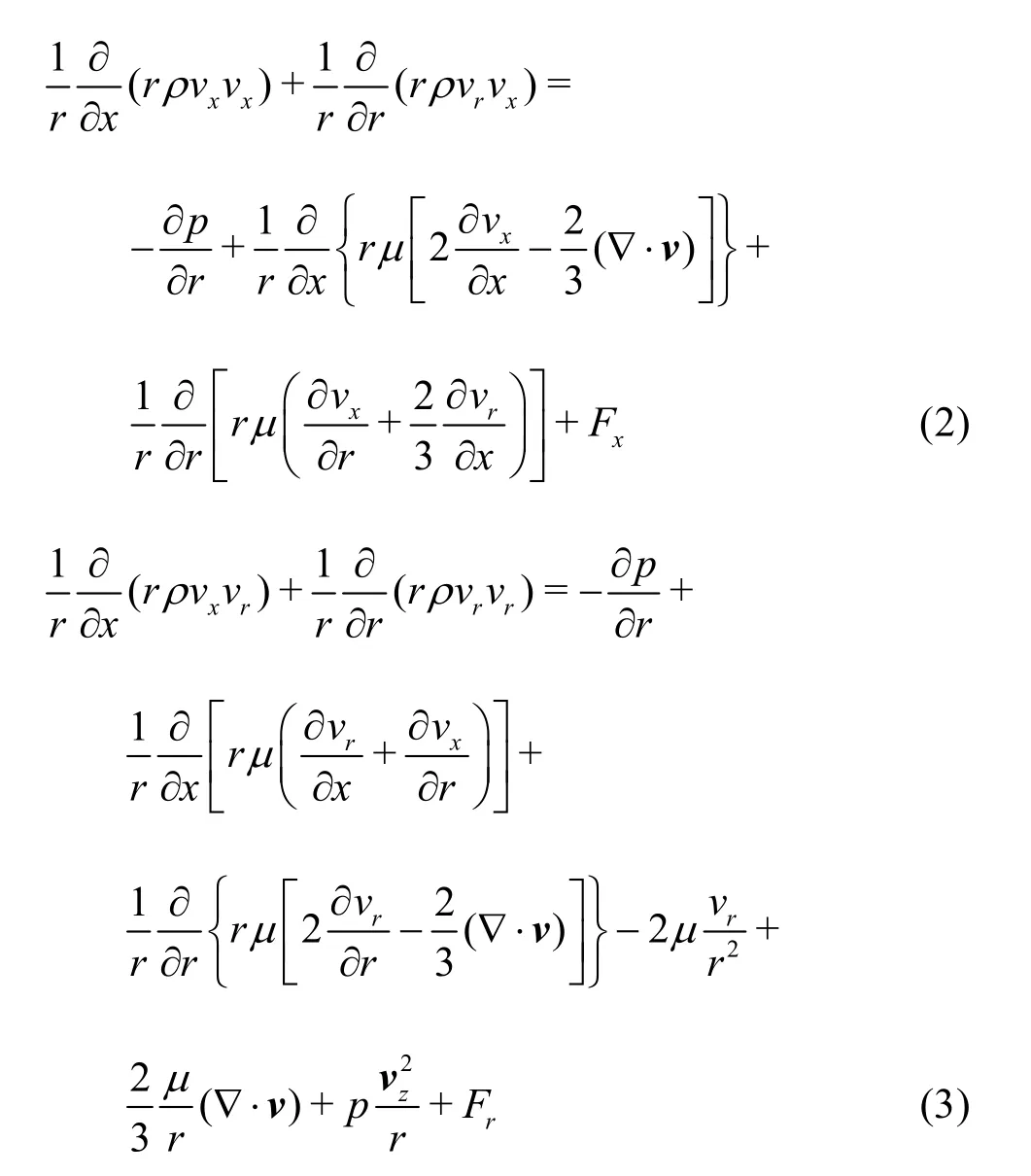
wherexis the axial coordinate,ris the radial coordinate,vxis the axial velocity,vris the radial velocity,vzis the swirl velocity,μis the dynamic viscosity,pis the pressure,FxandFrare the components of the body force.
The energy equations are

whereCpis the isobaric specific heat,Tis the temperature,kis the heat transfer coefficient,STis the viscous dissipation term.
2. The comparison of flow fields between sc-co2 jet and water jet
2.1 Conversion between velocity and pressure
The velocities and the pressures along the axis are compared between the SC-CO2jet and the water jet. As shown in Fig.2, wherevmeans the fluid velocity,Dmeans the distance to the nozzle outlet along theZaxis, when SC-CO2and water flow through the conical section of the nozzle, the fluid velocity increases gradually while the pressure decreases,indicating that the pressure energy is converted into the kinetic energy. After SC-CO2and water enter the cylinder section of the nozzle, the pressure and the velocity remain constant, indicating that no conversion happens between the pressure energy and the kinetic energy. When SC-CO2enters the jet region and impacts on the wall, the velocity decreases sharply while the pressure increases, indicating that the kinetic energy is converted into the pressure energy. Finally, the velocity becomes zero and the pressure increases to a value, slightly lower than the nozzle inlet pressure.The results indicate that like the water jet, the velocity and the pressure of the SC-CO2jet could be converted to each other.
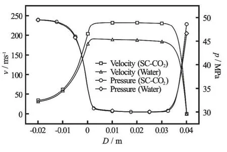
Fig.2 Velocity and pressure curves of the two jets
According to the fluid mechanics theory, the impact pressure on the wall of the high-speed fluid is

2.2 Comparison of pressure field
As shown in Fig.3, for three different nozzle pressure drops (10 MPa, 20 MPa, 30 MPa), the axial pressures of the two jets are substantially consistent. The main difference is that the axial pressures of the SCCO2jet are slightly higher than those of the water jet at the right end, indicating that the SC-CO2jet has a stronger impact pressure than the water jet. This can partly explain why the SC-CO2jet has a smaller threshold pressure and a stronger rock-breaking capacity than the water jet. This has also to do with the fact that the penetration capability of the SC-CO2fluid is stronger because of its lower viscosity and surface tension,so the impact pressure of the SC-CO2jet can be transmitted to the micro pores and fractures easily[4]. In a word, the stronger impact pressure of the SC-CO2jet is advantageous for the rock breaking and can increase the rate of penetration of the SC-CO2jet drilling.
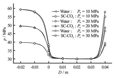
Fig.3 Axial pressure comparison of the two jets
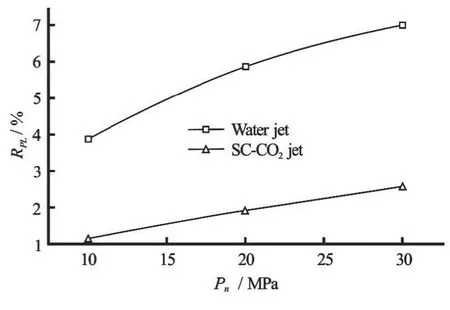
Fig.4 Comparison of pressure loss ratio
The relation between the pressure loss ratio and the nozzle pressure drop is shown in Fig.4. The pressure loss ratioRPLis defined as

wherePinis the nozzle inlet pressure. As shown in Fig.4, wherenPmeans the nozzle pressure drop, the pressure loss ratio of the SC-CO2jet is smaller than that of the water jet for the three different nozzle pressure drops. It is indicated that the SC-CO2jet has a smaller pressure energy loss than the water jet underthe same conditions. It is mainly because the viscosity of the SC-CO2is much smaller than that of the water

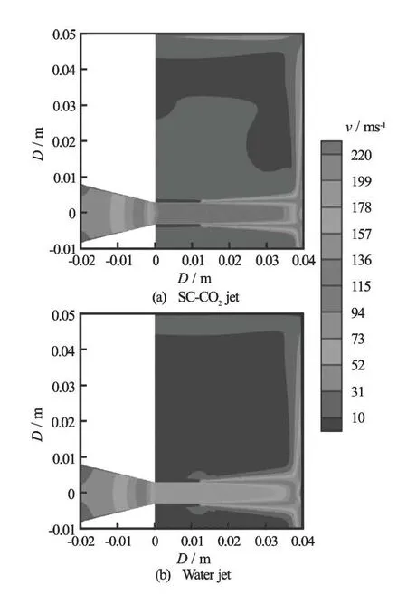
Fig.5 Velocity contours of SC-CO2 jet and water jet (m/s)
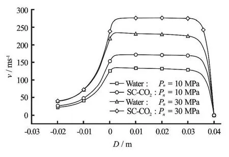
Fig.6 Axial velocity comparison of the two jets
2.3 Comparison of velocity field
As shown in Fig.5, the maximum velocity of the SC-CO2jet reaches up to 228 m/s, apparently higher than that of the water jet (163 m/s). This is because the SC-CO2jet has a higher impact pressure than the water jet under the same nozzle inlet pressure and confining pressure, as discussed previously, and the density of the SC-CO2(657 kg/m3-664 kg/m3) in the high-speed jet region is apparently smaller than that of the water (1 000 kg/m3). So according to Eq.(5), with the neglect of the influence ofPf, the maximum velocity of the SC-CO2jet is larger than that of the water jet. The results indicate that the SC-CO2jet has a higher velocity than the water jet under the same conditions, which would increase the perforation speed of the SC-CO2jet against abrasives.
The axial velocities of the two jets under the same conditions are compared as well. As shown in Fig.6, the SC-CO2jet has apparently a higher maximum velocity than the water jet for the two different nozzle pressure drops (10 MPa, 30 MPa).
3. Parameteric sensitivity analyses
3.1 Nozzle pressure drop
The nozzle pressure drop is a key parameter determining the kinetic energy of the jet and the kinetic energy of the jet directly affects the flow field[14]. So the axial pressure and the velocity of the SC-CO2jet with different nozzle pressure drops are studied. As shown in Fig.7, the maximum velocity of the SC-CO2jet increases with the increase of the nozzle pressure drop.
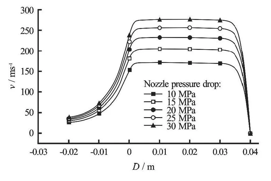
Fig.7 Influences of nozzle pressure drop on the axial velocity of SC-CO2 jet
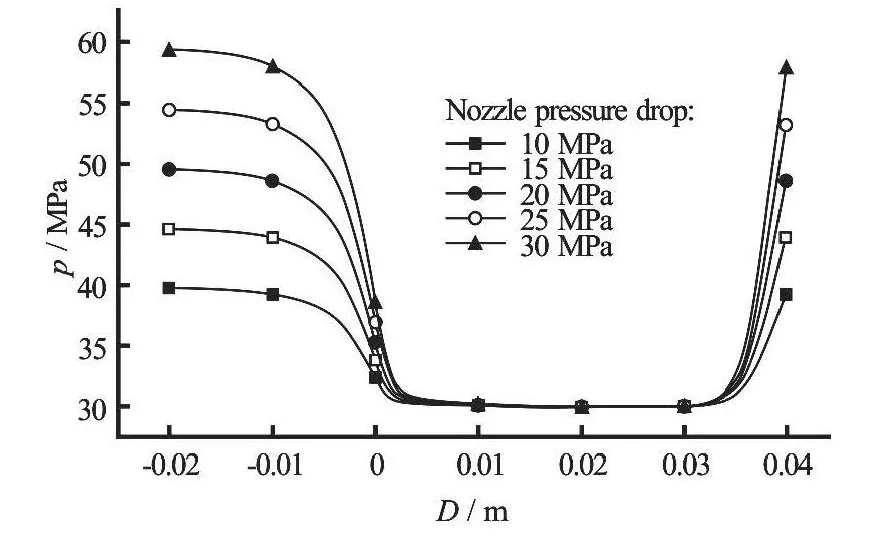
Fig.8 Influences of nozzle pressure drop on the axial pressure of SC-CO2 jet
As shown in Fig.8, the axial pressures in the nozzle cylinder section for five different nozzle pressure drops are coincided with each other, which are mainly dominated by the confining pressure (30 MPa in thesecases). When the SC-CO2fluid reaches the nozzle cylinder section, the pressure energy is converted into the kinetic energy and the axial pressures for different nozzle pressure drops are all reduced to the confining pressure. At the right end of the flow field, the impact pressure increases with the increase of the nozzle pressure drop, because the larger the nozzle pressure drop,the larger the kinetic energy and the impact pressure will be.
3.2 Confining pressure
As shown in Fig.9, whereiPmeans the impact pressure andcPmeans the confining pressure, the impact pressure increases gradually with the increase of the confining pressure, but the increment is small. The increase rate decreases with the increase of the confining pressure.
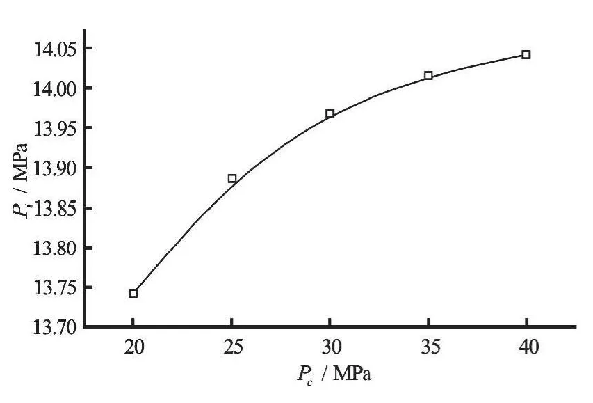
Fig.9 Influence of confining pressure on impact pressure of SCCO2 jet
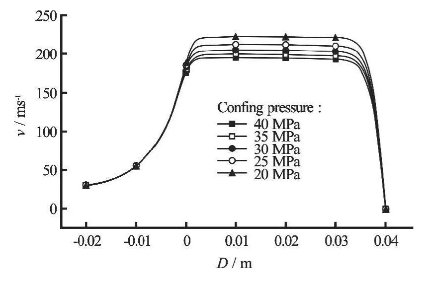
Fig.10 Influences of confining pressure on axial velocity of SCCO2 jet
The influences of the confining pressure on the axial velocity of the SC-CO2jet are shown in Fig.10.It is indicated that, for the same nozzle pressure drops and the fluid temperatures, the velocity in the highspeed jet region increases with the increase of the confining pressure.
3.3 SC-CO2 temperature
The properties of the SC-CO2fluid are sensitive to the temperature and the change of the properties can influence the structural form of the SC-CO2jet[15-18]. So the influences of the SC-CO2temperature on the axial pressure and the velocity of the SC-CO2jet are studied.
As shown in Fig.11, the axial pressure of the SCCO2jet is substantially the same when the temperature increases from 360 K to 420 K, which indicates that under the stimulation conditions of this study the pressure distributions of the SC-CO2jet are hardly affected by the temperature change. However, as shown in the enlarged drawings of the impact pressure, the impact pressure decreases slightly with the increase of the temperature. In general, the influence of the SCCO2temperature on the impact pressure could be neglected in engineering applications.
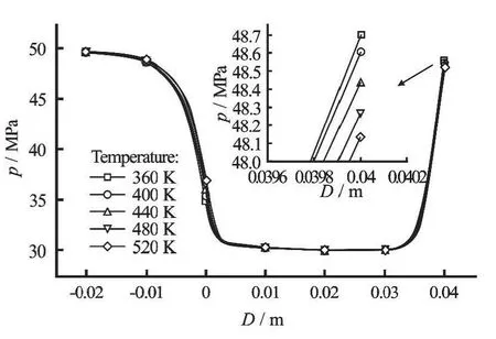
Fig.11 Influence of temperature on axial pressure of SC-CO2 jet
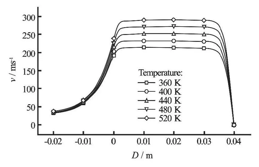
Fig.12 Influences of SC-CO2 temperature on axial velocity of SC-CO2 jet
As shown in Fig.12, the maximum velocity increases with the increase of the SC-CO2temperature.It is mainly due to the decrease of the fluid density along with the increase of the SC-CO2temperature,without considering the influence of the temperature on the impact pressure. So according to Eq.(5), ignoring the influence ofPf, the maximum velocity increases with the increase of the fluid temperature.
4. Conclusions
(1) Like the water jet, the velocity and the pre-ssure of the SC-CO2jet could be converted to each other, and the SC-CO2jet can generate a significant impact pressure on the wall.
(2) The SC-CO2jet can generate a stronger impact pressure on the wall than the water jet under the same conditions, which is advantageous for the rock breaking and can increase the rate of penetration of the SC-CO2jet drilling.
(3) The SC-CO2jet has a higher velocity than the water jet under the same conditions, which would increase the perforation speed of the SC-CO2jet against abrasives.
(4) The maximum velocity and the impact pressure of the SC-CO2jet increase with the increase of the nozzle pressure drop.
(5) In the stimulation condition of this study, the influence of the SC-CO2temperature on the impact pressure is small and can be neglected in engineering applications, while the maximum velocity of the SCCO2jet increases with the increase of the fluid temperature.
Acknowledgement
This work was supported by the Science Foundation of China University of Petroleum (Beijing) (Grant No. 2462013YJRC017).
[1] NI Hong-jian, DU Yu-kun and MA Lin et al. Study on structure optimization of self-excited pulsed jet with suck-in annulus fluids[J]. Chinese Journal of Hydrodynamics, 2011, 26(4): 487-493(in Chinese).
[2] ABDULLAH A. F. Mechanistic modeling of an underbalanced drilling operation utilizing supercritical carbon dioxide[D]. Doctoral Thesis, Baton Rouge, USA:Louisiana State University, 2007.
[3] WANG H., SHEN Z. and LI G. The development and prospect of supercritical carbon dioxide drilling[J]. Petroleum Science and Technology, 2012, 30(16): 1670-1676.
[4] WANG H., LI G. and SHEN Z. A feasibility analysis on shale gas exploitation with supercritical carbon dioxide[J]. Energy Source Part A, 2012, 34(15): 1426-1435.
[5] BI G., LI G. and SHEN Z. et al. Experimental research on the technology of hydra-jet sidetracking of radial micro-borehole[J]. Journal of Engineering Science and Technology Review, 2013, 6(5): 137-142.
[6] KOLLE J. J. Coiled-tubing drilling with supercritical carbon dioxide[C]. SPE65534. Calgary, Alberta,Canada, 2000.
[7] GUPTA A. P., GUPTA A. and LANGLINAIS J. Feasibility of supercritical carbon dioxide as a drilling fluid for deep underbalanced drilling operation[C].SPE96992. Dallas, Texas, USA, 2005.
[8] WANG Rui-he, HUO Hong-jun and SONG Hui-fang et al. An experimental study of bottom hole temperature and pressure distribution of SC-CO2jet[C]. Asia-Pacific Power and Energy Engineering Conference.Shanghai, China, 2012.
[9] WANG Zai-ming. Feature research of supercritical carbon dioxide drilling fluid[D]. Doctoral Thesis,Qingdao, China: China University of Petroleum (East China), 2008(in Chinese).
[10] SHEN Z., WANG H. and LI G. Feasibility analysis of coiled tubing drilling with super critical carbon dioxide[J]. Petroleum Exploration and Development, 2010,37(6): 743-747.
[11] QU H., LI G. and HUANG Z. et al. The boosting mechanism and effects in cavity during hydrajet fracturing process[J]. Petroleum Science and Technology. 2010,28(13): 1345-1350.
[12] HUANG Zhong-hua, XIE Ya. Research on structure parameters of conical nozzle[J]. Journal of Machine Design, 2011, 28(12): 62-65(in Chinese).
[13] SPAN R., WAGNER W. A new equation of state for carbon dioxide covering the fluid region from the triplepoint temperature to 1100 K at pressures up to 800 MPa[J]. Journal of Physical and Chemical Reference Data, 1999, 25(6): 1509-1596.
[14] NIU Ji-lei, LI Gens-heng and SONG Jian et al. An experimental study on abrasive water jet perforation parameters[J]. Petroleum Drilling Techniques, 2003, 31(2):14-16(in Chinese).
[15] HAN Bu-xing. Supercritical fluid science and technology[M]. Beijing, China: China Petrochemical Press,2005(in Chinese).
[16] CHENG Y., LI G. and WANG H. et al. Pressure boosting effect in perforation cavity during supercritical carbon dioxide jet fracturing[J]. Atomization and Spray, 2013, 23(5): 463-474.
[17] DU Yu-kun, WANG Rui-he and NI Hong-jian et al.Rock-breaking experiment with supercritical carbon dioxide jet[J]. Journal of China University of Petroleum (East China), 2012, 36(4): 93-96(in Chinese).
[18] GUPTA A. Feasibility of supercritical carbon dioxide as a drilling fluid for deep underbalanced drilling operations[D]. Master Thesis, Baton Rouge, USA: Louisiana State University, 2006.
猜你喜欢
杂志排行
水动力学研究与进展 B辑的其它文章
- A general framework for verification and validation of large eddy simulations*
- Direct calculation method of roll damping based on three-dimensional CFD approach*
- Visualization study on fluid distribution and end effects in core flow experiments with low-field mri method*
- Large-eddy simulation of the flow past both finite and infinite circular cylinders at Re =3900*
- Safe operation of inverted siphon during ice period*
- Ship hull optimization based on wave resistance using wavelet method*
