The Study of the Varying Characteristics of Cathodic Regions for Defective Coating in 3.5% Sodium Chloride Solution by EIS and WBE
2015-04-05WANGHaijieWANGJiaWANGWeiandZHANGWei
WANG Haijie, WANG Jia,, WANG Wei, and ZHANG Wei
1)College of Chemistry and Chemical Engineering,Ocean University of China,Qingdao266011,P.R.China
2)State Key Laboratory for Corrosion and Protection of Metals,Shenyang110016,P.R.China
3)Qingdao Marine Corrosion Institute,Central Research Institute for Steel and Iron,Qingdao266071,P.R.China
The Study of the Varying Characteristics of Cathodic Regions for Defective Coating in 3.5% Sodium Chloride Solution by EIS and WBE
WANG Haijie1), WANG Jia1),2),*, WANG Wei1), and ZHANG Wei3)
1)College of Chemistry and Chemical Engineering,Ocean University of China,Qingdao266011,P.R.China
2)State Key Laboratory for Corrosion and Protection of Metals,Shenyang110016,P.R.China
3)Qingdao Marine Corrosion Institute,Central Research Institute for Steel and Iron,Qingdao266071,P.R.China
The current distributions over carbon steel under iron red alkyd primer exposed to 3.5% sodium chloride solution were mapped using the wire beam electrode (WBE). The electrochemical impedance spectroscopy (EIS) of the WBE was carried out to analyze the performance of coating delamination and corrosion behavior of carbon steel beneath defective coating. The EIS data revealed that protective capability of coating decreased with immersion time and the degree of cathodic delamination showed a rapid rise. The current density distribution of WBE indicated that cathodic sites was located at the defect at the beginning of immersion and gradually spread into the intact coating. The cathodic regions were distinguished from the anodic area and distributed over the WBE. The changes of cathodic sites could reflect the deterioration process of defective coating. The cathodic area ratio was a more useful parameter than the cathodic delamination degree to evaluate the coating cathodic delamination. The polarity reversals of electrodes at the defect and beneath coating were observed. A simple discussion of relationship between the blister and the polarity reversal was made from a standpoint of electrochemical distribution. WBE method was able to map and record the changes of local cathodic sites beneath defective coating in real time, which could provide more detailed information about the local degradation of coating.
organic coatings; defective coatings; deterioration; EIS; wire beam electrode
1 Introduction
Iron red alkyd primer is made from alkyd, iron oxide, and organic solvent. Due to the good corrosion resistance, weathering resistance and convenience, it is extensively utilized in the corrosion protection of sea-going ships, offshore drilling platforms, offshore steel structures, and so on.
However, its service life is usually limited due to the attack of corrosive materials (water molecules, oxygen, ions). Cathodic delamination is widely accepted as a failure model of organic coatings on steel substrates (Funke, 1981; Deflorian and Rossi, 2006), which usually initiates from the defect or ‘weak’ site (Hare and Fernald, 1984). The interface between metal and organic coating is chemically attacked by hydroxyl (Leidheiser, 1983, 1987) or peroxide, superoxide and hydroxyl radicals formed as intermediate products during reduction reaction of oxygen (Wroblowa and Qaderi, 1990; Wroblowa, 1992; Gervasioet al., 1998, SØrensenet al., 2010a, 2010b). All these mechanisms reveal that cathodic site plays a sig-nificant role in the failure process of organic coating. Therefore, it is essential for coated steel to investigate the variation of cathodic areas and have a better understanding of the fundamental processes of corrosion reactions and mechanism of cathodic delamination from the view of electrochemical distribution. However, to date, the dynamic changes of the cathode under organic coating during the coating deterioration process have seldom been investigated due to a lack of suitable electrochemical technique.
Admittedly, electrochemical impedance spectroscopy (EIS) is anin situ, non-destructive, rapid and convenient technique useful for evaluating the corrosion performance of coated metals subjected to aqueous environment (Wen, 2011; Dhoke and Khanna, 2012; Naderiet al., 2004). Many parameters about the coating delamination can be provided by fitting equivalent circuit. However, the response obtained by EIS represents the average information of the whole electrode surface (Doherty and Sykes, 2004; Zhang and Cao, 1998), losing the localized corrosion information associated with the corrosion reaction at defect (Donget al., 2008).
Some local electrochemical techniques have been applied to detect local electrochemical information of coated metals. The scanning Kelvin probe (SKP) tech-nique has been used to map the potential distribution of coating on steel substrates (Stratmannet al., 1996). The drawback of SKP is that it can not be used in an electrolyte solution. Scanning vibrating electrode technique (SVET) can determine the potential gradient with a scanning vibrating probe and map ionic current on coated metal surface (Zinet al., 2005). The scanning electrochemical microscopy (SECM) has been used to characterize the topography and redox activity of coated metals surface by measuring the change of current with a mobile ultramicroelectrode immersed in an electrolyte solution (Bastoset al., 2005). And the local electrochemical impedance spectroscopy (LEIS) has widely been employed in evaluating coating localized degradation and the corresponding mechanism (Zhonget al., 2008). However, in all scanning probe techniques discussed above, the probe is constantly adjusted to accommodate the tiny distance between the probe and the electrode surface, which limits their application in middle and later periods of the corrosion.
Wire beam electrode (WBE, also called multi electrode array) is a novel local electrochemical tool to study the current distribution on metal or coated metal surface (Tanet al., 2001; Zhong, 2002), which can overcome those limitations. The key feature of the WBE method is that it allows quick temporal and spatial slight current measurement on coated WBE surface, which directly reflects the behavior of coating delamination and metal corrosion underneath coating. Tan (1991) detected the electrochemical homogeneity of organic coating on metal and the distribution of coating defect by WBE. Recently, Konget al.(2012) studied the intact coating degradation process by WBE combined with EIS and found that there were different characteristics in different regions. Zhanget al.(2010) further investigated that process and discussed the degradation mechanism of the defective coating. To research into real situation of coating delamination, the dynamic distribution of cathode is necessary.
The objective of this paper is to investigate the delaminating process of the iron red alkyd primer delamination by WBE combined with EIS and the varying characteristics of cathodes from a point of current distribution. For this purpose, the degradation process of defective coating containing iron red alkyd primer in 3.5% sodium chloride solution was investigated as a function of time by combining EIS and WBE technique.
2 Experiment
2.1 The WBE Fabrication
The WBE was made from 121 identical carbon steel wires (1.6 mm diameter) and embedded in epoxy resin. The distance of each wire was 0.8 mm. Each carbon steel wire has a surface area of about 0.02 cm2, the whole area of the working surface of WBE specimen was about 2.43 cm2. The WBE was grounded with silicon carbide papers from 100-grade to 1000-grade. After washing by redistilled water, iron red alkyd primer was coated on the WBE surface and then placed in a dust shield until the coating was dry. The coating thickness was measured using a Fischer equipment with a precision, in the thickness range of the studied materials, of ±5 μm. The thickness results are the mean value of 20 measurements. The thickness of the coating is 95 μm. The defect was made by a knife and the range of the scratch was wire 59-63, as shown in Fig.1.
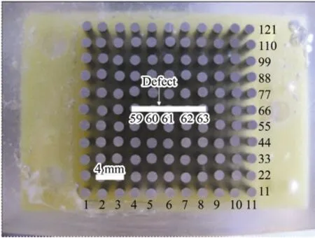
Fig.1 The top view of the WBE before coated with iron red alkyd primer.
2.2 The EIS Measurement
The EIS measurement was carried out on coated WBE in the frequency range of 105Hz to 10-3Hz at room temperature using 2263 testing system. The amplitude of sinusoidal voltage signal was 10 mV. A three-electrode cell configuration was applied to EIS measurement with saturated calomel electrode (SCE) as reference electrode and Pt sheet as a counter electrode. All the wires were coupled together and used as the working electrode. Electrolyte solution was 3.5% sodium chloridel solution composed of analytical pure grade NaCl from Jinan chemical industry institute and redistilled water. The EIS test software was PowerSuit software and EIS data were analyzed by ZView2 software.
2.3 The Current Distribution Measurement
The WBE test device was developed in our lab, which was made of modular instruments (National Instruments Co. NI) (Wanget al., 2009). All wires in WBE were connected each other in order to make the electron flow freely. When the current measurement began, the first wire was disconnected with other wires. Other wires were still connected together. The galvanic current between each wire and other coupled wires was recorded successively. This process was controlled automatically by software with Lab VIEW 8.5. The galvanic current of each wire was measured three times. Surfer 8.0 software was used to graph the current maps.
3 Results and Discussion
3.1 Evolution of Electrochemical Impedance Spectroscopy with Immersion Time
The EIS plots of defective coating degradation in 3.5%sodium chloride solution with different time are given in Fig.2. During the early stage of immersion, there is only one single capacitive loop in the impedance diagram which is characterized by one time constant (Figs.2a and 2b). The impedance modulus is approximately 3.5×10³Ω, which is dramatically lower than that for intact coating in this stage. This is attributed to the existence of defect, in agreement with the literature (Zhonget al., 2008) . It can be fitted with the equivalent electrical circuit as shown in Fig.3a.
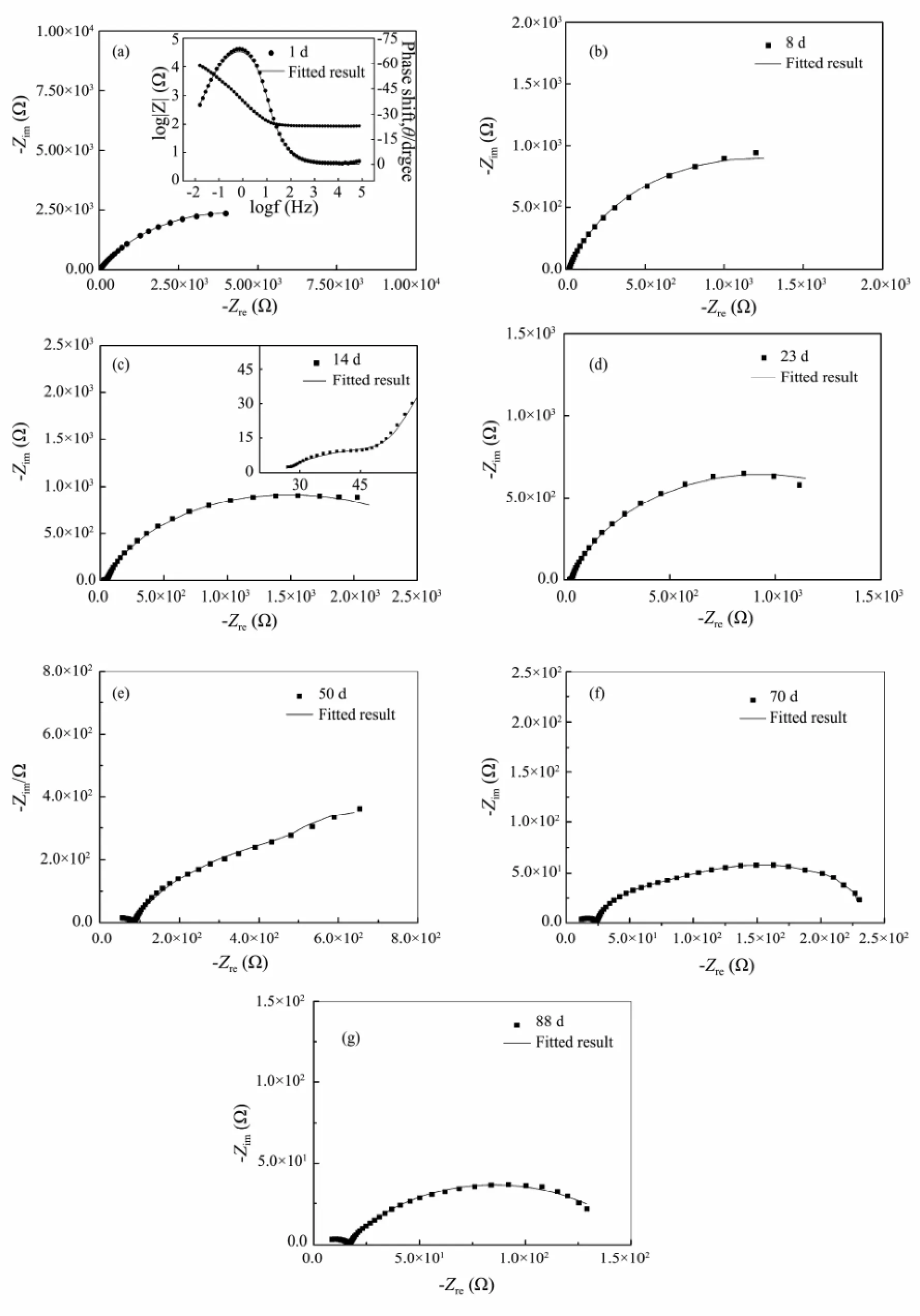
Fig.2 The EIS plots of defective coating degradation exposed in 3.5% sodium chloride solution with different time.
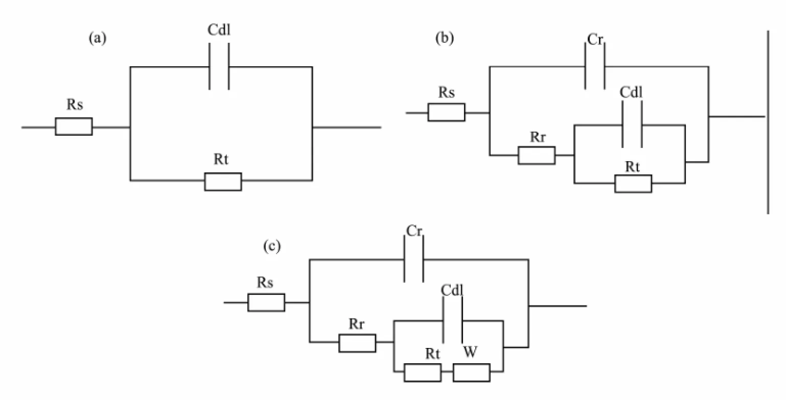
Fig.3 Equivalent circuits for the defective coating on steel substrate. Rs, resistance solution; Rr and Cr, resistance and capacitance of rust layer; Rt, the charge transfer resistance; Cdl, the electric double layer capacitance; W, Warburg diffusion.
As immersion time is prolonged, two capacitive loops are observed in Figs.2c and 2d, showing the characteristic of two time constants. The high-frequency loop reflects information about the rust layer, while the low-frequency semicircle represents the metallic corrosion reaction underneath coating. After 14 d of immersion, a typical Warburg impedance character is observed at low-frequency range as shown in Fig.2e. The appearance of Warburg impedance indicates that corrosion reaction is controlled by the diffusion process (Lenget al., 1998). At this time, we can fit it with the equivalent circuit, as shown in Fig.3c. With further extension of exposure, the plots are still characterized with two capacitive loops and the radius of low-frequency loop decreases, indicating decrease of the charge transfer resistance. It can be fitted with the equivalent circuit shown in Fig.3b.
The degree of coating delamination (Ad) was chose to evaluate the coating degradation, which can be calculated from the following equation (McCluneyet al., 1992).

whereCdlois electric double layer capacitance of bare steel before coated with iron red alkyd primer (= 19972 μF), andCdlis that of coated steel. Fig.4 presents the degree of coating delaminationAdas a function of immersion time. It can be seen from Fig.4 that the value ofAdis low and stable during 8 d of immersion. With increasing of immersion time, it begins to increase rapidly, indicating decrease of coating protective property.
From the above discussion, we can see that the protective property of the defective coating continuously becomes less effective and the extent of coating delamination increases. EIS responses just reflect indirectly the coating delamination by fitting equivalent circuit and can not make a prediction about the initiation and propagation of the coating delamination and the varying change of cathodes. These difficulties can be overcome by mapping current distribution of coated WBE.
3.2 The Current Distribution of Coated WBE
The current distribution maps of coated WBE over a period of 88 d are presented in Fig.5. The color calibration unit on right side of the figure is µA cm-2. A negative value represents the cathodic current, while positive one is the anodic current. It can be seen from Fig.5a that the cathode is located at wire 61 and 63, while the anodic current peaks are observed at wire 59, 60 and 62 immersed for 1 d. The current value underneath the coating around defect is almost 0 µA cm-2, which means that corrosion reaction does not happen beneath the coating. Cathode and anode appear simultaneously on electrodes at defect area. This may be due to the heterogeneity of bare steel. The maximum anodic and cathodic currents were recorded with 20 and -10 µA cm-2, respectively, indicating highly active galvanic reactions at defect region. After 8 d of immersion, two new cathodic sites formed at wire 48 and 43. The major anodic sites are still located at defect region. The anode and cathode are in close proximity.
With the extension of exposure, the anodic sites are still located at defect area, while the cathodic sites begin to expand into intact coating around defect and its number gradually increases (Fig.5c-5e). After 88 d of immersion, two new anodes are clearly observed at wire 81 and 82,while the major cathodic sites have moved to the edge of the WBE. The major cathodic sites are completely independent beneath the coating and the island-shaped anodes are surrounded by the cathodic sites. By this moment, we can see from EIS data that coating has lost its protective properties.
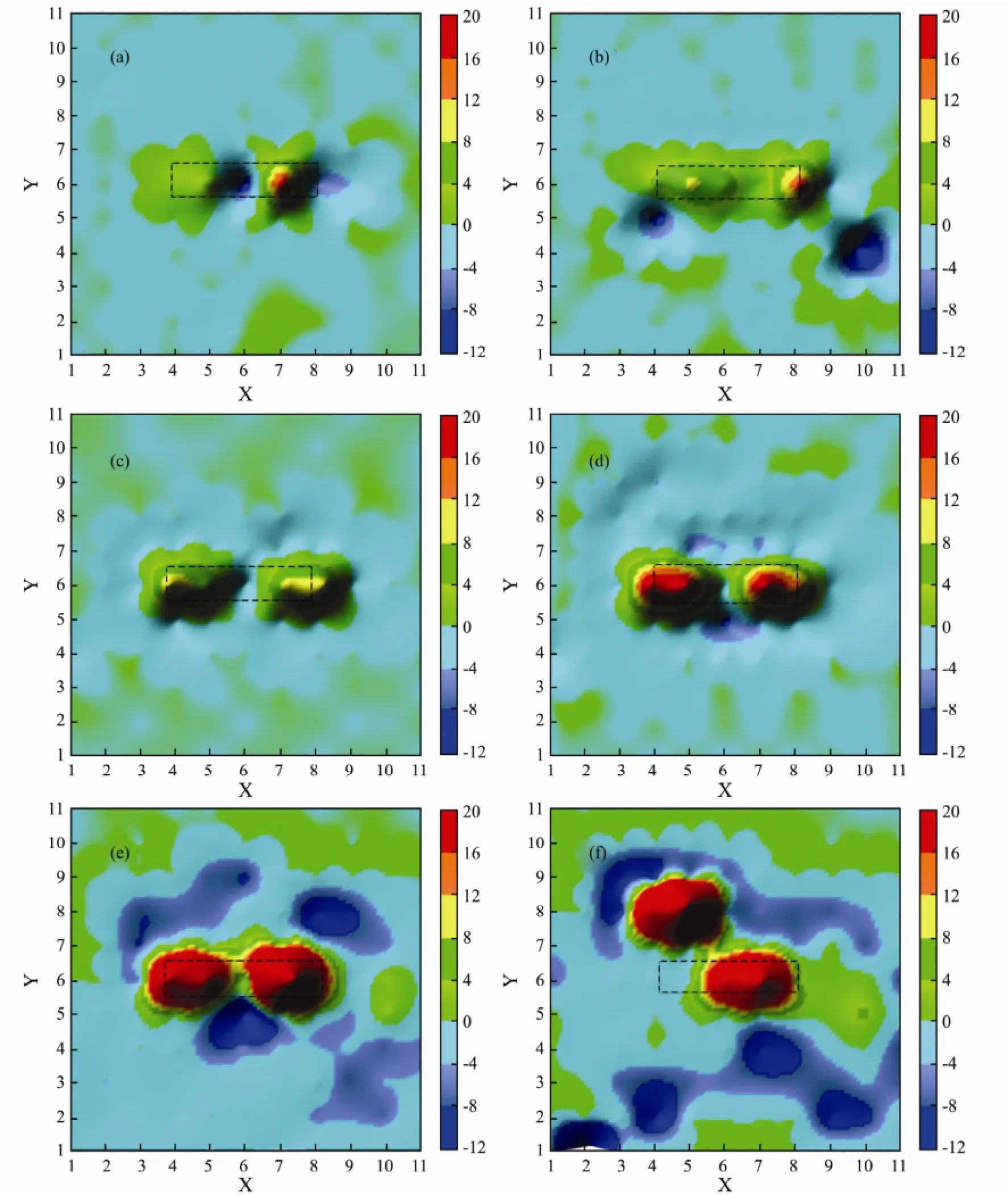
Fig.5 The current distribution maps of the WBE for defective coating degradation in 3.5% sodium chloride solution at different testing time: (a), 1 d; (b), 8 d; (c), 18 d; (d), 23 d; (e), 53 d; (f), 88 d.
Fig.6 is the current density changes with exposure time for wire 61 at defect region and wire 2, 45 and 82 beneath coating. A wire 61 is performance for a larger cathodic current during the initial 40 d. Nevertheless, as time elapses, the current value changes into positive one. This can be explained by the deposition of corrosion products. When the four electrodes (wire 59, 60, 62 and 63) at defect zone are covered by corrosion products, their anodic reactions are inhibited and the cathodic area is large. At this time, anodic dissolution reaction of wire 61 will be accelerated, resulting in polarity reversal and then exhibiting an anodic current (Zhang, 2010).
At the beginning of immersion, all the current values in wire 45, 82 and 2 are almost equal to 0 µA cm-2due to the intactness of the coating. After about 35 d, 30 d of immersion time, respectively, they have been exhibited as the feeble cathodic current for wire 82 and 2. At the end stage, the polarity reversals are also observed in wire 82 and 2. The reason for polarity reversals for them will be given in the last section. Largest anodic current value means that anodic dissolution reaction takes place drastically. After 40 d of immersion, anodic current value in wire 45 be-comes negative till the end of immersion.
Fig.7 is the dynamic trajectory changes with immersion time for major cathodic sites (Fig.7a) and cathodic area ratio (Fig.7b). The dashed part is the defect area and the symbols represent the major cathodic sites at different time as shown in Fig.7a. We could clearly see that cathodic sites are located at defect area at the beginning of immersion and the number of cathodic sites is very small. With the extension of exposure, the cathodic sites begin to spread into the intact coating around the defect. The markedly increases amount of cathodic sites, means that the degree of cathodic delamination is enhanced. That is in good agreement with Fig.4. Ultimately, the cathodic sites is distinguished from the defect zone and the cathodic sites are widely dispersed throughout the WBE surface, indicating the failure of coating.
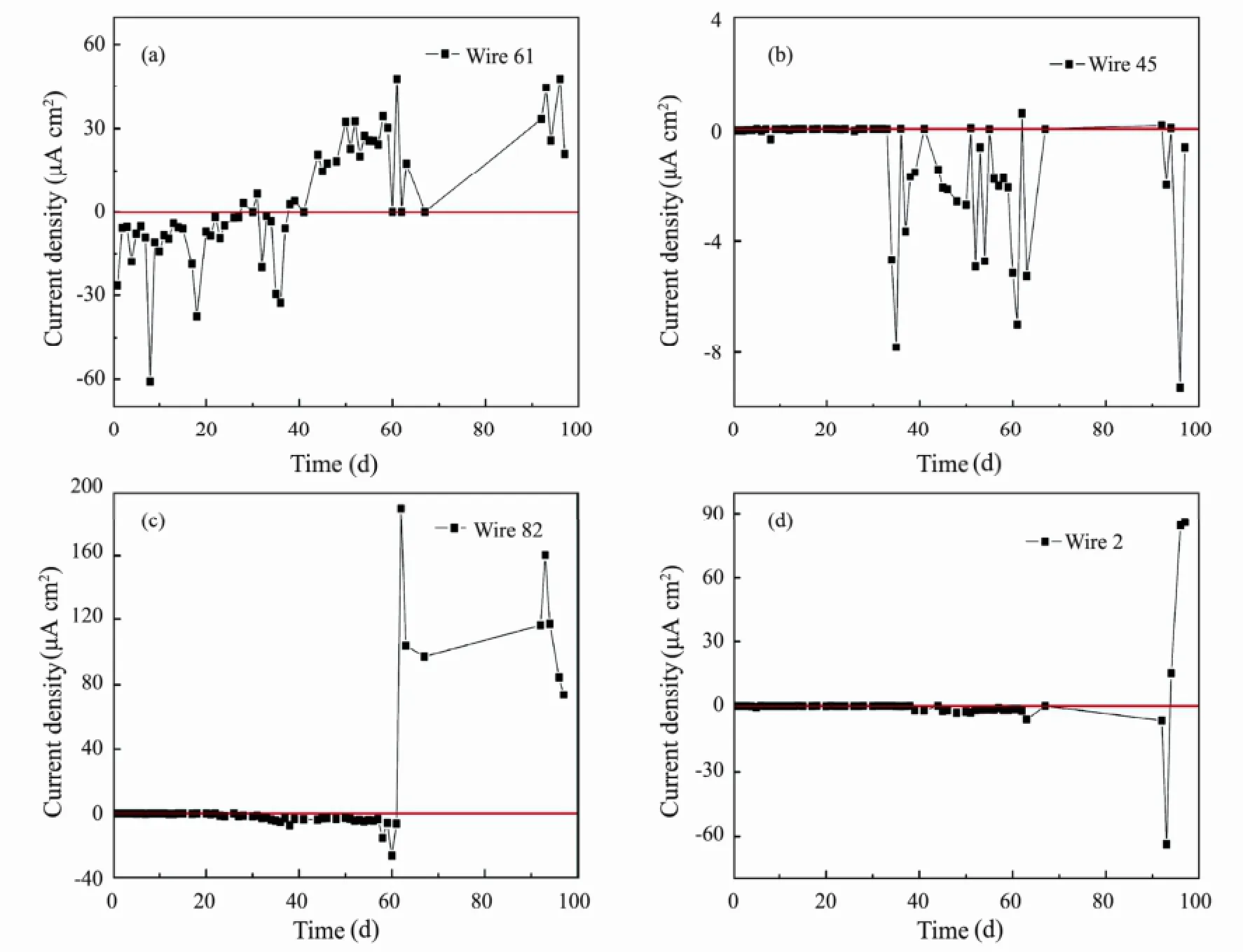
Fig.6 The current density changes with exposure days for wire 61 at the defect and wire 2, 45, and 82 beneath the coating.
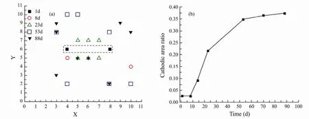
Fig.7 The trajectory changes with immersion time for the main cathodic sites and cathode area ratio.
If we think that cathodic current density |Ic| values higher than 1µA cm-2reveal a delaminated area, then, the cathodic area ratio can be calculated as Ac/Atolas shown in Fig.7b. It can be observed from Fig.7b that during the initial 8d the cathode area ratio keeps a small value and almost unchanged. As the time of immersion increases, the cathode area ratio exhibits a rapid increase in value and then shows a slow increase. It can be seen from Figs.8a-8c that the number of the blisters is almost unchanged, consistent with the trend of cathode area ratio of the last immersion stage, which indicates that cathode area ratio is a valid parameter for evaluating the coatingdelamination. We can clearly see the initiation and propagation of the coating delamination from Fig.7a and Fig.7b. Comparing Fig.7b and Fig.4, we can see that at the beginning the two curves for Adand the cathode area ratio show similar trend, but after 8d the deviation is visible in curves. We think the existence of that deviation is caused by the inaccuracy ofAd.Adis a calculated value and the value ofCdloften cannot be extracted from the experimental impedance spectra with sufficient accuracy resulting in the generation of the deviation (Mansfeld and Tsai, 1991). Cathodic area ratio is a real value which can directly reveal the localized delamination processes.
3.3 The Morphology Pictures of WBE and the Coated WBE
Morphology pictures of the coated WBE surfaces immersed for 37 d, 56 d, 90 d and WBE after removing coating are illustrated in Fig.8. It can be seen from Fig.8a-8c that the corrosion products gradually deposit at the defect region and the color changes from orange-brown to orange-black. The blisters are observed in the vicinity of this defect and the range of blisters gradually enlarges toward the edge of WBE, in agreement with analyses of Fig.5 and Fig.7. Blisters cracking are found at wire 2, 81 and 82 in Fig.8c. The polarity reversal at wire 2 and 82 can be explained by blisters cracking. When the oxygen permeates into coating, the cathodic reactions take place at wire 2 and 82. Once the blisters have cracked, the anodic dissolution reaction will take place, and then the current changes into an anodic current.
Etch pits are clearly visible on the surface of the five wires at defect and wire 2, 81, and 82, as shown in Fig.8d. It is distinctly observed that the amount of corrosion products at wire 61 electrode is less than that at other four wires at defect. We think this may be attributed to the deposition of corrosion products inhibiting the anodic dissolution reaction, consistent with the analysis results of Fig.6a. Over a period of 90 d immersion, a lot of blisters are observed on coated WBE surface, as shown in Fig.8c. Although there are many blisters, only a few of them have the phenomenon of polarity reversal in Fig.6. So we can not be sure that the polarity variation just depends on whether the blister has occurred beneath coating.
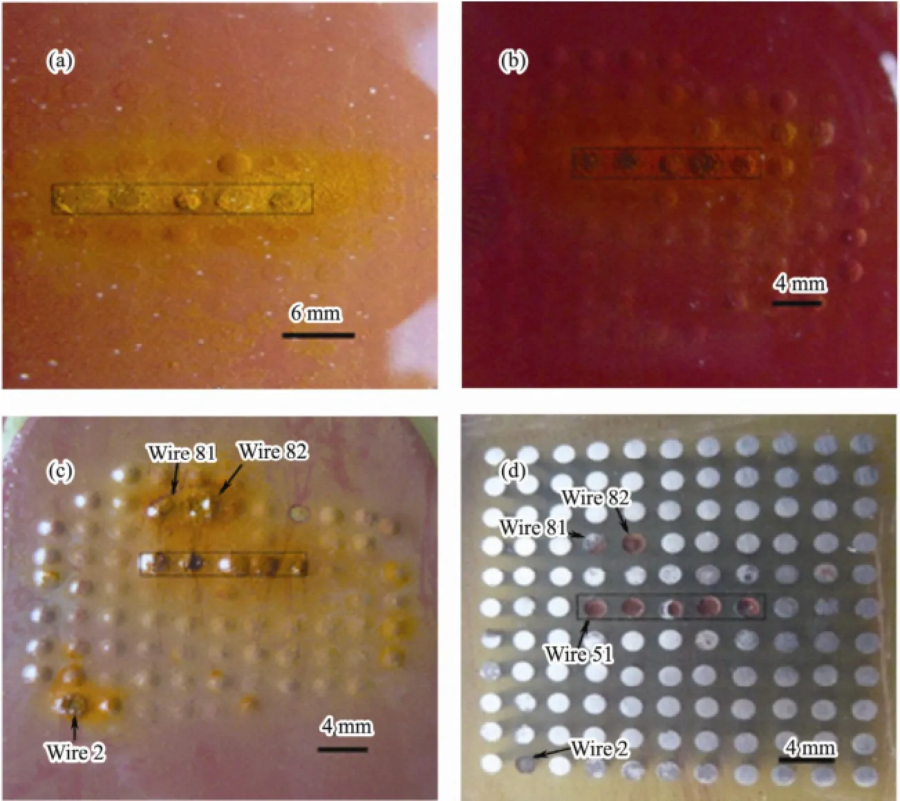
Fig.8 Morphology pictures of the coating surface immersed for different time: (a) 37 d (b) 56 d (c) 90 d and pictures of the substrate after coating is removed.
The aim of this work is only to discuss coating delamination and metal corrosion from the view of current distribution and EIS, rather than put forward some new delamination mechanism.
4 Conclusions
The delamination of iron red alkyd primer coated on carbon steel substrate was study by EIS and WBE technique. The EIS data indicated that the protective capability of coating decreased over a period of immersion. The current distribution of coated WBE revealed the variation characteristics of cathodic regions beneath coating. The cathodic sites spreading from the defect to the coating surrounding the defect imply that the coating delamination started from the defect area and spread toward intact coating around defect. At the same time, the number of cathodic sites increased gradually with immersion time. Not all the electrodes with blister occurencehave the phenomenon of polarity switching. WBE was a useful tool to investigate the delamination of coated steel with a defect. Cathodic area ratio was a valid parameter for evaluating the degree of coating delamination. WBE and EIS can be combined to obtain more and better relevant information about monitoring occurrence and development process of local coating degradation from different views.
Acknowledgements
This work was supported by the National Natural Science Foundation of China (Grant No. 51131005).
Funke, W., 1981. Blistering of paint films and filiform corrosion.Progress in Organic Coatings, 9 (1): 29-46.
Deflorian, F., and Rossi, S., 2006. An EIS study of ion diffusion through organic coatings.Electrochimica Acta, 51 (8): 1736-1744.
Hare, C. H., and Fernald, M. G., 1984. Anticorrosive barrier pigments.Modern Paint and Coatings, 74 (10): 138.
Leidheiser, H., Wang, W., and Igetoft, L., 1983. The mechanism for the cathodic delamination of organic coatings from a metal surface.Progress in Organic Coatings, 11 (1): 19-40.
Leidheiser, H., 1987. Cathodic delamination of polybutadiene from steel - A review.Journal of Adhesion Science and Technology, 1 (1): 79-98.
Wroblowa, H. S., and Qaderi, S. B., 1990. Mechanism and kinetics of oxygen reduction on steel.Journal of Electroanalytical Chemistry, 279 (1): 231-242.
Wroblowa, H. S., 1992. Intermediate products of atmospheric oxygen reduction and the integrity of metal-organic coating interface.Journal of Electroanalytical Chemistry, 339 (1):31-40.
Gervasio, D., Song, I., and Payer, J. H., 1998. Determination of the oxygen reduction products on ASTM A516 steel during cathodic protection.Journal of Applied Electrochemistry, 28 (9): 979-992.
SØrensen, P. A., Dam-Johansen, K., Weinell, C. E., and Kiil, S. O. R., 2010a. Cathodic delamination of seawater-immersed anticorrosive coatings: Mapping of parameters affecting the rate.Progress in Organic Coatings, 68 (4): 283-292.
SØrensen, P. A., Weinell, C. E., Dam, J, K., and Kiil, S. O. R., 2010b. Reduction of cathodic delamination rates of anticorrosive coatings using free radical scavengers.Journal of Coatings Technology and Research, 7 (6): 773-786.
Wen, L., Wang, Y. M., Liu, Y., Zhou, Y., Guo, L. X., Ouyang, J. H., and Jia, D. C., 2011. EIS study of a self-repairing microarc oxidation coating.Corrosion Science, 53 (2): 618-623.
Dhoke, S. K., and Khanna, A. S., 2012. Electrochemical impedance spectroscopy (EIS) study of nano-alumina modified alkyd based waterborne coatings.Progress in Organic Coatings, 74 (1): 92-99.
Naderi, R., Attar, M. M., and Moayed, M. H., 2004. EIS examination of mill scale on mild steel with polyester -epoxy powder coating.Progress in Organic Coatings, 50 (3): 162-165.
学校要转变教学观念。学校要端正办学思想,真正树立素质教育的观念,重视学生的心理健康问题,把心理健康教育真正作为素质教育的重要组成部分摆在学校教育的重要地位。建立和完善心理咨询和教育体系,坚持以学生自我调适为主,教师辅导为辅,重点医治的方针,采用多种方式方法,开展丰富多彩的活动,普及心理健康教育,从而提高学生的心理素质。
Doherty, M., and Sykes, J. M., 2004. Micro-cells beneath organic lacquers: A study using scanning Kelvin probe and scanning acoustic microscopy.Corrosion Science, 46 (5):1265-1289.
Zhang, J. Q., and Cao, C. N., 1998. Study and evaluation on organic coatings by electrochemical impedance spectroscopy.Corrosion and Protection, 19 (3): 99-104.
Dong, C. F., Fu, A. Q., Li, X. G., and Cheng, Y. F., 2008. Localized EIS characterization of corrosion of steel at coating defect under cathodic protection.Electrochimica Acta, 54 (2):628-633.
Stratmann, M., Leng, A., FüRbeth, W., Streckel, H., Gehmecker, H., and Gro Beta E-Brinkhaus, K., 1996. The scanning Kelvin probe; a new technique for thein situanalysis of the delamination of organic coatings.Progress in Organic Coatingst, 27 (1): 261-267.
Zin, I. M., Lyon, S. B., and Hussain, A., 2005. Under-film corrosion of epoxy-coated galvanised steel: An EIS and SVET study of the effect of inhibition at defects.Progress in Organic Coatings, 52 (2): 126-135.
Bastos, A. C., Simões, A. M., González, S., González-García, Y., and Souto, R. M., 2005. Application of the scanning electrochemical microscope to the examination of organic coatings on metallic substrates.Progress in Organic Coatings, 53 (3): 177-182.
Zhong, C., Tang, X., and Cheng, Y. F., 2008. Corrosion of steel under the defected coating studied by localized electrochemical impedance spectroscopy.Electrochimica Acta, 53 (14): 4740-4747.
Zhong, Q., 2002. Study of corrosion behaviour of mild steel and copper in thin film salt solution using the wire beam electrode.Corrosion Science, 44 (5): 909-916.
Tan, Y., 1991. The effects of inhomogeneity in organic coatings on electrochemical measurements using a wire beam electrode. 1.Progress in Organic Coatings, 19 (1): 89-94.
Kong, D., Wang, Y., Zhang, W., Wang, W., Liu, X., and Wang, J., 2012. Correlation between electrochemical impedance and current distribution of carbon steel under organic coating.Materials and Corrosion, 63 (6): 475-480.
Zhang, W., Wang, J., Li, Y. N., and Wang, W., 2010. Evaluation of metal corrosion under defective coatings by WBE and EIS technique.Acta Physico-Chimica Sinica, 26 (11): 2941-2950.
Wang, W., Zhang, X., and Wang, J., 2009. The influence of local glucose oxidase activity on the potential/current distribution on stainless steel: A study by the wire beam electrode method.Electrochimica Acta, 54 (23): 5598-5604.
Leng, A., Streckel, H., and Stratmann, M., 1998. The delamination of polymeric coatings from steel. Part 1: Calibration of the Kelvinprobe and basic delamination mechanism.Corrosion Science, 41 (3): 547-578.
McCluney, S. A., Popova, S. N., Popov, B. N., White, R. E., and Griffin, R. B., 1992. Comparing electrochemical impedance spectroscopy methods for estimating the degree of delamination of organic coatings on steel.Journal of the Electro-Chemical Society, 139 (6): 1556-1560.
Mansfeld, F., and Tsai, C. H., 1991. Determination of coating deterioration with EIS: I. Basic relationships.Corrosion, 47 (12): 958-963.
(Edited by Ji Dechun)
(Received November 25, 2013; revised April 1, 2014; accepted May 23, 2014)
© Ocean University of China, Science Press and Springer-Verlag Berlin Heidelberg 2015
* Corresponding author. Tel: 0086-532-66781903 E-mail: jwang@ouc.edu.cn
猜你喜欢
杂志排行
Journal of Ocean University of China的其它文章
- Impacts of the Two Types of El Niño on Pacific Tropical Cyclone Activity
- Numerical Simulation of Typhoon Muifa (2011) Using a Coupled Ocean-Atmosphere-Wave-Sediment Transport (COAWST) Modeling System
- Estimating the Turbulence Characteristics in the Bottom Boundary Layer of Monterey Canyon
- Composition and Origin of Ferromanganese Crusts from Equatorial Western Pacific Seamounts
- Hydroelastic Analysis of a Very Large Floating Structure Edged with a Pair of Submerged Horizontal Plates
- A Storm Surge Intensity Classification Based on Extreme Water Level and Concomitant Wave Height
