利用过硫酸盐阴极型微生物燃料电池降解蒽醌燃料活性艳蓝的研究*
2015-03-20金春姬孙若晨杨远乐
金春姬, 于 辉, 刘 明, 孙若晨, 杨远乐
(中国海洋大学 1. 环境科学与工程学院,2. 海洋环境与生态教育部重点实验室,山东 青岛 266100)
利用过硫酸盐阴极型微生物燃料电池降解蒽醌燃料活性艳蓝的研究*
金春姬1,2, 于 辉1, 刘 明1, 孙若晨1, 杨远乐1
(中国海洋大学 1. 环境科学与工程学院,2. 海洋环境与生态教育部重点实验室,山东 青岛 266100)
本研究构建了以二价铁/过硫酸盐体系(Fe2+/PDS)为阴极液,以蒽醌染料活性艳蓝KN-R作为目标污染物的双室微生物燃料电池(MFC),研究了初始Fe2+投加量,初始PDS浓度和pH值对KN-R脱色率和MFC产电性能的影响。结果表明,当初始pH为3,Fe2+的初始浓度为1 mmol·L-1,PDS的初始浓度为2 mmol·L-1,温度为(30±1)℃时Fe2+/PDS-MFC体系达到最佳状态,此时KN-R的脱色率为96.90%,MFC的最大功率密度为294.07 mW·m-2。动力学分析表明KN-R的脱色降解符合二级反应动力学,最佳条件下KN-R降解的反应速率常速为0.001 7 mmol·L-1·min-1。紫外-可见光谱分析表明,Fe2+/PDS-MFC体系能够有效的脱色降解KN-R及其中间产物。
微生物燃料电池;二价铁;过硫酸盐;KN-R脱色率;最大功率密度

(1)
(2)
(3)

1 材料和方法
1.1 试剂和材料
过硫酸钠(分析纯,天津市科密欧化学试剂有限公司),蒽醌染料活性艳蓝KN-R(分析纯,天津市登科化学试剂有限公司),七水合硫酸亚铁(分析纯,南京化学试剂有限公司),阳极室接种污泥取自青岛市麦岛污水处理厂。其它化学药品均是国药生产的分析纯等级的药品。
1.2 MFC的构建与运行
双室微生物燃料电池由2个矩形的丙烯酸玻璃极室构成,如图1所示。阴阳两极室有效容量均为500 mL,采用表面积为48 cm2的阴离子交换膜AEM(AMI-7001, Membrane International, Inc. USA)隔开。AEM的预处理过程为:使用30%的双氧水煮30 min,然后分别用1 mol·L-1的HCl和1 mol·L-1NaOH各浸泡2 h以去除表面污染物等杂质,最后用蒸馏水浸泡5 h,在使用前用蒸馏水彻底清洗[19-20]。阳极电极采用表面积为6.16 cm2的碳布(type w1s1005, CeTech Co., Ltd., USA),碳布背面利用银导电胶(CW-200B, CAIG Laboratories, Inc, USA)与钛丝连接,并用绝缘防水胶覆盖整个碳布背面,使阳极只有正面起到作用,使用前根据文献[21]对碳布进行预处理。阴极使用表面积为45 cm2光谱纯石墨板(Shanghai XI LI Carbon CO., Ltd., Shanghai, China)。阴阳两电极之间的距离约为2 cm。两电极用钛丝连接,外接电阻1 000Ω(特殊情况除外),阴阳两极均使用磁力搅拌器来保证两极室溶液的均匀性。所有试验均在温度为(30±1)℃条件下进行。
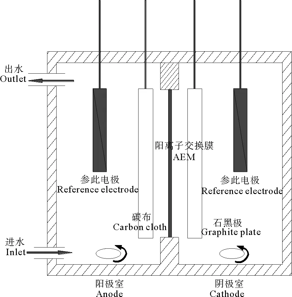
图1 双室MFC的构型
MFC阳极室使用体积比为1:1(250 mL:250 mL)的厌氧活性污泥和阳极营养液进行接种。每1 L阳极营养液中包含1.0 g葡萄糖,2.57 g NaH2PO4·2H2O,12.0 g Na2HPO4·12H2O,0.1 g KCl,0.25 g NH4Cl,5.84 g NaCl,12.5 mL的维他命溶液和12.5 mL微量金属溶液。维他命溶液和微量金属溶液的配制采用Lovley等人的配方[22]。阴极以50 mmol·L-1的磷酸盐缓冲液(PBS)作为阴极液。两极液最终用0.1 mol·L-1NaOH和0.1 mol·L-1HCl调节pH值为7.0±0.02。启动期间,每隔3d定期更换阳极液,当最少3次达到最大输出功率后改阳极为连续型,流量为0.7 mL·min-1。当输出功率达到最大并稳定后更换阴极液进行实验。
1.3 实验步骤
分别取相应体积配制好的KN-R溶液于500 mL锥形瓶中,置于恒温震荡水浴锅中预热到30 ℃,然后粗调到相应pH值后,加入一定体积的Fe2+溶液(配置好的),精调到实验要求的pH值后加入到阴极室,然后加入PDS溶液到实验所需的浓度比例并开始计时,在设定的时间点取样,并加入1 mL甲醇来淬灭氧化反应,在测量前使用0.45 μm滤膜过滤。
此外,以同样的实验步骤测定无电场条件下Fe2+/PDS体系中KN-R的脱色情况作为对比实验,同时以0.16 mmol·L-1的KN-R溶液为阴极液作为Fe2+/PDS-MFC体系的对照实验。
1.4 计算与分析
其中:DE(%)为KN-R的脱色率;A0为0时刻待测液中KN-R的吸光度值;At为t时刻待测液中KN-R的吸光度值。PDS剩余量使用碘化钾分光光度法测定[23]。pH值采用pH计测定(PHS-2F;Shanghai Precision & Scientific instrument Co., Ltd., Shanghai, China)。
2 结果与讨论
2.1 KN-R的最佳脱色条件及MFC的产电性能
在无电场条件下,Fe2+/PDS体系中KN-R的脱色情况如图3所示,当pH为3、5、7、9时体系中KN-R的脱色率分别为96.54%、85.88%、30.74%和30.82%。这与Fe2+/PDS-MFC体系有相同的趋势。这说明,外加电场条件并没有改变pH对Fe2+/PDS体系的限制作用,在相同的初始pH条件下,其对KN-R的脱色影响不大。
(4)
(5)
(6)
(7)
E0=2.01V
(8)
(9)
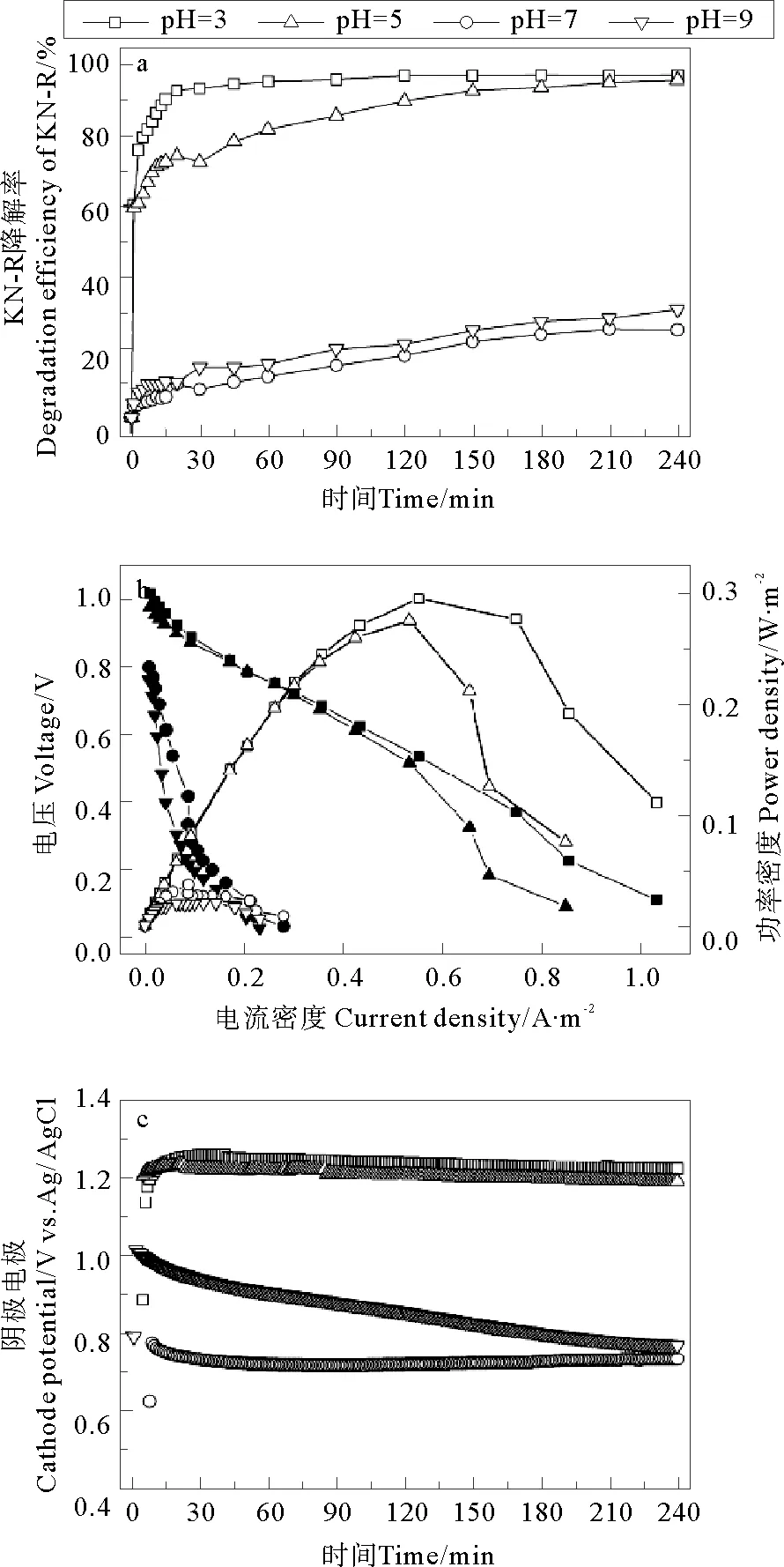
图2 初始pH对Fe2+/PDS-MFC体系中KN-R的脱色率(a),极化曲线(b)和阴极电势(c)的影响
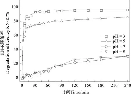
图3 初始pH对Fe2+/PDS体系中KN-R脱色率的影响

表1 不同pH值条件下MFC的阴极电势Table 1 The cathode potentials of MFC at different cathode pH conditions
注:MFC阴极液为KN-R浓度为0.16 mmol·L-1,PBS浓度50 mmol·L-1。KN-R concentration and PBS concentration are 0.16 mmol·L-1and 50 mmol·L-1respectively in cathode.

在无电场条件下,Fe2+对Fe2+/PDS体系中KN-R的脱色情况如图5所示,当Fe2+初始浓度为0、0.5、2、4、8 mmol·L-1时体系中KN-R的脱色率分别为48.68%、85.54%、97.39%、93.30%、70.27%和34.52%。与Fe2+/PDS体系相比,Fe2+/PDS-MFC体系在对应的Fe2+浓度梯度下(0 mmol·L-1除外)KN-R的脱色率略有下降。这说明,外加电场条件并没有改善Fe2+/PDS体系中Fe2+浓度的阈值问题,其优势在于体系中电能的输出。

图4 Fe2+初始浓度对Fe2+/PDS-MFC体系中KN-R脱色率(a),PDS残留量(b),极化曲线(c)和阴极电势(d)的影响
(10)
(11)
(12)
(13)
Fe2++2e-→Fe0E0=-0.44V
(14)
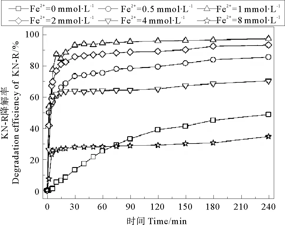
图5 Fe2+初始浓度对Fe2+/PDS体系中KN-R脱色率的影响

在无电场条件下,Fe2+/PDS体系中KN-R的脱色率与Fe2+/PDS-MFC体系有着相同的趋势。如图7所示,当PDS初始浓度在0~2 mmol·L-1之间时,KN-R的脱色率随PDS初始浓度的增加而显著提高,当PDS浓度超过2 mmol·L-1时,KN-R的脱色率也略有升高,但增加幅度不明显(PDS浓度为2 mmol·L-1时,KN-R的脱色率为97.39%,PDS浓度为8 mmol·L-1时,KN-R的脱色率为100.00%)。与Fe2+/PDS体系相比,Fe2+/PDS-MFC体系中KN-R的脱色率几乎没有改变。
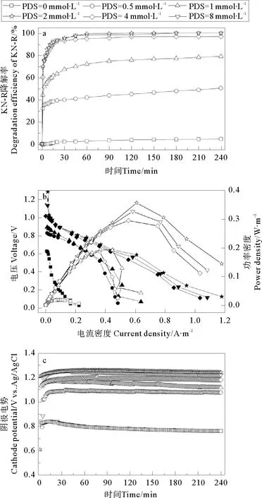
图6 PDS初始浓度对Fe2+/PDS-MFC体系中KN-R的脱色率(a),极化曲线(b)和阴极电势(c)的影响
PDS初始浓度对Fe2+/PDS-MFC体系的产电性能的影响如图6b所示,随着PDS初始浓度的增加,MFC的最大功率密度逐渐增加。当PDS初始浓度为0 mmol·L-1时,MFC的最大功率密度为18.02 mW·m-2,远低于体系中存在PDS时的最大功率密度。原因是体系中的Fe2+并不能作为电子受体(见方程14),而蒽醌结构的强稳定性也使其很难作为电子受体,MFC的阴极电势很低(见图6c)。当PDS初始浓度为0.5、1、2、4、8 mmol·L-1时,MFC的最大功率密度分别为18.02、186.35、192.91、294.07、325.91、355.71 mW·m-2。虽然体系的pH值会随着反应的进行而有所降低,但此时pH的变化对KN-R的脱色和MFC的产电性能影响不大,此时影响KN-R的脱色和MFC产电的主要因素仍然是PDS的初始浓度。随着PDS浓度的增加,体系有更多的PDS作为阴极电子受体(见方程9),进而提高了阴极电势[17]。不同PDS初始浓度下MFC阴极电势变化如图6c所示,随着PDS初始浓度的增加,阴极电势逐渐上升,MFC输出功率逐渐增大。考虑到MFC的产电性能,KN-R的脱色率和成本关系,2 mmol·L-1的PDS为体系的最佳初始浓度。

图7 PDS初始浓度对Fe2+/PDS体系中KN-R脱色率的影响
2.2 KN-R的脱色降解动力学及降解机理
2.2.1 KN-R的脱色过程的动力学分析 对不同条件下Fe2+/PDS-MFC体系中KN-R的脱色过程分别进行零级,一级和二级动力学拟合,拟合方程如下:
零级反应动力学方程:Ct=C0-k0t
一级反应动力学方程:Ct=C0ek1t
二级反应动力学方程: 1/Ct=1/C0+k2t
Ct表示t时刻KN-R的浓度;C0表示KN-R的初始浓度;k0,k1及k2分别为零级反应动力学、一级反应动力学及二级反应动力学的表观反应速率常数。
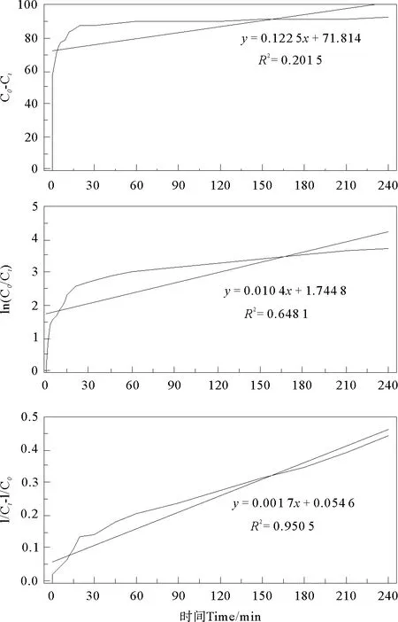
图8 KN-R脱色降解反应的零级,一级和二级动力学拟合
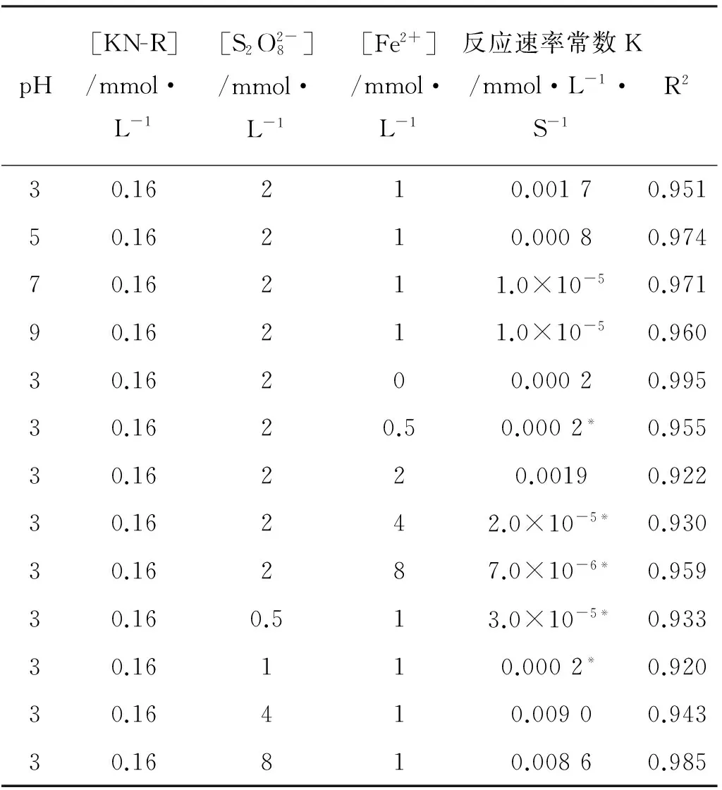
表2 不同条件下Fe2+/PDS-MFC体系中KN-R的脱色降解反应速率常数Table 2 The decoloration reaction rate constants of KN-R at different reaction conditions in Fe2+/PDS-MFC system
注:*为1~240 min内拟合结果。*Represents the fitting result in 1 to 240min.

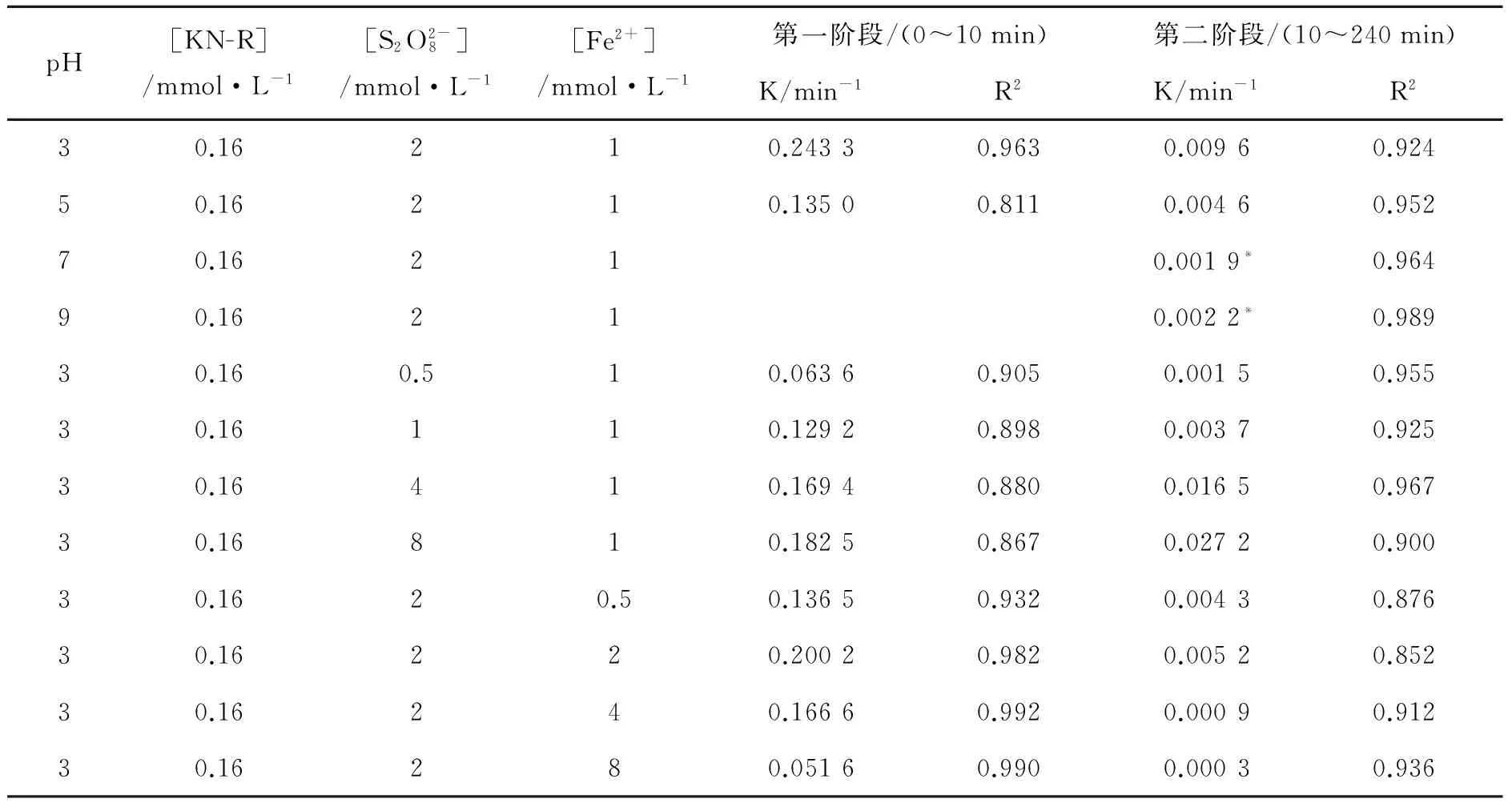
表3 不同条件下Fe2+/PDS体系中KN-R的脱色降解反应速率常数Table 3 The decoloration reaction rate constant of KN-R in the Fe2+/PDS system under different conditions
注:*表示0~20 min内的动力学拟合结果。*Represents the fitting result in 0min to 20min.
([KN-R]=0.16 mmol·L-1, [Fe2+]=1.0 mmol·L-1,[PDS]=1.0 mmol·L-1, pH=3.0,T=(30±1) ℃.[KN-R]=0.16 mmol·L-1, [Fe2+]=1.0 mmol·L-1, [PDS]=1.0 mmol·L-1, pH=3.0,T=(30±1) ℃.)
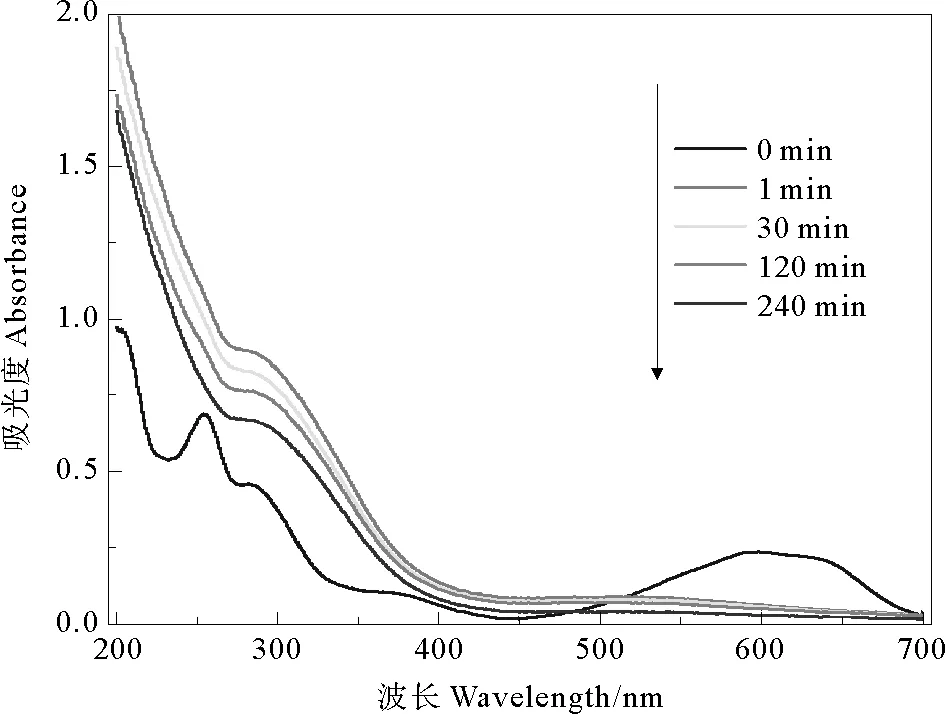
图9 KN-R脱色降解过程中紫外-可见光谱分析
Fig.9 UV-vis spectral changes of KN-R degradation
3 结语
[1] Gao J F, Zhang Q, Su K, et al. Competitive biosorption of Yellow 2G and Reactive Brilliant Red K-2G onto inactive aerobic granules: Simultaneous determination of two dyes by first-order derivative spectrophotometry and isotherm studies [J]. Bioresource Technology, 2010, 101(15): 5793-5801.
[2] Liu H N, Li G T, Qu J H, et al. Degradation of azo dye Acid Orange 7 in water by Fe0/granular activated carbon system in the presence of ultrasound [J]. Journal of Hazardous Materials, 2007, 144(1-2) : 180-186.
[3] Fan chiang J M, Tseng D H. Degradation of anthraquinone dye CI Reactive Blue 19 in aqueous solution by ozonation [J]. Chemosphere, 2009, 77(2): 214-221.
[4] 施跃锦, 马楠. 蒽醌类染料废水处理的研究进展 [J]. 化工时刊, 2009, 23(6): 49-53.
[5] Xu X R, Li X Z. Degradation of azo dye Orange G in aqueous solutions by persulfate with ferrous ion [J]. Separation and Purification Technology, 2010, 72(1): 105-111.
[6] Tan C Q, Gao N Y, Deng Y, et al. Heat-activated persulfate oxidation of diuron in water [J]. Chemical Engineering Journal, 2012, 203(1): 294-300.
[7] Neta P, Huie R E, Ross A B. Rate constants for reactions of inorganic radicals in aqueous solution [J]. Journal of Physical and Chemical Reference Data, 1988, 17(3): 1027-1284.
[8] Buxton G V, Greenstock C L, Helman W P, et al. Critical review of rate constants for reactions of hydrated electrons, hydrogen atoms and hydroxyl radicals (·OH/·O-)in aqueous solution [J]. Journal of physical and chemical reference data, 1988, 17(2): 513-886.
[9] Rastogi A, Al-Abed S R, Dionysiou D D. Effect of inorganic, synthetic and naturally occurring chelating agents on Fe (II) mediated advanced oxidation of chlorophenols [J]. Water Research, 2009, 43(3): 684-694.
[10] Tan C Q, Gao N Y, Deng Y, et al. Heat-activated persulfate oxidation of diuron in water [J]. Chemical Engineering Journal, 2012, 203(1): 294-300.
[11] Criquet J, Leitner N K V. Degradation of acetic acid with sulfate radical generated by persulfate ions photolysis [J]. Chemosphere, 2009, 77(2): 194-200.
[12] Neppolian B, Doronila A, Ashokkumar M. Sonochemical oxidation of arsenic (III) to arsenic (V) using potassium peroxydisulfate as an oxidizing agent [J]. Water research, 2010, 44(12): 3687-3695.
[13] Tan C Q, Gao N Y, Deng Y, et al. Heat-activated persulfate oxidation of diuron in water [J]. Chemical Engineering Journal, 2012, 203(1): 294-300.
[14] Banerjee M, Konar R S. Comment on the paper “polymerization of acrylonitrile initiated by K2S2O8Fe (II) redox system” [J]. Journal of Polymer Science: Polymer Chemistry Edition, 1984, 22(5): 1193-1195.
[15] Mcelroy W J, Waygood S J. Kinetics of the reactions of theradical with,H2O and Fe2+[J]. Journal of the Chemical Society, Faraday Transactions, 1990,86(14): 2557-2564.
[16] Cusick R D, Kiely P D, Logan B E. A monetary comparison of energy recovered from microbial fuel cells and microbial electrolysis cells fed winery or domestic wastewaters [J]. International Journal of Hydrogen Energy, 2010, 35(17): 8855-8861.
[17] Wang Y, Niu C G, Zeng G M, et al. Microbial fuel cell using ferrous ion activated persulfate as a cathodic reactant [J]. International Journal of Hydrogen Energy, 2011, 36(23): 15344-15351.
[18] Choi C, Cui Y. Recovery of silver from wastewater coupled with power generation using a microbial fuel cell [J]. Bioresource Technology, 2012, 107: 522-525.
[19] 张金娜. 三种不同阴极类型微生物燃料电池产电性能研究 [D]. 哈尔滨: 哈尔滨工业大学,2009.
[20] Liu L, Li F, Feng C, et al. Microbial fuel cell with an azo-dye-feeding cathode [J]. Applied Microbiology and Biotechnology, 2009, 85(1): 175-183.
[21] Wang Z, Lim B, Choi C. Removal of Hg2+as an electron acceptor coupled with power generation using a microbial fuel cell [J]. Bioresource Technology, 2011, 102(10): 6304-6307.
[22] Lovely D R, Phillips E J P. Novel mode of microbial energy metabolism: organism carbon oxidation coupled to dissimilatory reduction of iron and manganese [J]. Appl Environ Microbiol 1988, 54: 1472-1480.
[23] Liang C, Huang C F, Mohanty N, et al. A rapid spectrophotometric determination of persulfate anion in ISCO [J]. Chemosphere, 2008, 73(9): 1540-1543.
[24] Zhuang L, Zhou S, Li Y, et al. Enhanced performance of air-cathode two-chamber microbial fuel cells with high-pH anode and low-pH cathode [J]. Bioresource Technology, 2010, 101(10): 3514-3519.
[25] Liang C, Bruell C J, Marley M C, et al. Persulfate oxidation for in situ remediation of TCE. I. Activated by ferrous ion with and without a persulfate-thiosulfate redox couple [J]. Chemosphere, 2004, 55(9): 1213-1223.
[26] Liang C, Bruell C J, Marley M C, et al. Persulfate oxidation for in situ remediation of TCE. II. Activated by chelated ferrous ion [J]. Chemosphere, 2004, 55(9): 1225-1233.
[27] Li J, Fu Q, Liao Q, et al. Persulfate: A self-activated cathodic electron acceptor for microbial fuel cells [J]. Journal of Power Sources, 2009, 194(1): 269-274.
[28] Mcelroy W J, Waygood S J. Kinetics of the reactions of theradical with,H2O and Fe2+[J].Journal of the Chemical Society, Faraday Transactions, 1990,86(14): 2557-2564.
[29] Niu C G, Wang Y, Zhang X G, et al. Decolorization of an azo dye Orange G in microbial fuel cells using Fe (II)-EDTA catalyzed persulfate [J]. Bioresource Technology, 2012, 126: 101-106.
[30] W Kamp. Organic Spectroscopy [M]. [s.l.]:The MacMillian Press Ltd, 1975.
[31] R.M. Christie, Colour chemistry, Royal Society of Chemistry, 2001.Christie R M.Colour Chemistry[M].[s.l.]: Royal Society of Chemistry,2001.
[32] 陈国珍,黄贤智,刘文远,等. 紫外-可见分光光度法上册 [M]. 北京: 原子能出版社,1986: 10.
[33] Tsitonaki A, Petri B, Crimi M, et al. In situ chemical oxidation of contaminated soil and groundwater using persulfate: a review [J]. Critical Reviews in Environmental Science and Technology, 2010, 40(1): 55-91.
责任编辑 徐 环
Decolorization of an Anthraquinone Dye Reactive Brilliant Blue KN-R in Microbial Fuel Cells Using Ferrous Catalyzed Persulfate
JIN Chun-Ji1,2,YU Hui1,LIU Ming1,SUN Ruo-Chen1,YANG Yuan-Le1
(1. College of Environmental Science and Engineering, Ocean University of China, Qingdao 266100, China; 2. The Key Laboratory of Marine Environment and Ecology, Ministry of Education, Ocean University of China, Qingdao 266100, China)
This study constructed a double chamber microbial fuel cell (MFC), with ferrous iron/persulfate system (Fe2+/ PDS) as the cathode liquid and the anthraquinone dye Reactive Brilliant Blue KN-R as the goal pollutants. It investigated initial Fe2+dosage, PDS concentration, pH on the KN-R decoloration rate and the electrogenesis capacity of MFC. The results showed that the KN-R had the largest degradation rate at the condition of initial pH, Fe2+and PDS concentration was 3, 1 mmol·L-1, 2 mmol·L-1, respectively. The maximum degradation rate was 96.90% and the maximum power density of the MFC was 294.07 mW·m-2. Dynamics analysis showed that the decoloration process followed the second-order kinetic model and the reaction rate constant was 0.001 7 mmol·L-1· min-1under optimum condition. Uv-vis spectrum analysis showed that the Fe2+/ PDS-MFC system can degrade KN-R and its intermediate products effectively.
microbial fuel cell; ferrous; persulfate; KN-R degradation; maximum power density
山东省自然科学基金项目(ZR2011BM014)资助
2014-03-13;
2014-04-23
金春姬(1968-), 女, 博士,副教授。 E-mail:jinhou@ouc.edu.cn
O646.21
A
1672-5174(2015)04-085-10
10.16441/j.cnki.hdxb.20140088