Ski jump trajectory with consideration of air resistance*
2015-02-16WUJianhua吴建华ZHANGXiaoyan张晓艳MAFei马飞WUWeiwei吴伟伟
WU Jian-hua (吴建华), ZHANG Xiao-yan (张晓艳), MA Fei (马飞), WU Wei-wei (吴伟伟)
1. College of Water Conservancy and Hydropower Engineering, Hohai University, Nanjing 210098, China, E-mail:jhwu@hhu.edu.cn
2. Hydraulic Structure Design Division, Hydrochina Huadong Engineering Corporation, Hangzhou 310014, China
Ski jump trajectory with consideration of air resistance*
WU Jian-hua (吴建华)1, ZHANG Xiao-yan (张晓艳)1, MA Fei (马飞)1, WU Wei-wei (吴伟伟)2
1. College of Water Conservancy and Hydropower Engineering, Hohai University, Nanjing 210098, China, E-mail:jhwu@hhu.edu.cn
2. Hydraulic Structure Design Division, Hydrochina Huadong Engineering Corporation, Hangzhou 310014, China
(Received February 15, 2015, Revised May 25, 2015)
In the case of the ski-jump type energy dissipation, the jet trajectory will be greatly affected by the air entrainment and the air resistance. It is necessary to consider those factors when estimating the trajectory of the jet flow. In this work, the effect of the air resistance on the jet trajectory is theoretically and experimentally investigated. A comprehensive resistance coefficient is proposed. To determine this coefficient, experiments of five models are conducted with the circular-shaped flip bucket placed at the point of the takeoff of ski jumps. It is shown that, this coefficient of the lower jet trajectory is only related to the approach flow Froude number, while that of the upper jet trajectory is dominated by both this Froude number and the deflection angle. Furthermore, the present methodology is validated by experimental data in this work and the maximum errors are not larger than 3.2% and 8.6% for the lower and upper jet trajectories, respectively.
trajectory, jet flow, comprehensive resistance coefficient, hydropower project
The jet flow trajectory through a ski-jump is an important issue in the designs with respect to the skijump type energy dissipation. In practical projects, the jet flow will split and the air will be entrained into the flow when it leaves from the flip bucket, and the trajectory will be greatly affected by the air entrainment and the air resistance. It is necessary to consider those factors when estimating the trajectory of the jet flow.
Figure 1 shows a plane ski-jump flow with related notation definitions. The origin of the coordinate system (x, y)is at the edge of the flip bucket. In this figure,Voand hoare the approach flow velocity and depth, respectively, at the acting water head Ho,Roandβare the radius and the deflection angle of the circular-shaped flip bucket, respectively,αLand αUare the virtual take-off angles of both the lower (subscriptL ) and upper (subscriptU ) jet trajectories,xLand xUare the impact points of the jet onto the tailwater channel, determined visually from the channel side, by extending the jet trajectories, andsis the height from the edge of the flip bucket to the tailwater channel bottom. The objectives of this paper are to theoretically and experimentally investigate the effects of the air resistance on the jet trajectory, and to determine these influencing factors.
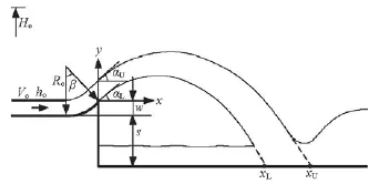
Fig.1 A plane ski-jump flow with related notation definitions
On the basis of the theory of the projectile for a rigid body[1], the trajectory of a mass point withoutconsideration of the air resistance FAcan be expressed as
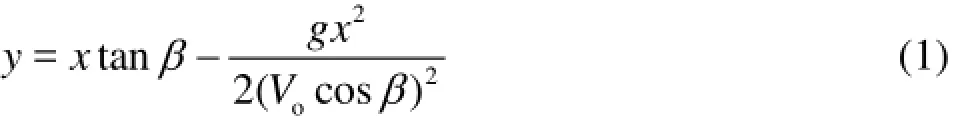
where g=9.81m2/s, is the acceleration of the gravity.
For the jet flow from the flip bucket (Fig.1), the trajectory under the action of the air resistance is
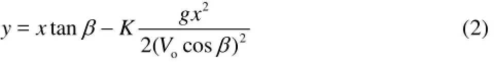
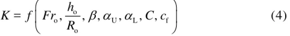
whereK is called the comprehensive resistance coefficient. Liu and Zhang theoretically presented an expression ofK , but there are some variables in the expression that cannot be obtained, including the density ratio of air (ρa)and jet flow (ρw), and the resistance coefficient (cf). Using the field data of eight projects about the location of the deepest scour, they decided thatKis only a function of the approach flow Froude number (Fro)[2]. In fact,Kmight be related to the geometric parameters of the flip bucket, and the hydraulic parameters of the approach flow and the jet flow. For a circular-shaped flip bucket,Kcould be constructed as (Fig.1)

whereC is the average air concentration of the flow section,, the resistance coefficient of the air towards the flow, andAis the section area of the flow. Equation (3) could be rewritten in view of dimensional analysis as
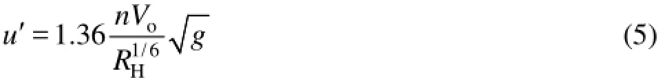
wheren is the Manning roughness coefficient, and RHis the hydraulic radius. Then we have

While RHis equal approximately to hodue to the small flow depth relative to the width of the flip bucket, then Eq.(6) becomes
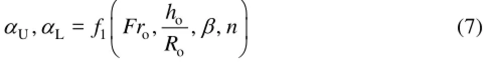
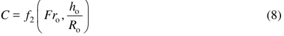
Secondly, the air concentration(C)of the flow is dominated by the relative depth of the flow(ho/ Ro)and the approach flow Froude number (Fro)if the air density (ρa)is considered as a constant[5], thus,
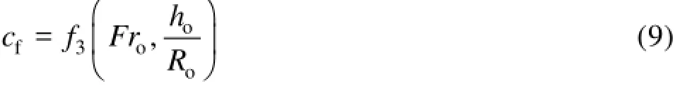
At the same time, the resistance coefficient (cf)is related with the section form of the flow, and depends onho/Roand Fro. Therefore,cfcould be written as
On the basis of Eqs.(7)-(9), Eq.(4) could be simplified as
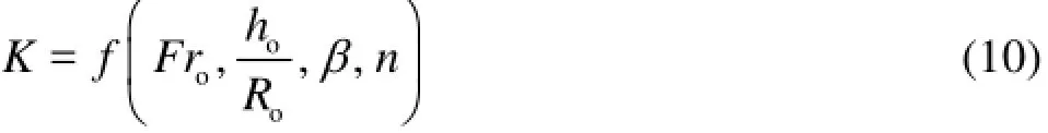
For the flip bucket of the same material, the Manning roughness coefficient(n)is equal to a constant. Neglectingn , Eq.(10) could finally be rewritten as
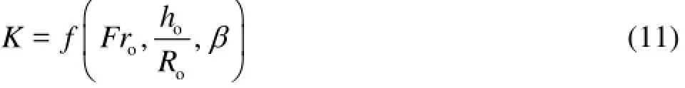
This implies that the comprehensive resistance coefficient(K)is a function of Fro,ho/Roandβ. With an appropriate experimental procedure, the variations of the variable parameters in the comprehensive resistance coefficient in Eq.(11) can be determined to find the effect of each parameter separately on K.
The experiments are conducted in the High-speedFlow Laboratory of Hohai University. The circularshaped flip bucket is placed at the outlet of a discharge tunnel. It is horizontally 21.70 m in length and 0.15 m in width. The jet flow from the model flip bucket is shown in Fig.2. There are two sets of test models, named by Mij, where i=1, 2 and 3, stands for deflection angleβ=15o,25oand 35o, respectively, withRo=1.00 m,j =1, 2 and 3, stands for R=0.40 m, 1.00 m and 1.50 m with β=25o, and
os =0.65 mand w=Ro(1-cosβ)(Fig.1). For each model, the relationships of Eq.(11) are experimentally investigated at five acting heads.
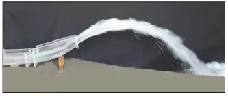
Fig.2 Experimental setup and outlet flow
On the basis of Eq.(11),K may be expressed in independent functions F1to F3accounting for the main parameters of the present research as
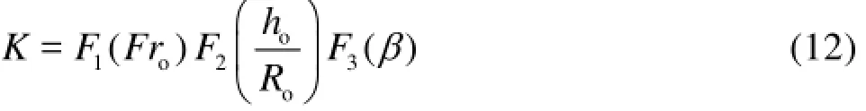
For the lower and upper jet trajectories,K is replaced by KLand KU.

Fig.3 Variations of K/Frwith h/Rat β=25oLooo
Equation (12) for KLcan be rewritten as
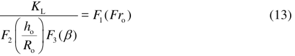
Figure 3 demonstrates that the relationship between KLand Frotakes the form KL/Fro≈0.252 (R2=0.008). It means that h/Rhas little effect on
ooKL/Froin the range 0.02≤ho/Ro≤0.15. Thus, Eq.(13) could be simplified as
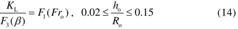
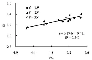
Fig.4 Variations of KLwith Froat Ro=1.0 m
Figure 4 shows the relationship KL=0.174Fro+ 0.411(R2=0.084)for β=15o,25oand 35o, and it can be seen that the effect of the deflection angleβ could be neglected in the range 15o≤β≤35o15. We have
KL=F1( Fro),15o≤β≤35oand
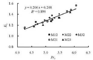
Fig.5 Relationship between KLand Fro
Furthermore, from Fig.5, the best fit of Eq.(15) is (R2=0.890)

Equation (16) shows that KLis a linear function of Fro.
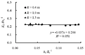
Fig.6 Variations of K/Frwith h/Rat β=25oUooo
Similar to Eq.(14),KUcould be obtained on the basis of Fig.6(R2=0.051)as
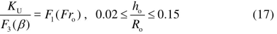
It implies that KU/Frois not influenced by ho/Roin the range 0.02≤ho/Ro≤0.15. According to Fig.7, KU(Fro)has different characteristics for differentβ. The slope ofKU(Fro)increases with the increase of the deflection angleβ.
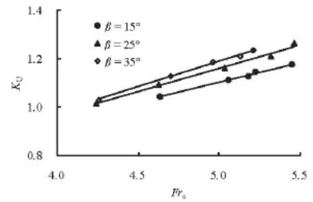
Fig.7 Variations of KUwith Froat Ro=1.0 m
In order to obtain the relationship given by Eq.(17), a function reflecting the effects of F3(β)on KUis constructed as follows
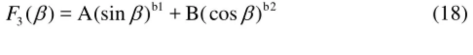
whereAandB are constants, and b1andb2are exponents of the functionssinβandcosβ, respectively. By means of the regression analysis, we have

Finally, from Fig.8(R2=0.899), we have
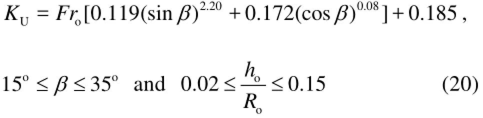
This equation demonstrates that KUis dominated by both Froandβunder the conditions of the present research.
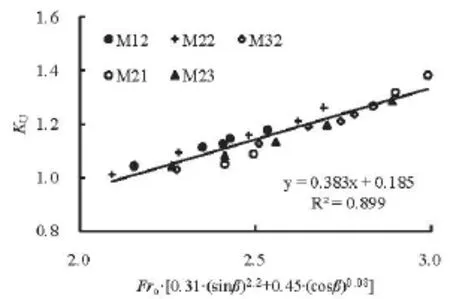
Fig.8 Relationship between Kand Fr[0.31(sinβ)2.2+Uo0.45(cosβ)0.08]
Comparing with the experimental data, the relative errors of Eq.(20) are not larger than 3.2 and 8.6%, respectively, when estimating both KLand KUusing the methodology in this paper.
[1] PLUMPTON C., TOMKYS W. A. Theoretical mechanics for sixth form[M]. Hongkong, China: Book Marketing Ltd., 1989.
[2] LIU Xuan-lie, ZHANG Wen-zhou. Effect of air resistance on jet trajectory[J]. Journal of Tianjin University, 1982, 28(2): 67-78(in Chinese).
[3] HELLER V., HAGER W. H. Ski jump hydraulics[J]. Journal of Hydraulic Engineering, ASCE, 2005, 131(5): 347-355.
[4] WU Jian-hua, RUAN Shi-ping. Cavity length below chute aerators[J]. Science China, Series E: Technology Sciences 2008, 51(2): 170-178.
[5] SCHMOCKER L., PFISTER M. and HAGER W. H. et al. Aeration characteristics of ski jump jets[J]. Journal of Hydraulic Engineering, ASCE, 2008, 134(1): 90-97.
* Project supported by the National Natural Science Foundation of China (Grant No. 51179056).
Biography: WU Jian-hua (1958-), Male, Ph. D., Professor
猜你喜欢
杂志排行

水动力学研究与进展 B辑的其它文章
- Multi-scale Runge-Kutta_Galerkin method for solving one-dimensional KdV and Burgers equations*
- Effect of channel shape on selection of time marching scheme in the discontinuous Galerkin method for 1-D open channel flow*
- The impact of macroalgae on mean and turbulent flow fields*
- Numerical study of the performance of multistage Scaba 6SRGT impellers for the agitation of yield stress fluids in cylindrical tanks*
- Selection of organic Rankine cycle working fluids in the low-temperature waste heat utilization*
- United friction resistance in open channel flows*