Caustics study of the effect of glass fibres on dynamic fracture of hardened cement paste
2014-09-06YangLiyunYangRenshuZhaoXuenanFangShizheng
Yang Liyun Yang Renshu Zhao Xuenan Fang Shizheng
(School of Mechanics and Civil Engineering, China University of Mining & Technology, Beijing 100083, China)
Caustics study of the effect of glass fibres on dynamic fracture of hardened cement paste
Yang Liyun Yang Renshu Zhao Xuenan Fang Shizheng
(School of Mechanics and Civil Engineering, China University of Mining & Technology, Beijing 100083, China)
The reflected optical caustics method is applied to study dynamic fracture problems in hardened cement paste. First, both the unreinforced cement paste and the glass fibres reinforced cement paste specimens were fabricated and the reflective coating on the surface of the specimen was prepared. Secondly, the crack path and the shadow spot patterns during the crack propagation process for the two specimens were recorded by using a multi-spark high speed camera. Thirdly, some dynamic parameters of two cement paste specimens, including crack onset time, the dynamic stress intensity factor and crack growth velocity were determined and analyzed comparatively. This indicates that the glass fibres can improve the fracture resistance and delay fracture time. These results will play an important role in evaluating the dynamic fracture properties of cement paste.
reflected optical caustics; cement paste; glass fibre; dynamic fracture; dynamic stress intensity factor
As a construction material, hardened cement paste is commonly used in civil/mining engineering. Usually unreinforced cement paste materials are characterized with low tensile strength, low fracture toughness and low tensile strain capacities. The inclusion of short discrete fibres in cement paste, however, can largely enhance its engineering properties, such as fracture toughness, tensile strength, flexural strength, resistance to fatigue, impact and thermal shock[1]. So there has been a steady increase in the use of short and randomly distributed fibres to reinforce cement[2-5]. Many researchers have been carrying out multiple theoretical and experimental research about the dynamic fracture mechanics of reinforced and unreinforced cement paste, which indicates that the inclusion of fibres improves the fracture toughness and impact resistance of cementitious materials[6-10]. Among many experimental techniques, the optical method of caustics has been proved to be very effective for fracture study. The advantage of this experimental method lies in its simple optical patterns, which can establish the relationship between the stress field parameters and the characteristic size of the caustics curve[11-14]. Today the caustics method has been widely used in fracture problems of various advanced materials, such as birefrigent materials[15], anisotropic materials[16-17], rock-like materials[18], composite and nano-composite materials[19-20]. Yao et al.[17, 20]studied the dynamic evolutions of stress singularities at mode Ⅰ crack tip in laminated composites by combining caustics with high-speed photography. Yao et al.[21]also studied the local stress singularities of the laminate composite materials under dynamic concentrated loads by caustics. Li et al.[22]investigated the dynamic fracture toughness and the crack growth velocity of polypropylene/nylon6 (PP/PA6) blends with different weight fractions and different compatibilizers by means of the reflected caustics. Gong et al.[23-25]studied dynamic mode Ⅰ and mixed-mode fracture problems of typical glass fibre-reinforced composites using the caustics, which indicates that the arrangement of fibres has a larger influence on the fracture process than the volume ratio of fibres.
In this paper, the reflected caustic is applied to investigate dynamic fracture problems in hardened cement paste. Some important fracture parameters, including crack onset time, dynamic fracture toughness and crack growth velocity, are determined and compared with each other for both unreinforced cement paste and glass fibres reinforced cement paste.
1 The Reflected Caustics Method
The caustics method discovered by Manogg was popular in early dynamic fracture investigations due to its simplicity, which provided a direct determination of the stress intensity factor by means of measuring the caustics size at the crack tip. The optical principles of light beam deflections for the reflected caustics are shown in Fig.1. When a parallel light beam impinges on the lateral face of the crack tip subjected to in-plane loading, it is reflected from the face of the specimen. Also, a virtual image can be obtained in the reference plane located behind the specimen at a distanceZ0. The reflected caustics with a dark spot surrounded by a bright curve are obtained on this reference plane. The dark spot and bright curve are recorded by a camera focused on the reference plane. In the presence of a crack, the caustics pattern is an approximately circular dark region on the crack tip as shown in Fig.2. The size of the caustics curve can be related to the stress intensity factor by introducing an analysis based on geometrical optics and fracture mechanics. For mode Ⅰ loading, the transverse diameter is related to the stress intensity factor through the following relationship[11]:
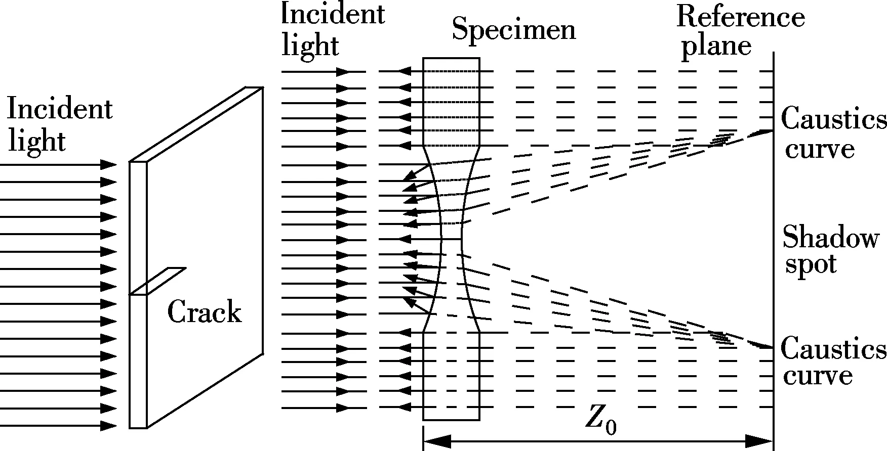
Fig.1 Principle of virtual caustics near crack tip
(1)
wherehis the plate thickness;Z0is the distance between the specimen plane and the reference plane; andF(v) is a correction factor for a crack propagating dynamically at a speedv;cis the optical constants for opaque specimens. Thus, from measurements of the transverse diameterDof the caustics curve, the dynamic stress intensity factor can be determined.
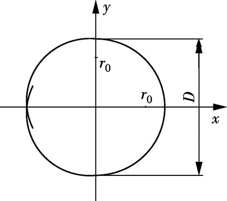
Fig.2 Schematic illustration of virtual caustics spot of a tension specimen
2 Experimental Details
2.1 Hardened cement paste
In this study, the hardened cement paste consists of Portland cement, potable water, water reducer and latex powder. Two types of specimens are prepared. One is the unreinforced cement paste, named specimen A; the other is glass fibres reinforced cement paste, named specimen B. Specimen A consists of Portland cement, potable water, water reducer and latex powder in the ratio of 2000∶9000∶18.04∶900 (see Fig.3). Specimen B consists of potable water, Portland cement, water reducer, latex powder and glass fibres in the ratio of 2000∶9000∶18.04∶900∶18.04. So the weight content of glass fibres in the reinforced cement paste specimens is 1.5‰. After some special technologies such as mixing, stirring, curing and demoulding, a plate specimen with a dimension of 300 mm×300 mm×10 mm is manufactured.
To characterize the dynamic elastic properties of the cement paste, the ultrasonic wave method is used. The density and wave speed of the unreinforced cement paste and glass fibres reinforced cement paste specimen are approximately equal to the additional low content glass fibres. The related physical and mechanical properties of the cement paste plates are shown in Tab.1, whereρis the density of material;Cpis the longitudinal wave speed;Csis the shear wave speed;Eis Young’s modulus;υis Poisson’s ratio;Gis the shear modulus.
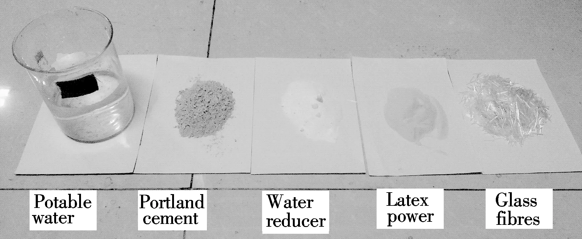
Fig.3 Materials used
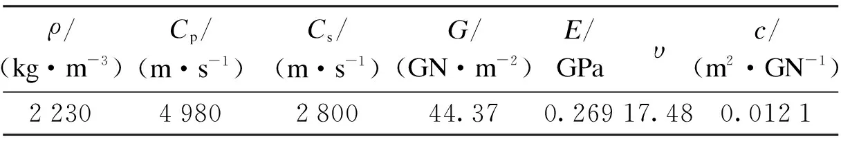
Tab.1 Dynamic properties of unreinforced cement paste and glass fibres reinforced cement paste
Finally, the rectangular coupons with a dimension of 220 mm×50 mm×8 mm are machined. An edge notch of 10 mm in length and 0.5 mm in width is cut using a circular saw of the thickness 300 μm.
Due to the non-transparency of the cement paste, the surface of the specimen should be prepared by the following procedure[17, 20]: an optically flat glass plate is coated with thin aluminum of 50 nm in thicknesses. The coated glass is then affixed to the sample using an epoxy adhesive, which glues the coated surface of the optically flat glass to the sample. The epoxy adhesive is a mixture of epoxy resin and hardener. After the epoxy is cured, the glass was peeled off, and then a thin reflective coating was transferred to its surface with epoxy resin for reflection. The total thickness of the epoxy layer and the coating is merely a couple of microns. Compared to the sample thickness, this layer is very thin and will not affect the deformation state inside the specimen. Fig.4 shows a specimen image with a reflective coating before testing.

Fig.4 The specimen before test
2.2 Experimental setup
The specimen was mounted in a drop weigh tower with a 1.5 kg free-falling weight at 0.5 m height, which is able to achieve impacts at low loading rates. The experimental optical equipment of a multi-spark high speed camera is shown in Fig.5, which consists of a 4×4 array point light source, field lens and half-reflective lens and a 4×4 array camera. For this equipment, the output aperture of the spark gap should be as small as possible to produce a point light source for obtaining the caustics spot. The light from each spark is first reflected by the mirror surface of the specimen, and then enters the camera where the specimen off-focused images are obtained. Synchronizations of the impact load with the sparks are achieved by means of a time sequence controlled circuit. In this test, the distance between the reference plane and the specimen plan is 0.65 m.
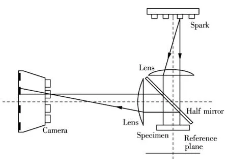
Fig.5 Optical arrangement for the caustics with multi-spark high speed camera
3 Results and Discussion
3.1 Dynamic caustic patterns
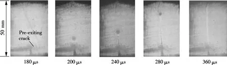
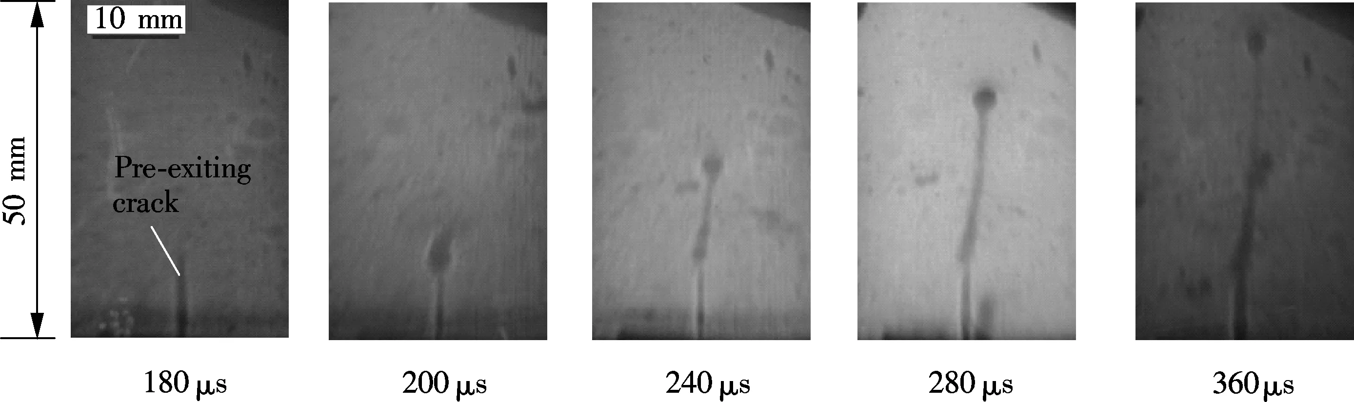
The typical dynamic caustics image patterns surrounding the running crack tip for two types of cement pastes are shown in Fig.6. Their time interval frame is 20 μs. According to the method of caustics, the light rays impinge normally at the specimen and the reflected rays from the front face of the specimen are deviated becauseof the important constraint of the specimen at the vicinity of the crack tip. The deviated light rays, when projectedonto a reference screen, are concentrated along a singular curve, which is strongly illuminated and develops the caustics. Their geometrical shapes have a similar appearance to two materials, but their caustics sizes and locations under the same loading level are different from each other, which strongly depend on the elastic properties at the crack tip. Since the crack is under the mode Ⅰ loading, the caustics is basically a symmetrical circular curve about the crack plane. Meanwhile, the crack is slightly curved, as shown in Fig.7, which means that the caustic spot maybe Ⅰ+Ⅱ pattern. However, it can be seen that the crack has a very slight curve and the caustics pattern approaches mode Ⅰ pattern, so the mode Ⅱ effects are ignored in the following descriptions.
The variations of the diameter of the caustics for the propagating crack tip along with the time are shown in Fig.7. According to the optical patterns of the crack propagation, some important dynamic fracture parameters such as the crack length, the crack velocity and the dynamic fracture intensity factors can be obtained.
(a)
(b)
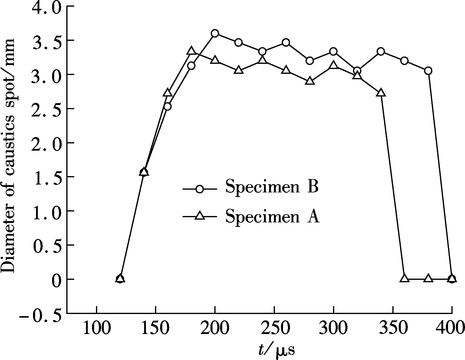
Fig.7 The variation of the caustics spot diameter
3.2 Crack length and velocity
The crack tip location during the crack propagation that follows the initial crack line exactly can be precisely determined by the caustics images. Thus, the crack growth length at each time instant is measured. The crack length histories for specimens A and B are plotted in Fig.8. The crack-tip velocity is then computed based on the crack length data against time. Before calculating the crack velocity, the data sets were smoothed using cubic Bezier curves and the crack velocity was evaluated at the mid-point of each interval. The smoothed values were used to extract the crack velocity using the central difference method. The related experimental results are shown in Fig.8.
(a)
(b)
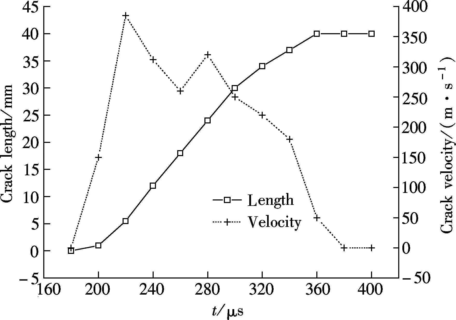
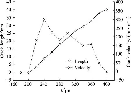
Fig.8 shows the dynamic propagation history of mode Ⅰ crack for specimen A (unreinforced cement paste) and specimen B (glass fibres reinforced cement paste), including the crack length and crack velocity. It can be seen that the crack initiation time is different for the two types of specimens under the same loading conditions. The crack in specimen A initiates at 200 μs first, while the crack in specimen B initiates at 220 μs. It can be concluded that the glass fibres delay the crack initiation. Also, it can be seen that the whole fracture process of specimens A and B last for 160 and 180 μs, respectively. Clearly, the glass fibres delay the fracture time.
From Fig.8, it is observed that the crack velocityvoscillated with the increase in the crack length. There exist several stages of recognizablevincreasing, decreasing, re-increasing and re-decreasing regions during the whole fracture process. Both the wavy and the fluctuation variations of the crack velocityvindicate that there is a strong influence of the stress wave created at each time instant from the crack tip and reflected from the boundary. Moreover, the interactions between the boundary and the crack becomes more and more significant as the crack approaches the boundary.
During the whole fracture process of the specimens, the maximum velocities of specimens A and B are about 385 and 300 m/s, respectively, which corresponds to about 220 and 240 μs of the fracture time. Clearly, the glass fibres can not only reduce the crack velocity to a certain extent, but also delay the fracture time slightly.
3.3 Evolution of stress intensity factors
According to the caustics fracture experiment of two types of cement paste specimens and the above-stated data processing procedure, the evolution of the stress intensity factorKⅠat the crack tip for specimen A and specimen B under different impact times are shown in Fig.9.
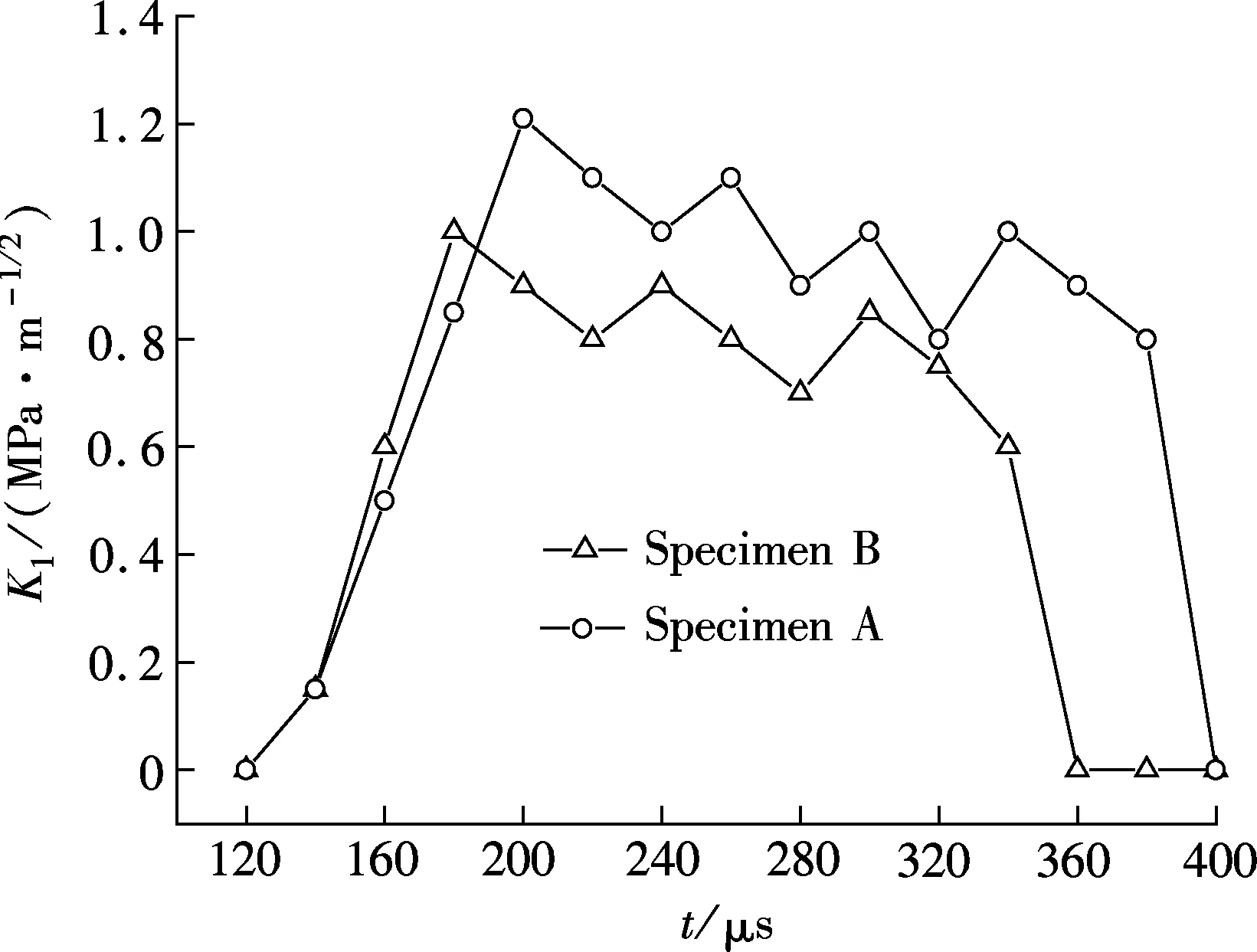
Fig.9 Evolution of dynamic stress intensity factors
From Fig.9, it can be seen that the caustics spot appeared at about 140 μs and the stress intensity factor increased sharply before crack initiation. It is found that the crack starts propagation when the stress intensity factor reaches its highest value. Also, the stress intensity factor value begins to drop slowly and shows oscillation for the interactions among the stress wave, the reflective stress wave and the crack.
In Fig.9, it can be seen that the stress intensity factor of specimen A reaches the maximum value of 1.013 MPa·m1/2at 180 μs, which is the crack initiation time, while the maximum value of the stress intensity factor of specimen B is about 1.215 MPa·m1/2at 200 μs. Thus, it can be concluded that the glass fibres improve the fracture toughness by 20%.
4 Conclusions
1) Dynamic reflected caustics are performed successfully using a multi-spark high-speed camera, which shows that the reflected caustics is an efficient experimental method to investigate the dynamic fracture process and the dynamic fracture mechanism of cement paste.
2) Crack onset time, dynamic fracture toughness and crack growth velocity of two types of hardened cement paste are obtained from the experiments.
3) The glass fibres improve the fracture toughness by 20%, delay the crack initiation time by 20 μs, and decrease the crack propagation velocity by 85 m/s. These results play an important role in evaluating the dynamic fracture properties of cement paste.
[1]Holister G S, Thomas C.Fibrereinforcedmaterials[M]. Amsterdam:Elsevier Pub. Co., 1966.
[2]Aziz M A, Paramasivam P, Lee S L. Prospects for natural fibre reinforced concretes in construction[J].InternationalJournalofCementCompositesandLightweightConcrete, 1981, 3(2):123-132.
[3]Brandt A M. Fibre reinforced cement-based (FRC) composites after over 40 years of development in building and civil engineering[J].CompositeStructures, 2008, 86(1/2/3):3-9.
[4]Potrzebowski J. Investigation of steel-fibres debonding processes in cement paste[C]//ProceedingofInternationalConferenceinBondinConcrete. Paisley, 1986.
[5]Zheng Z, Feldman D. Synthetic fibre-reinforced concrete[J].ProgressinPolymerScience, 1995, 20(2):185-210.
[6]Mindess S, Banthia N P, Ritter A, et al. Crack development in cementitious materials under impact loading[C]//MRSProceedings, 1985, 64:217.
[7]Ramakrishna G, Sundararajan T. Impact strength of a few natural fibre reinforced cement mortar slabs: a comparative study[J].CementandConcreteComposites, 2005, 27(5):547-553.
[8]Savastano Jr H, Santos S F, Radonjic M, et al. Fracture and fatigue of natural fiber-reinforced cementitious composites[J].CementandConcreteComposites, 2009, 31(4):232-243.
[9]Zhang J, Li V C. Simulation of crack propagation in fiber-reinforced concrete by fracture mechanics[J].CementandConcreteResearch, 2004, 34(2):333-339.
[10]Zhou X, Ghaffar S H, Dong W, et al. Fracture and impact properties of short discrete jute fibre-reinforced cementitious composites[J].Materials&Design, 2013, 49:35-47.
[11]Kalthoff J F. The shadow optical method of caustics[M]//Kobayashi A S. Handbook on Experimental Mechanics. Wiley, 1993.
[12]Papadopoulos G A.Fracturemechanics:theexperimentalmethodofcausticsandthedet.-criterionoffracture[M]. Springer-Verlag, 1993.
[13]Papadopoulos G A. Crack-tip caustics at a bi-material interface[J].InternationalJournalofFracture, 1999, 98(3/4):329-342.
[14]Rosakis A J. Analysis of the optical method of caustics for dynamic crack propagation[J].EngineeringFractureMechanics, 1980, 13(2):331-347.
[15]Papadopoulos G A, Pazis D. The non-linear solution of the mixed-mode caustics in birefringent materials[J].InternationalJournalofFracture, 2003, 119(2):35-40.
[16]Yao X F, Meng L B, Yeh H Y. Influence of material orientation on crack tip stress singularity in orthotropic composites[J].ModellingandSimulationinMaterialsScienceandEngineering, 2005, 13(7):1047.
[17]Yao X F, Xu W, Jin G C, et al. Low velocity impact study of laminate composites with mode I crack using dynamic optical caustics[J].JournalofReinforcedPlasticsandComposites, 2004, 23(17):1833-1844.
[18]Yang R, Yue Z, Sun Z, et al. Dynamic fracture behavior of rock under impact load using the caustics method[J].MiningScienceandTechnology(China), 2009, 19(1):79-83.(in Chinese)
[19]Yao X F, Yeh H, Zhao H P. Dynamic response and fracture characterization of polymer-clay nanocomposites with mode-I crack[J].JournalofCompositeMaterials, 2005, 39(16):1487-1496.
[20]Yao X, Chen J, Jin G, et al. Caustic analysis of stress singularities in orthotropic composite materials with mode-I crack[J].CompositesScienceandTechnology, 2004, 64(7):917-924.
[21]Yao X F, Xu W, Xu M Q, et al. Caustic study on stress singularities in laminated composites under concentrated loads[J].InternationalJournalofSolidsandStructures, 2004, 41(13):3383-3393.
[22]Li Z, Wang J, Qin W Z. Dynamic fracture behaviors of polypropylene/polyamide-6 blends[J].KeyEngineeringMaterials, 2006, 324:887-890.
[23]Gong K Z, Li Z. Caustics method in dynamic fracture problem of orthotropic materials[J].OpticsandLasersinEngineering, 2008, 46(8):614-619.
[24]Gong K, Li Z, Qin W Z. Influence of loading rate on dynamic fracture behavior of fiber-reinforced composites[J].ActaMechanicaSolidaSinica, 2008, 21(5):457-460.
[25]Gong K Z, Qin W Z, Li Z, et al. Dynamic fracture of mode I crack in orthotropic composites studied by caustics method[J].KeyEngineeringMaterials, 2006, 326-328:1003-1006.
玻璃纤维对水泥石强化效应的焦散线实验研究
杨立云 杨仁树 赵雪楠 方士正
(中国矿业大学(北京)力学与建筑工程学院, 北京 100083)
采用反射式焦散线方法对水泥石中添加玻璃纤维后的强度变化问题进行了实验研究.首先,制作了不添加与添加玻璃纤维的2种水泥石试件,并采用镜面移植方法在试件的表面进行反射镜面的制作与加工.然后,采用多火花式高速摄影系统对试件在冲击断裂过程中的裂纹扩展和裂纹尖端焦散线的情景进行记录.最后,对2种试件的裂纹起裂时间、动态应力强度因子和裂纹扩展速度等参数进行计算和对比分析.分析发现,玻璃纤维提高了水泥石的断裂韧度、延迟了裂纹的起裂时间,对水泥石具有明显的强化效应.实验结果对研究水泥石的断裂力学属性特征具有一定意义.
反射式焦散线;水泥石;玻璃纤维;动态断裂;应力强度因子
TB301
Received 2014-03-10.
Biography:Yang Liyun (1983—), male, doctor, lecturer, yangly@cumtb.edu.cn.
s:The Ph.D. Programs Foundation of Ministry of Education of China (No.20120023120020), the National Natural Science Foundation of China (No.51404273).
:Yang Liyun, Yang Renshu, Zhao Xuenan, et al.Caustics study of the effect of glass fibres on dynamic fracture of hardened cement paste[J].Journal of Southeast University (English Edition),2014,30(4):475-479.
10.3969/j.issn.1003-7985.2014.04.013
10.3969/j.issn.1003-7985.2014.04.013
猜你喜欢
杂志排行

Journal of Southeast University(English Edition)的其它文章
- Simulation of urban affordable housing land-use evolution based on CA-MAS model
- Dynamical chiral symmetry breaking in QED3
- A decision model of optimal production reliability and warranty length in an imperfect production system
- Metal cation crosslinking of TiO2-alginate hybrid gels
- One-pot facile synthesis of highly photoluminescent graphene quantum dots with oxygen-rich groups
- Modeling household car ownership using ordered logistic regression model