Model-predictive control of power supply for particle accelerators∗
2014-08-05QIANXiangPing钱湘萍YAOZeEn姚泽恩andWANGQiang王强
QIAN Xiang-Ping(钱湘萍),YAO Ze-En(姚泽恩),and WANG Qiang(王强)
1School of Nuclear Science and Technology,Lanzhou University,Lanzhou 730000,China
Model-predictive control of power supply for particle accelerators∗
QIAN Xiang-Ping(钱湘萍),1,†YAO Ze-En(姚泽恩),1and WANG Qiang(王强)1
1School of Nuclear Science and Technology,Lanzhou University,Lanzhou 730000,China
In this paper,model-predictive control(MPC)is proposed for controlling power source of accelerators.The system state equation is employed as the predictive model.With MPC,the difference between possible output and the ideal output is forecasted and decreased,so that the system can trace the ideal trail as closely and quickly as possible.The results of simulations and experiments show that this method can reduce in fl uence of low frequency noise.
Model predictive control,Current power source,State equation
I.INTRODUCTION
Particle accelerators are widely used in physics research, clinic treatments and environmental protection.Performance of the power source is important to accelerator operation as it determines how well the magnetic fi eld accelerates the particles,hence the high performance requirement on DC power supply of accelerators[1,2].
If the stability requirement is just 10−3,a normal negative feedback control will be good enough.When a power stability of 10−5~10−6is required,however,the changes in ampli fi cation,power grid noise,and many other factors,begin to affect the power stability.Against such a requirement on power stability,the PID(proportion,integration and differentiation)method is often used,because it is easy and effective. However,this method cannot satisfy requirements all at once on accuracy,quickness and controlling simpli fi cation[3–7].
Model-predictive control(MPC)is one of the modern control theories developed based on the rapid progresses of computer technology.It grew quickly in 1970’s and has been widely used in industries.One of its advantages is that MPC does not need high precision model demand for the controlled system.By using the rolling optimization,the error of actual output from the ideal output is minimized.The system’s next prospectiveoutputwillbejusti fi edinadvancebythefeedback of the error.Therefore,in fl uence of the model uncertainty, undesirable noise and digital time delay can be reduced,and the system robustness is improved[8–13].
In this paper,together with the noise,the given input is added to the power source after it is modi fi ed with MPC. The control system is a close-loop structure.The results of a Matlab simulation show that in fl uence of the noise at low frequency can be reduced effectively.A real model is set up and FPGA in VHDL language is devised so that the control method can actualize on it.Test results show that the method is effective.
II.EQUIVALENT MODEL OF CURRENT POWER SOURCE
Generally,a current power source can be simpli fi ed as in Fig.1.L3,R3,iL3andVOare the inductor,resistor,and output current and voltage,respectively,of the magnetic fi eld coil;C1,C2,L1,R1andR2form the fi lter section.

Fig.1.Structure of the current power source.
WhenT1andT4is conducting,V1=E;and whenT2andT3is conducting,V1=−E;so the following equivalent equations can be derived:
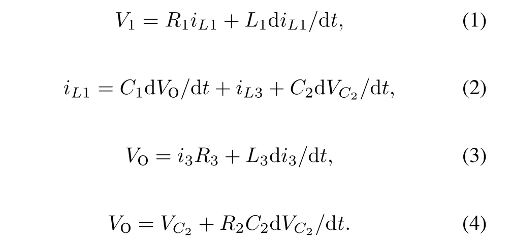
From Eqs.(1)–(4),the state equation can be obtained:
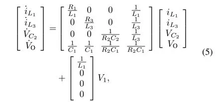

where,V2=E(t2−t1)/(t2+t1),t1andt2are conducting time ofT1andT4,andT2andT3,respectively,within one time period.
III.ESTABLISHMENT OF PREDICTIVE CONTROL MODEL
The overall MPC control structure is shown in Fig.2.A predictive model is designed to forecast a prospective outputyp(n+1).As the predictive model is not the real model,so the outputyp(n+1)is modi fi ed to get the fi nal prospective outputypr(n+1),from the real model outputy(n).Then an optimization is performed to minimize a cost function of the tracking error and the fi nale inputu(n)is obtained.At every new sampling period,the measured real output modi fi es the forecasted output on the basis of the predictive model.Then, a new round of optimization follows,and this forms a closeloop control[13–20].
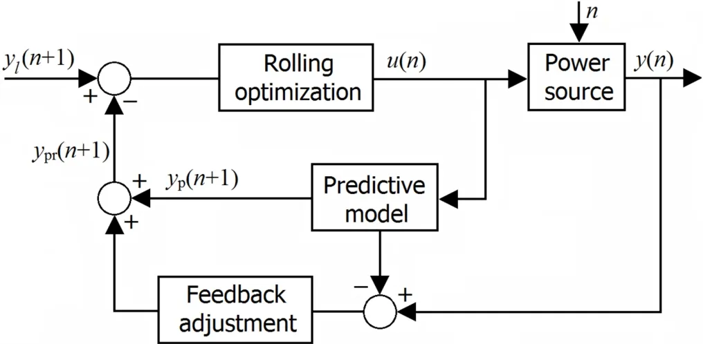
Fig.2.Structure of MPC.
A.The predictive control model
The predictive control model forecasts the subsequent output of the system on basis of the actual output just measured and the future time inputted.Any kind of model having some features of the system can be used as predictive model.In this paper,the predictive model is state equation of the power source.The discrete state equations can be described as:
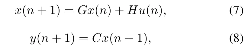
whereG=I+AT,andH=BT.Iis the identity matrix,Tis the sample period.A,B,Cis state matrix,input matrix and output matrix of the system’s state equation,respectively. Then,the predictive output in timen+1 can be obtained:

wherex(n)andu(n)are state variables and input atntime.
B.Feedback adjustment and rolling optimization
In the MPC,feedback adjustment and rolling optimization are required.Since the predictive model is not the real model, so its outputypr(n+1)need to be justi fi ed by the errore(n) of the actual output from the last predictive output
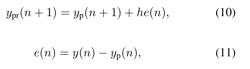
wherey(n)andyp(n)are the actual output and predictive output ofntime,respectively;andhis error correction coef ficient(h=1).This feedback adjustment makes the predictive model more assimilate to the real model.
C.The rolling optimization
The purpose of predictive control is to make the system output trace the ideal output as quickly and closely as possible.So the control objective is to minimize the sum of square errors of the prospective value from the given value.The input,however,should not be too large.Thus,the quadratic performance expression is:
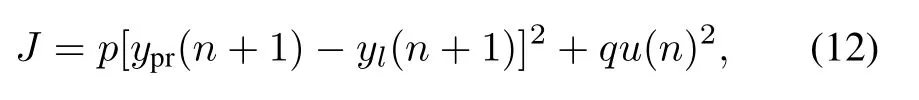
wherepandqare weighting coef fi cients.It shows that as the process goes on,the optimum varies on line.So this optimization relates only to dynamic performance of the system.
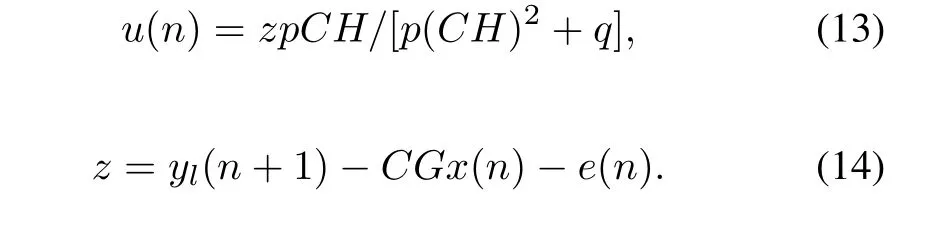
To minimize the objective function,the derivative ofJshould be equal to zero and then the control value is:
IV.SIMULATION AND EXPERIMENTAL RESULTS
Based on the model in Fig.1,a simulation was performed with Matlab.Speci fi cations of that model are:L1=0.3mH,R1=0.01Ω,L3=91.4mH,R3=0.0796Ω,C1=10µF,C2=47µF,andR2=1Ω.The sampling frequency is 10kHz,and the total simulating time is 10s.As shown in Fig.2,noise(n)of different frequencies was added to the power source to check their in fl uence on the controlled object.The results are given in Figs.3 and 4
Six simulations were performed with two kinds of input: ramp input(Fig.3)and sine input(Fig.4).The noise added to the system was in sine wave.In order to fi nd how different noises affect the output,two kinds of frequency were included:high and low.The speci fi c input and noise for each simulation are given in Table 1,wherenlowstands for low frequency noise andnhigh,high.

Fig.3.(Color online)Output of ramp input with(a)low frequency noise,(b)low frequency+30Hz noises,and(c)low frequency+100Hz noises.
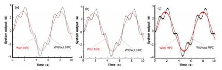
Fig.4.(Color online)Output of sine input with low frequency noise.
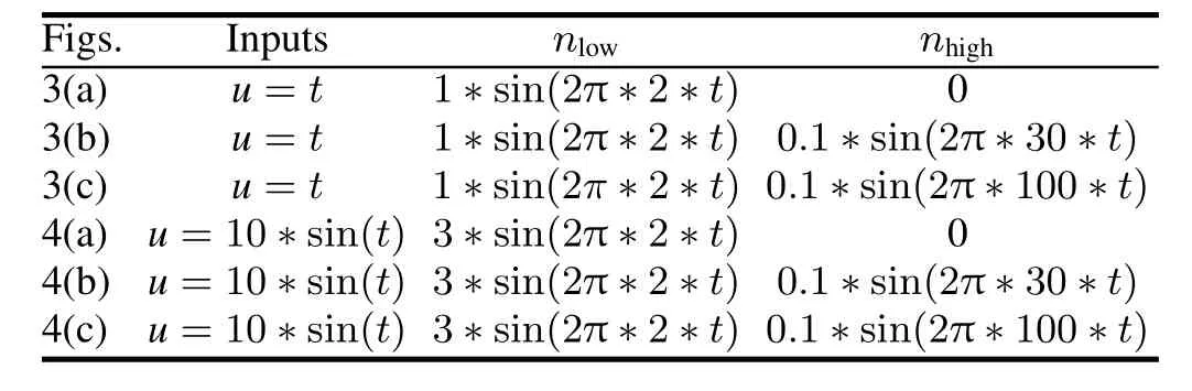
TABLE 1.The input and noise speci fi cation of the simulation
In Figs.3 and 4,the red curves are system output controlled by MPC,and the black curves are without the MPC.TheX-axis is the time and theY-axis is the system’s output of corresponding input.
In Fig.3(a),the input is in ramp wave.Compared to the red curve,the black one re fl ects the in fl uence of the noise on the output.In fact the red curve is also the ideal output that has no disturbance on the system.So it is clear the MPC diminished the noise in fl uence.In Fig.3(b),in addition to the same input and noise as in Fig.3(a),a 30Hz noise was added to the system.We can see the red one is much more close to the ideal curve than the black one.This is because that the in fl uence of low frequency noise was greatly reduced by MPC.However,comparing to the ideal output in Fig.3(a), there are ripple waves in the red curve,caused by the 30Hz noise.In Fig.3(c),the added is noise which is even higher (100Hz),and bigger ripple waves are seen.So,the MPC decreases in fl uence of low frequency noise greatly but it can do little against higher frequency noises.

Fig.5.The speci fi cation of the power source.
In Fig.4,the input is sine wave.The red curve in Fig.4(a) is the ideal output without the disturbance in the input.From Figs.4(b)and Fig.4(c)the red curves are much more similar to the ideal one than the black ones,but there are ripples,too,at noises of higher frequencies.The MPC works against low frequency noise of sine wave.

Fig.6.Experimental results without(a)and with(b)MPC.
A real model with speci fi cations shown in Fig.5 was made. Fig.5 differs from Fig.1 in that there is resistance for the capacity and inductance in the real model.Hardware implementation that actualized the proposed method was achieved by using GX-SOC/SOPC-CIDE simulator box.The system input was sine waveform with some regular noise of different frequencies.Fig.6 shows the experimental output waveform without and with the MPC.One sees that the curve in Fig.6(b)is more similar to the standard sine wave than that is in Fig.6(a),because of the noise reduction by the MPC. Therefore,the proposed control strategy is validated.
V.CONCLUSION
A real object to be controlled is much more complicated than the theoretical model.Because of unexpected disturbance,inaccuracy of components and computational delay, the real output differs with the ideal output.This problem must be taken into account in design of the controller algorithm to improve its performance and robustness.In this paper,we present an MPC method to reduce errors of the real output from the ideal output,and obtain a quick and accuracy respond for the power source that used in the particle accelerators.
Unlike conventional control theories,MPC can forecast the output according to information of both the future reference input and the last output.By optimally determining the future input on every sampling period,the proposed method can adjust the input in advance to diminish in fl uence of the unexpected factors as much as possible,so that the real output can trace the ideal output closely.The control strategy employs the state equation as the predictive model,and noises of different frequency are added to the system to search the impact of the MPC on the system.The proposed control scheme is simple and computationally ef fi cient,requiring just a few operations.The results of simulations and experiments show improvement on reduction of the noise in fl uence.
[1]Chen Y X,Yan H B,Huang Y Z.High Pow Laser Part Beams, 2010,9:2138–2142.(in Chinese)
[2]Xia J W,Zhan W L,Wei B W.Atom Energ Sci Technol,2009,43:150–158.(in Chinese)
[3]Shi CF,Huang YZ,Chen YX.AtomEnergSciTechnol,2013,47:1652–1655.(in Chinese)
[4]Wang B Y and Ma X L.Pow Electron,2010,2:67–69.(in Chinese)
[5]Wang R K,Huang Y Z,Chen Y X.Nucl Electron Detec Tech, 2013,33:558–561.(in Chinese)
[6]Huang Y Z,Chen Y X,Zhou Z Z.Nucl Phys Rev,2011,28: 296–299.(in Chinese)
[7]WangBY.Ph.D.Thesis,TianjinUniversity,2006.(inChinese)
[8]Wang Z P,Xie Y X,Wang Y.Auto Inf Eng,2013,34:34–40. (in Chinese)
[9]Liu Y,Wang H Q,Li P.Cont Theory App,2009,26:107–110. (in Chinese)
[10]Morel F,Lin-Shi X,R´etif J M,et al.Electric Pow Syst Res, 2008,78:1437–1447.
[11]Grimble C J and Ordys A W.Annu Rev Control,2001,25: 13–24.
[12]Bleris L G,Garcia J,Kothare M V,et al.J Process Contr,2006,16:255–264.
[13]Wang X G,Xie Y X,Shuai D X.J South China Univ Tech, 2009,11:56–63.(in Chinese)
[14]Xu Z L and Luo C F.Pow Syst Protect contl,2009,37:83–86. (in Chinese)
[15]Errouissi R and Ouhrouche M.Math Comput Simulat,2010,81:394–406.
[16]Bleris L G,Garcia J,Kothare M V.J Process Contr,2006,16: 255–264.
[17]Kasserm A M.Electrical Power and Energy Systems,2012,41: 124–132.
[18]Blanco E,Prada C,Cristea S,et al.Control Eng Pract,2009,17:1136–1147.
[19]Wang S B,Li C W,Gong W.Contr Instrum Chem Indust,2010,31:85–88.(in Chinese)
[20]Boua fi a A,Gaubert J,Krim F.Energ Convers Manage,2010,51:2473–2481.
10.13538/j.1001-8042/nst.25.050203
(Received November 15,2013;accepted in revised form June 27,2014;published online September 25,2014)
∗Supported by National Natural Science Foundation of China(No. 11027508)
†Corresponding author,qianxp@lzu.edu.cn
猜你喜欢
杂志排行

Nuclear Science and Techniques的其它文章
- Dose rate distribution of photoneutrons in an ID beamline of SSRF:simulations and measurements
- Calibration method for electrode gains in an axially symmetric stripline BPM∗
- A study of quasi-absolute method in photon activation analysis∗
- High-resolution boosted reconstruction of γ-ray spectra∗
- A fractionation model based on three lognormal particle size distributions
- Biological characteristics of[18F]-THK523 for tau imaging∗