High Resolution Ship Hydrodynamics Simulations in Open Source Environment
2014-07-24NormanDelPuppo
Norman Del Puppo
Department of Engineering and Architecture, University of Trieste, Trieste 34100, Italy
High Resolution Ship Hydrodynamics Simulations in Open Source Environment
Norman Del Puppo*
Department of Engineering and Architecture, University of Trieste, Trieste 34100, Italy
The numerical simulation of wake and free-surface flow around ships is a complex topic that involves multiple tasks: the generation of an optimal computational grid and the development of numerical algorithms capable to predict the flow field around a hull. In this paper, a numerical framework is developed aimed at high-resolution CFD simulations of turbulent, free-surface flows around ship hulls. The framework consists in the concatenation of“tools”, partly available in the open-source finite volume library OpenFOAM®. A novel, flexible mesh-generation algorithm is presented, capable of producing high-quality computational grids for free-surface ship hydrodynamics. The numerical frame work is used to solve some benchmark problems, providing results that are in excellent agreement with the experimental measures.
ship hydrodynamics; high-resolution simulation; grid generation; free-surface; turbulence, OpenFOAM®
1 Introduction1
The accurate numerical simulation of the free-surface flow around ship hulls requires two fundamentals right: the generation of an optimal computational grid fitted around the hull and the free-surface; the development and use of numerical algorithms capable of accurately resolving the flow field around the hull. While these requisites have been available for the last decade in most of commercial solvers, development of appropriate meshing and simulation methods in freely available CFD packages such as OpenFOAM® (Weller et al., 1998) has been ongoing.
Paterson et al. (2009) present a Wigley hull and a DTMB naval combatant free surface simulations carried out using the OpenFOAM® solver interFoam (Rusche, 2002; Berberović et al., 2009) capable of simulating free-surface flows by a volume-of-fluid (VOF) approach (Hirt and Nichols, 1981; Brackbill et al., 1992). The hexahedral grids used in the reported simulations are generated using the commercial grid generator Pointwise®. Although the wave field is accurately reproduced, the authors claim that the computational efficiency must be significantly improved for practical calculations.
Kim et al. (2010) develop and validate a ship hydrodynamic CFD library implemented in OpenFOAM®. The OpenFOAM® library is substantially modified to: a) upgrade the original turbulence models, b) to add new high-order interface-capturing methods and c) a new free-surface transient solver based on an iterative implicit solution algorithm. The computational grids are built by using either the OpenFOAM® hexahedral-dominant grid generator snappyHexMesh or the hybrid unstructured grid generator SolidMesh for double-model simulations, while the commercial package GridPro® is preferred for the free surface simulations as it provides high-quality hexahedral grids. The authors claim that “the multiphase RANS approach based on the volume-of-fluid method, when used on meshes with adequate resolution and accurate 2nd-order numeric’s, can predict most of the salient features of turbulent free-surface flows around surface ships with a remarkably good accuracy”.
Lombardi (2012) develops and validates an OpenFOAM®-based CFD framework aimed at the prediction of sailing-yacht performance, where the hull hydrodynamics can be simulated in fixed as well in free trim and sink conditions. To this end, Lombardi (2012) integrates a level-set formulation in the OpenFOAM® library as an alternative to the VOF algorithm used for interfacecapturing in free-surface simulations. The results of numerical simulations are compared to experimental and reference data obtained with the OpenFOAM® library and the commercial CFD package Ansys CFX®. Computational grids were generated with Ansys ICEM CFD® and snappyHexMesh. According to the author, Ansys CFX® provides more accurate simulations at high Froude number while OpenFOAM® yields more accurate results at low Froude numbers. Lombardi (2012) also points out that snappyHexMesh allows for localized grid refinements which can result in bad-quality elements or even invalid.
Park et al. (2013) develop a wall-function library in OpenFOAM® aimed at improving the accuracy of the ship wake-field prediction in double-model conditions. Simulations are carried out with the developed library for the KCS container ship. The computational grid is produced by the commercial grid generator Gridgen®. The obtained simulation results are compared with those obtained with the commercial CFD solver Fluent®. OpenFOAM® shows nearly the same results as Fluent® proving to be analternative to commercial CFD codes for the prediction of ship resistance performance.
Lee (2013) presents a comparison between the results obtained using the commercial packages Fluent® and Star-CCM+® and those obtained with the OpenFOAM® solver LTSInterFoam. The benchmark used is the free-surface flow around the KCS container ship. Computational grids are either unstructured produced by Star-CCM+® or block-structured hexahedral generated by the commercial grid generator Pointwise®. The numerical results obtained with the OpenFOAM® solver are in excellent agreement with the experimental data and the solver is deemed to be fast enough to be used in a production environment.
In all presented work so far, effort was focused on the numerical method. While the OpenFOAM® libraries are able in principle to produce accurate simulations results when the computational grid is appropriate to resolve all features of free-surface flow around ship hulls, the standard OpenFOAM® tools (such as snappyHexMesh) still fails to deliver the grid quality required for this kind of flow and this task is often left to commercial packages which still involve a fair amount of manual input.
The novelty of this work is to show that:
1) It is possible to achieve automatically a computational grid which is fitted for free-surface simulations. To this end, the implementation of an innovative algorithm in OpenFOAM® is described, for which a high-quality grid with 100% prism-layer coverage is obtained.
2) With additional improvements of the numerical methods used in the standard OpenFOAM® libraries, a very good agreement with experimental data in terms of flow field and forces can be achieved.
2 Grid generation
The OpenFOAM® library comes with automatic and parallelized mesh generation software: snappyHexMesh (Jackson, 2012). snappyHexMesh allows to generate a volumetric, hexahedron-dominant, unstructured mesh obtained after projection and intersection of an hexahedral volume grid onto a triangulated surface, provided in either STL or OBJ format. The volume grid used for projection starts from a hexahedral grid which is refined iteratively up to a prescribed refinement level close to the triangulated surface. The starting grid is generally a coarse, uniform cartesian mesh usually generated by the OpenFOAM® blockMesh utility. The standard final step in the grid generation process of snappyHexMesh is the addition of prism layers close to solid walls. This phase is generally critical in regions where the geometry presents corners or feature edges, or where the surface curvature changes rapidly, making the layers irregular or even collapse, resulting in poor mesh quality and/or poor flow-gradient resolution in wall vicinity. Additionally, the iterative refinement is isotropic, i.e. all control volumes are subdivided equally in all directions at each refinement step. This feature may be fine for most applications but for free-surface simulations, refinement along in the directions parallel to the free-surface only is mandatory to capture accurately the free-surface position when using a VOF method.
2.1 marineSnappyHexMesh tool for mesh generation
In the following, a modified version of the snappyHexMesh utility will be described and will be denoted by marineSnappyHexMesh hereafter. This application allows the generation of high quality computational grids with 100% cell layers coverage on solid walls. Contrary to the standard approach of snappyHexMesh, the user-specified cell layer coverage is obtained using a surface inflation approach followed by a grid-extrusion. An optional anisotropic grid refinement in the free-surface region is available. Finally, after completion of the above steps, a trapezoidal searchable surface is used and added to the runtime refinement selectable geometric entities to refine the mesh further in order to capture the wave pattern generated by the hull slicing through water.
2.1.1 Cell layers on solid walls generation
snappyHexMesh generates a computational grid projecting a refined-castellated grid onto a triangulated surface representing the boundary of the computational domain. A triangulated surface is represented in OpenFOAM® code by the C++ class triSurfaceMesh. A triSurfaceMesh is used to:
1) Read and write a triangulated surface in STL format 2) Check, scale and transform the surface 3) Compute vertices and faces connectivity
4) Compute triangles vertices and faces normals
The procedure from the standard snappyHexMesh tool implemented to generate cell layers on solid walls is generally critical and can lead to unexpected results. In this work a novel algorithm is implemented using a new OpenFOAM® triangulated surface type, hereafter called triSurfaceInflatedMesh (see Appendix C), capable of solving the problem of the generation of near-wall cell layers on ship’s walls. Starting from a watertight triangulated surface, the proposed method is based on:
1) Compute the local inflation directions using the triangles (face and vertex) normals.
2) Extrude the triangulated surface along the computed directions to the desired layer thickness.
3) Project and intersect the castellated volume grid on the inflated triangulated surface (standard snappyHexMesh step).
4) For each boundary vertex find the nearest triangle on the triangulated surface. Compute the extrusion direction as an average of the triangle vertex normals.
5) Insert a layer of cells to fill the gap between the original and the inflated triangulated surface by grid extrusion.2.1.2 Interface anisotropic refinement
In free-surface simulations it is common to perform an anisotropic refinement along the direction parallel to the free-surface in order to better capture the interface position minimizing at the same time the number of cells generated for this purpose. An optional anisotropic grid refinement procedure is added to marineSnappyHexMesh using the OpenFOAM® multiDirRefinement mesh manipulation object. The multiDirRefinement mesh manipulation is an OpenFOAM® C++ object capable of doing multiple pass refinement on a cells set along a given direction. The anisotropic grid refinement takes place at the end of the first standard snappyHexMesh step, namely the castellated grid generation (Fig. 1). The proposed iterative method identifies those cells that are within a user-specified refinement region and have a refinement level contained in a user-assigned range. Subsequently these cells are split vertically using the OpenFOAM® multiDirRefinement object and the refinement levels are upgraded. The procedure is repeated until all the cells contained in the anisotropic refinement region violate the refinement criteria.
The advantages of this procedure are two-fold: the grid is refined only vertically and the cells that have already a satisfactory level of refinement are not over-refined.
2.1.3 Trapezoidal searchable surface
A trapezoidal searchable surface is developed and added to the runtime refinement selectable geometric entities to refine the hull wave region minimizing at the same time the number of cells generated. The implemented searchable surface is based on the polywind algorithm (Press et al., 2007), used to determine if a cell centre is contained in a parametric trapezoidal box to mark a cell for refinement during the castellated grid generation step.
2.2 Overview of the mesh-generation process
In summary, marineSnappyHexMesh generates a computational grid by going through the following steps (Fig. 1 and Fig. 2):
1) Read a triangulated surface representing the boundary of the computational domain.
2) Inflate the triangulated surface using the algorithm stated above (Fig. 3(a)).
3) Generate a castellated mesh that approximates the computational domain by means of refined hexahedral cells (standard snappyHexMesh step) (Fig. 3(b)).
4) Refine anisotropically the castellated mesh along the vertical direction in the free surface region (optional) (Fig. 3(c)).
5) Snap the castellated mesh to the given triangulated surface (standard snappyHexMesh step) (Fig. 3(d)).
6) Generate the specified number of cell layers extruding and projecting the surface grid on the inflated triangulated surface (Fig. 3(e)).
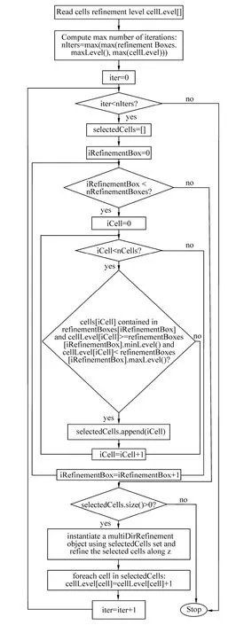
Fig. 1 marineSnappyHexMesh: interface anisotropic refinement
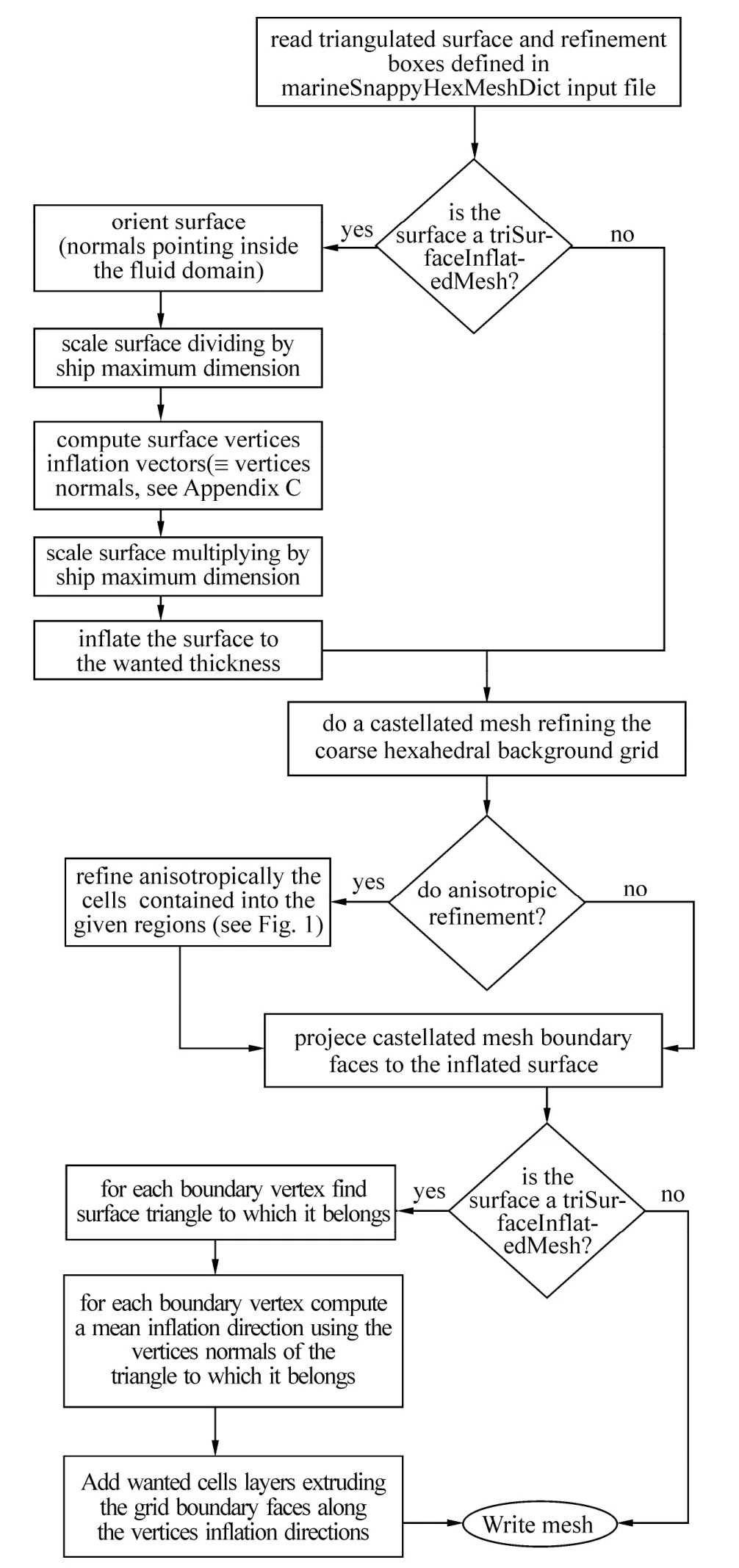
Fig. 2 marineSnappyHexMesh: grid generation procedure

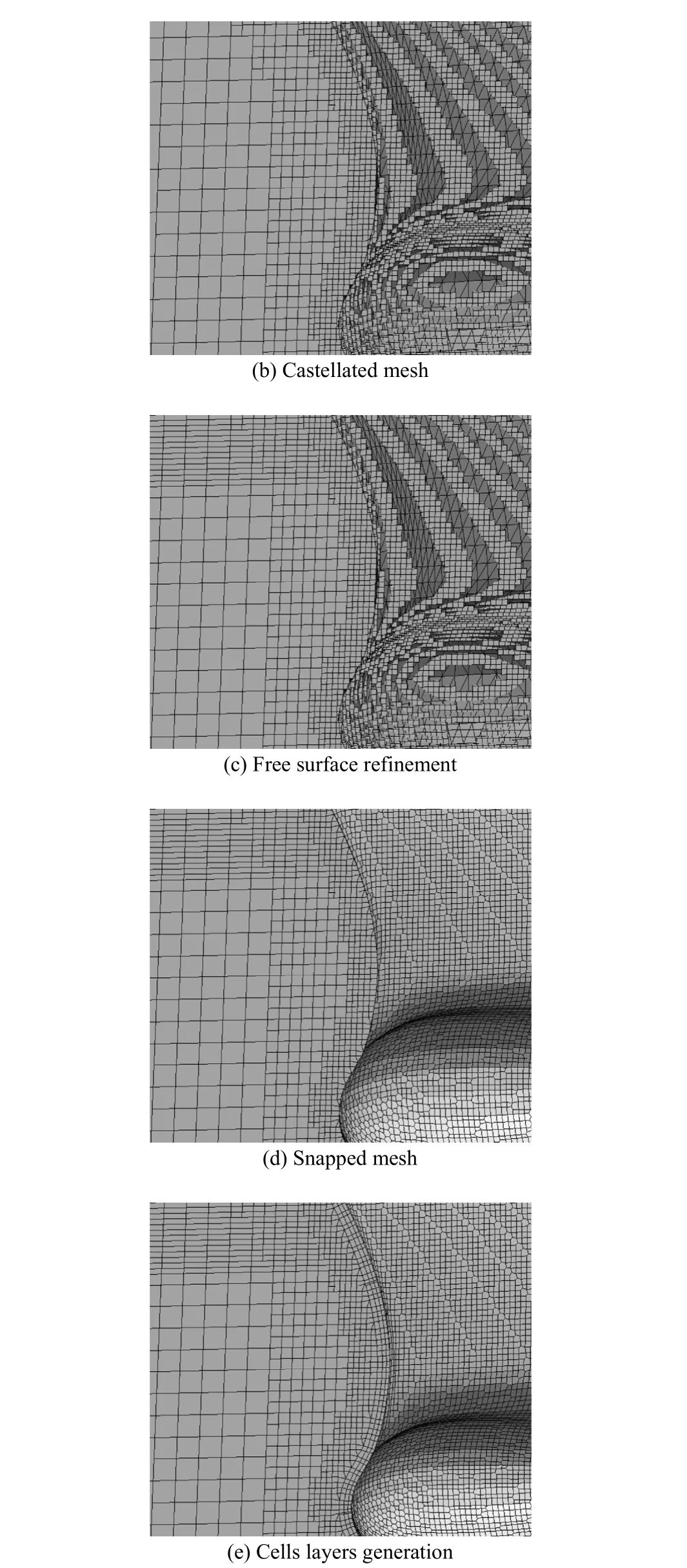
Fig. 3 marineSnappyHexMesh: DTMB 5512 hull grid generation, bow detail
3 Numerical method
3.1 Double-model simulations
The flow field around a hull double model configuration is simulated using the simpleFoam solver, which is part of theOpenFOAM® software suite. This solver is designed for incompressible single-phase flows. The governing equations are the incompressible Reynolds-averaged Navier-Stokes equations

where U is the velocity field,pthe kinematic pressure

and

is the viscous stress term with an effective kinematic viscosity υeff, taking into account both the molecular viscosity and the turbulence mixing.
3.2 Free-surface simulations
The free surface simulations in calm water, fixed trim and sink conditions are carried out by means of the OpenFOAM® solver LTSInterFoam, where the flow is considered to be incompressible and isothermal. Both fluid phases, water and air, are assumed to be immiscible fluids. The interface between both fluids are simulated using a volume of fluid approach (VOF hereafter).
The fluid density ρ(α) and viscosity μ(α) depend on the volume fraction ()xα

The distribution ofα(x) is modelled by an advection equation

similar to the Volume of Fluid method described in Hirt and Nichols (1981). The last term on the left-hand side is a compression term introduced to limit the smearing of the interface (Rusche, 2002, Berberović et al., 2009).rU is a relative velocity defined by

where φ is the face volume flux, cαis a user-defined coefficient (usually 0≤cα≤2) used to control the effect of the compression term,is the cell-face area vector andis a term inversely proportional to the cell size defined as

The following Reynolds-averaged Navier-Stokes equations are solvedZ


where U is the velocity field, α is the volume fraction of water in the computational cells, ρis the density,

wherep*is the pressure from which the hydrostatic contribution is removed, g is the gravitational acceleration vector and x is the Cartesian coordinates vector,

is the viscous stress term with an effective dynamic viscosity

is the gravitational term,

represents the surface tension body force, where σTis the surface tension coefficient and καis the mean curvature of the free surface. In this work it is assumed σT=0 considering the effects of the surface tension negligible (We=9.8×10⁴).
Different turbulence models are used in the reported simulations, namely the Menter k-ω SST (Menter et al., 2003) and the Wilcox k-ω 1988 (Wilcox, 1988) closure models already provided in OpenFOAM® as well as a Wilcox k-ω 1998 (Wilcox, 1998) turbulence model implemented in the proposed add-on library.
4 Results
The Gothenburg 2010 Workshop on Numerical Ship Hydrodynamics (Larsson et al., 2010) 1.1a and 3.1b benchmark cases are used to validate the grid generator and the numerical library implemented in OpenFOAM®. The numerical results obtained for the two cases are presented in the following sections and compared to the experimental measures.
4.1 KVLCC2 benchmark–Validation of turbulence model
The flow around the KVLCC2 bare hull with the Reynolds number of Re=4.6×10⁶is simulated under double-body flow assumptions. The wake field is computed using the steady state solver for incompressible fluids simpleFoam included in OpenFOAM®. The OpenFOAM® cellLimited Gauss linear scheme is used to compute the gradients, while the convective terms are discretized using the second order upwind scheme linearUpwind. Turbulence is modelled using the Menter k-ω SST, Wilcox k-ω 1988 (Wilcox, 1988) and Wilcox k-ω 1998 (Wilcox, 1998) turbulence models. Two mixed hexahedral-polyhedral computational grids with 3.3 million and 5.3 millions of cells are generated using marineSnappyHexMesh to check the solution grid independence. The grids are generated fory+=40 in order to use the wall function approach to set the boundary conditions for the turbulence models (Fig. 4). Due to geometry symmetry, only half domain is simulated with symmetry conditions.
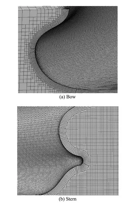
Fig. 4 KVLCC2 3.3 millions of elements grid details
A comparison of the dimensionless axial velocity field between the CFD results obtained for the considered turbulence models and the experimental data is shown in Fig. 5.
The numerical results are in excellent agreement with the experimental measures for the case simulated using the implemented Wilcox k-ω 1998 turbulence model for which the characteristic hook-shape of the velocity contours is well captured (Kim and Rhee, 2002).
4.2 DTMB 5512 benchmark–free-surface simulation
The DTMB 5512 hull model with the Froude number of 0.28 is simulated in calm water under fixed sink and trim conditions.
Two computational grids composed of 3.7×10⁶and 7.7×10⁶polyhedral cells are generated using marineSnappyHexMesh. The near-wall cell thickness is approximately y+=40 with an anisotropic refinement around the expected position of the free-surface (Fig. 6). The region around the expected development of wave pattern region is also isotropically refined employing the implemented trapezoidal searchable surface. Due to geometry symmetry, only half of the domain is simulated.
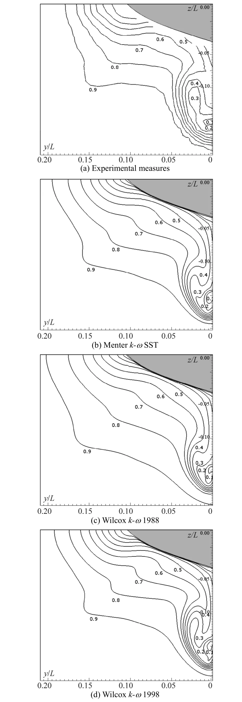
Fig. 5 KVLCC2, dimensionless axial velocity field (Ux/U∞)
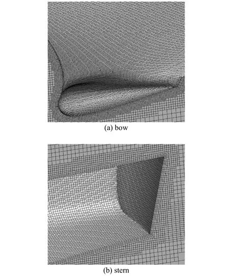
Fig. 6 DTMB 5512 3.7 millions of elements grid details
The solution is computed using the standard OpenFOAM® multi-phase solver LTSInterFoam. The simulations are carried out using different interpolation schemes. In details, the linearUpwind second order scheme is applied to discretize the convection terms; the standard vanLeer and the implemented HRIC (Muzaferija and Peric, 1999) schemes are used to solve the volume fraction equation; the diffusion term is discretized by a second-order central difference scheme. The PISO algorithm is employed for pressure-velocity coupling applying one prediction and two correction steps. The Menter k-ω SST and Wilcox k-ω 1998 models are used as turbulence closures.
The total resistance coefficient computed by different methods and on different meshes using the equation:

is compared in Table 1. In Eq. (16),andare the pressure and the viscous forces including the effects of air, S is the hull wetted surface area, U∞is the hull speed and ρ is the fluid density.
The comparison shows the HRIC scheme behaves better than the vanLeer scheme usually employed in OpenFOAM® for free surface simulations. The Menter k-ω SST turbulence model is, in this case, to be preferred to the Wilcox k-ω 1998.
The numerical results for the fine grid are also compared to the experimental measures for the wave pattern in Fig. 7 and the dimensionless axial velocity at x/L=0.935 in Fig. 8. The wave pattern numerical results are in an excellent agreement with the experimental measures. The comparison of the dimensionless axial velocity field shows that both the turbulence models are capable to predict the global features of the boundary layer.
The comparison of the computational time (Table 2) and the resistance force history (Fig. 9) show the HRIC scheme improves the solution stability and reduces the computational efforts needed to reach a stable solution.
The simulation results computed using the implemented tools for the coarse grid are finally compared to a numerical simulation realized using the standard OpenFOAM® algorithms for a grid of a comparable size (4.2×10⁶cells) generated employing snappyHexMesh with the same refinement regions layout.
The two CFD simulations are compared to the experimental measures for a set of wave cuts (Fig. 10). The numerical results produced using the developed methods are in an excellent agreement with the experimental measures compared to the standard simulation.
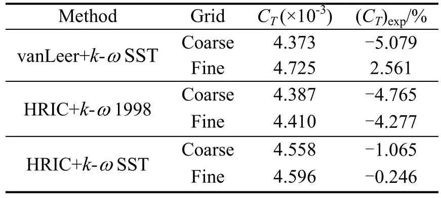
Table 1 Grid independence study, experimentally measured CT=4.607×10⁻³
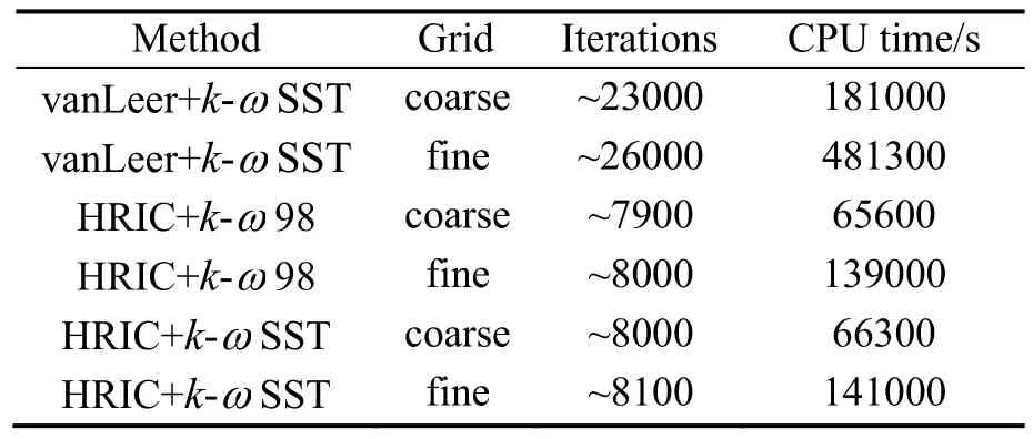
Table 2 Convergence details. Domains decomposed in 12 parts. Simulations run on a dual Xeon E5-2630 2.30 GHz
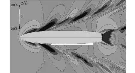
Fig. 7 DTMB 5512 7.7 millions of elements grid, Wilcox k-ω SST+HRIC (top) vs. experimental measures (bottom)

Fig. 8 DTMB 5512 dimensionless axial velocity field (Ux/U∞)

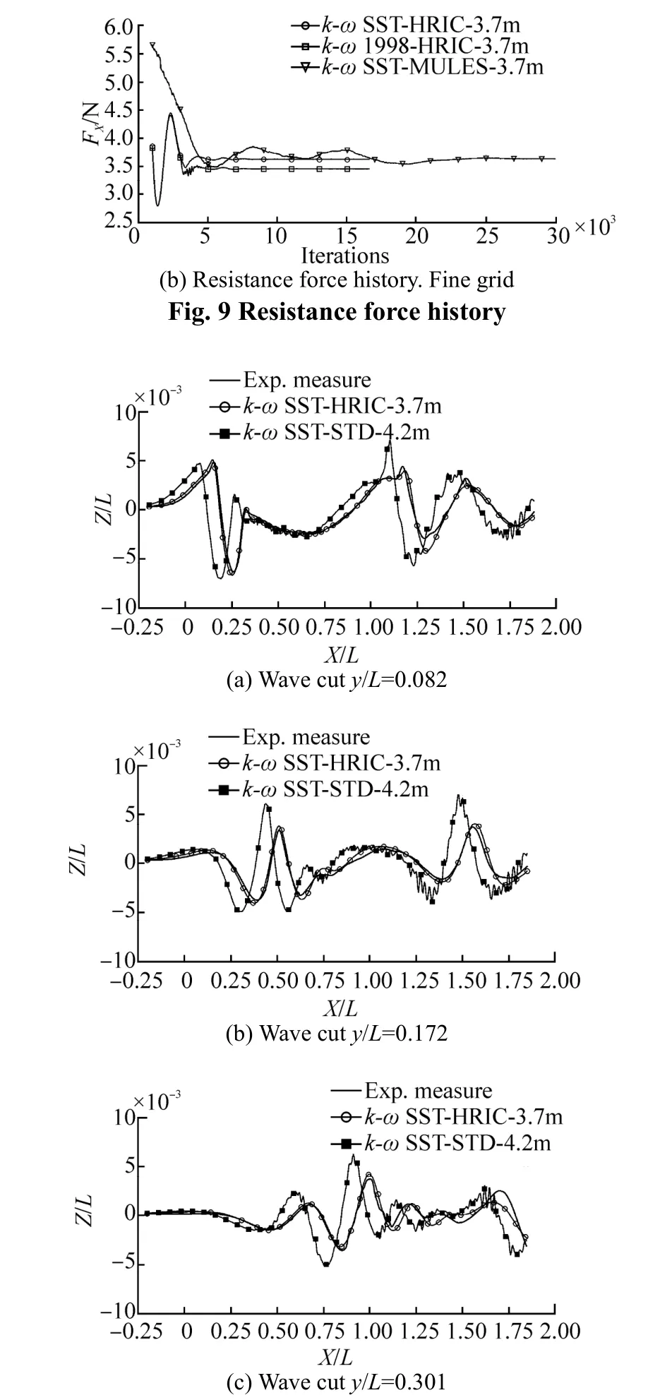
Fig. 10 DTMB 5512 wave elevation along three longitudinal cuts
5 Conclusions
A numerical framework and a novel grid generator tailored for ship hydrodynamics applications and based on the open source library OpenFOAM® are introduced. The presented toolbox is validated simulating two cases taken from the Gothenburg 2010 Workshop on Numerical Ship Hydrodynamics benchmarks: the flow around the KVLCC2 bare hull under double-body-flow assumptions and the DTMB 5512 hull model free surface simulation in calm water, fixed trim and sinkage conditions. The numerical results compared to the experimental measures demonstrate that the implemented library in OpenFOAM® is capable of predict the flow around a hull ship with a remarkable goodaccuracy making the proposed numerical framework a reliable toolbox to be employed in practical ship hydrodynamics applications.
Berberović E, van Hinsberg NP, Jakirlić S, Roisman IV, Tropea C (2009). Drop impact onto a liquid layer of finite thickness: Dynamics of the cavity evolution. Physical Review E, 79, 036306.
Brackbill JU, Kothe DB, Zemach C (1992). A continuum method for modeling surface tension. Journal of Computational Physics, 100, 335-354.
Hirt C, Nichols B (1981). Volume of fluid (VOF) method for the dynamic of free boundaries. Journal of Computational Physics, 39, 201-225.
Jackson A (2012). A comprehensive tour of snappyHexMesh. 7th OpenFOAM Workshop Lecture, Darmstadt.
Kim SE, Rhee BJ, Shan H, Gorski J, Paterson EG, Maki K (2010). A scalable multiphase ranse capability based on object-oriented programming and its applications to ship hydrodynamics. Gothenburg 2010 a Workshop on Numerical Ship Hydrodynamics, Gothenburg, 629-634.
Kim SE, Rhee SH (2002). Assessment of eight turbulence models for a three-dimensional boundary layer involving cross-flow and streamwise vortices. 40thAIAA Aerospace Sciences Meeting and Exhibit, Reno, Nevada, USA, AIAA Paper 2002-0852.
Larsson L, Stern F, Visonneau M (2010). Numerical ship hydrodynamics. Gothenburg 2010 a Workshop on Numerical Ship Hydrodynamics, Gothenburg, 1-32.
Lee SB (2013). Practical application of openfoam to prediction of hull resistance. 8th OpenFOAM Workshop Lecture, Jeju.
Lombardi M (2012). Numerical simulation of a sailing boat: free surface, fluid structure interaction and shape optimization. PhD thesis, École Polytechnique Fédérale de Lausanne, Lausanne, 25-66.
Menter F, Kuntz M, Langtry R (2003). Ten years of industrial experience with the SST turbulence model. Turbulence, Heat and Mass Transfer 4: Proceedings of the Fourth International Symposium on Turbulence, Heat and Mass Transfer, Antalya, 625-632.
Muzaferija S, Peric M (1999). Nonlinear water wave interaction. WIT Press, Southampton, UK, 59-100.
Park S, Park SW, Rhee SH, Lee SB, Choi JE, Kang SH (2013). Investigation on the wall function implementation for the prediction of ship resistance. International Journal of Naval Architecture and Ocean Engineering, 5, 33-46.
Paterson E, Smith K, Ford S (2009). Simulation of wakes, wave impact loads, and seakeeping using OpenFOAM. 4th OpenFOAM Workshop Lecture, Montreal.
Press WH, Teukolsky SA, Vetterling WT, Flannery BP (2007). Numerical recipes: The art of scientific computing. 3rd ed., Cambridge University Press, New York, 1117-1128.
Rusche H (2002). Computational fluid dynamics of dispersed twophase flows at high phase fraction. PhD thesis, Imperial College of Science, Technology & Medicine, Department of Mechanical Engineering, London, 147-178.
Weller HG, Tabor G, Jasak H, Fureby C (1998). A tensorial approach to computational continuum mechanics using objectoriented techniques. Computer in Physics, 12(6), 620-631.
Wilcox DC (1988). Reassessment of the scale-determining equation for advanced turbulence models. AIAA Journal, 26(11), 1299-1310.
Wilcox DC (1998). Turbulence modeling for CFD. 2nd ed., DCW Industries Inc., La Canada, CA, 84-87.
Author biography

Norman Del Puppo is presently a PhD candidate at School of Engineering and Architecture, University of Trieste. His research interests include computational ship hydrodynamics, hull form optimization and grid generation based on OpenFOAM.
Appendix A–Turbulence models equations
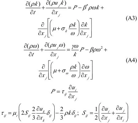
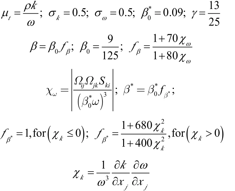
A.1 Standard Wilcox k-ω 1988 model

A.2 Standard Wilcox k-ω 1998 model
Appendix B–HRIC scheme
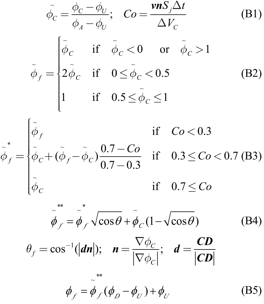
The VOF interface capturing method requires high resolution schemes to reduce numerical diffusion or numerical dispersion phenomena, a known drawback of the approach. The main task of a high resolution schemes is to discretize the convective term of the volume fraction transport equation in a way to prevent the smearing of the interface that can occur due to numerical diffusion and preserve the monotonic distribution of the variable. Muzaferija and Peric (1999) introduce the HRIC high resolution scheme in which the cell face value of the volume of fraction is computed using the following relations.

Fig. B1 Computation of the cell face volume fraction
Appendix C–triSurfaceInflateMesh
The triangulated surface inflation algorithm is implemented in a triSurfaceInflatedMesh class derived from the triSurfaceMesh OpenFOAM® C++ object.
The triSurfaceInflatedMesh is added to the callable geometric entities in marineSnappyHexMesh to define a computational grid. The triangulated surface inflation is controlled by a set of user parameters that can be tuned for each triSurfaceInflatedMesh to define the first cell size, the number of cells layers, the cells layers growing factor and to control the way the surface vertex inflation directions are generated to ensure a valid inflated triangulation.
The method implemented to inflate a triangulated surface in its full length is reported in this appendix.
Starting from a watertight triangulated surface, the inflated surface is generated by taking the following steps:
1) Orient the triangulated surface so that all the triangles face and vertex normals point inside the fluid domain. The vertex normal are computed using:
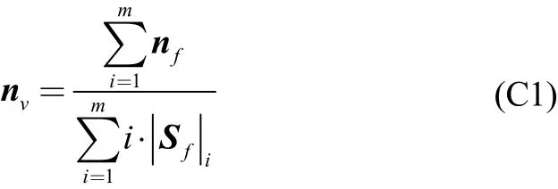
wheremis a list of triangles sharing the vertex for which the angle (dot product) formed by the face normals of the owner and the neighbour triangles is smaller than a user specified threshold value,is the triangle area and nfis the face normal. At this stage a face normal and three vertex normals are coherently defined for each triangle belonging to the triangulated surface (Fig. C1(a)).
2) Detect the hull triangulated surface edges that intersect the computational domain boundary box (unconnected free triangulation edges). Store the collected edges in a geometry boundary edges set.
3) Search for the triangulated surface internal edges (feature edges) looping on all the triangulation edges. A triangulation edge is marked as a feature edge if the angle (dot product) formed by the two face normals of the triangles sharing the edge in exam is smaller than a user specified threshold value. If the edge is a feature edge, it is also computed the dot product of one of the two triangles face normal and the triangle face centres vector. If the dot product is positive, the feature edge is marked as an inward pointing feature edge (i.e. fin root edges), if negative it is marked as an outward point feature edge (i.e. transom edges). The feature edges are finally saved in a feature edges set.
4) Detect the vertices topology. Loop on all the triangles in the triangulated surface. Loop on the triangle vertices. If a vertex belongs to a single feature edge, mark it as an inward/outward feature point, depending on the topology of the feature edge. If the vertex belongs to multiple feature edges, mark it as a corner vertex. If the vertex doesn’t belong to a feature edge then mark it as a simple internal vertex.
5) Compute the triangulated surface vertex inflation direction using the triangle-face and vertex-normals:
(a) Initialize the inflation directions. Loop on all the triangles. For each triangle (owner), loop on the triangle’s vertices. Next, obtain a list of all the neighbour triangles sharing the vertex in the exam. Compute the dot product between the face normal of the owner and the neighbour triangles. If the dot product is smaller than the user specified feature edge angle (see step 3)), then save the area and the face normal of the neighbour triangle in the list. Compute an initial vertex inflation direction for the vertex in exam:

wheremis the list of the considered neighbour triangles,is the triangle area and n is the triangle face normal.
(b) Modify the inflation direction vector for the triangle vertices belonging to a feature edge. Loop on all the triangulated surface vertices belonging to a feature edge. Loop on the triangles sharing the vertex in exam. Add the triangles face normal to a set of unique face normals. Compute a new vertex inflation direction summing the normals in the set and dividing by the number of the normal contained in the set. Normalize the inflation direction vector. Assign the computed inflation direction to the vertex in exam. At this point the inflation direction vectors are univocally defined for each triangulated surface vertex (Fig. C1(b)).
(c) Modify the inflation direction for those vertices belonging to a geometry boundary edge projecting the vertices inflation direction vectors on the computational domain plane the triangulation intersects. Normalize the inflation directions (Fig. C1(c)).
(d) Smooth the vertex inflation directions for those vertices that stay within a user given smoothing distance from the computational domain boundaries computing a linearly weighted inflation direction:

(e) Smooth the vertex inflation directions for those vertices that belong to a feature edge and stay within a user given smoothing distance from a corner vertex computing a linearly weighted inflation direction using the corner inflation direction and the distance from the corner vertex. Smooth the vertex inflation directions for the remaining triangulation vertices that stay within a smoothing distance from a feature vertex. Normalize the vertex inflation directions (Fig. C1(e)).
6) Inflate the triangulated surface along the vertex inflation directions to the wanted boundary layer thickness determined by the user assigned first cell size, number of layers and growing factor parameters (Fig. C1(f)).
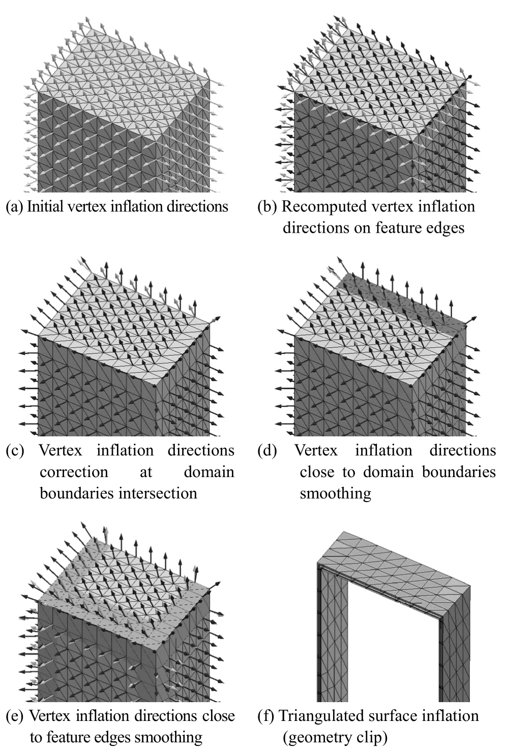
Fig. C1 Triangulated surface inflation algorithm. Current step vertex inflation directions represented in black, previous step ones in grey
1671-9433(2014)04-0377-11
J. Marine. Sci. Appl. (2014) 13: 377-387
10.1007/s11804-014-1278-2
date: 2014-06-21.
Accepted date: 2014-08-06.
*Corresponding author Email: norman.delpuppo@phd.units.it
© Harbin Engineering University and Springer-Verlag Berlin Heidelberg 2014
杂志排行
Journal of Marine Science and Application的其它文章
- Research on Energy Efficiency Design Index for Sea-going LNG Carriers
- Wave Scattering by Porous Bottom Undulation in a Two Layered Channel
- Flow Past an Accumulator Unit of an Underwater Energy Storage System: Three Touching Balloons in a Floral Configuration
- Damping of Oblique Ocean Waves by a Vertical Porous Structure Placed on a Multi-step Bottom
- Galvanic Interactions of Aluminium 3004 and ∝ Brass in Tropical Marine Atmosphere
- 34th International Conference on Ocean, Offshore and Arctic Engineering (OMAE2015)
