Superparamagnetic Supported Catalyst H3PW12O40/γ-Fe2O3for Alkylation of Thiophene with Olefine*
2014-07-24XUCuixia许翠霞YANGKedi杨克迪LIUZili刘自力QINZuzeng秦祖赠HEWei何维DAIQianwen代倩雯ZHANGJianjie张健杰andZHANGFan张帆
XU Cuixia (许翠霞), YANG Kedi (杨克迪), LIU Zili (刘自力),,, QIN Zuzeng (秦祖赠), HE Wei (何维), DAI Qianwen (代倩雯), ZHANG Jianjie (张健杰)and ZHANG Fan (张帆)
1School of Chemistry and Chemical Engineering, Guangxi University, Nanning 530004, China
2China Key Laboratory of Ministry of Education for Water Quality Security and Protection in Pearl River Delta, School of Chemistry & Chemical Engineering, Guangzhou University, Guangzhou 510006, China
3Key laboratory of Nonferrous Metal and New Processing Technology of Materials (Ministry of Education), Guangxi University, Nanning 530004, China
Superparamagnetic Supported Catalyst H3PW12O40/γ-Fe2O3for Alkylation of Thiophene with Olefine*
XU Cuixia (许翠霞)1, YANG Kedi (杨克迪)1, LIU Zili (刘自力)1,2,**, QIN Zuzeng (秦祖赠)1, HE Wei (何维)3, DAI Qianwen (代倩雯)2, ZHANG Jianjie (张健杰)2and ZHANG Fan (张帆)2
1School of Chemistry and Chemical Engineering, Guangxi University, Nanning 530004, China
2China Key Laboratory of Ministry of Education for Water Quality Security and Protection in Pearl River Delta, School of Chemistry & Chemical Engineering, Guangzhou University, Guangzhou 510006, China
3Key laboratory of Nonferrous Metal and New Processing Technology of Materials (Ministry of Education), Guangxi University, Nanning 530004, China
The alkylation of sulfur compounds with olefine is considered to be an attractive way to attain high level of sulfur removal by raising the boiling point of sulfur-containing compounds to ease their separation from light fractions by distillation. A series of superparamagnetic supported catalysts, used for alkylation of thiophene with 1-octene, were prepared by loading H3PW12O40(HPW) onto commercially available nanoparticles γ-Fe2O3through incipient wet impregnation method. The catalysts were characterized by X-ray diffraction (XRD), Fourier transform infra-red (FT-IR), thermo gravimetric analysis (TG), N2-adsorption and vibrating sample magnetometer (VSM). The physicochemical characterization reveals that γ-Fe2O3could be accommodated to immobilize and disperse HPW. Moreover, possessing high magnetization of 26.1 A·m2·kg−1and with mesoporous structure with specific surface area of 35.9 m2·g−1, the 40% (by mass) HPW loading catalyst is considered the proper catalyst for olefinic alkylation of thiophenic sulfur (OATS) and can be separated in an external magnetic field. The catalytic activity was investigated in the alkylation reaction of thiophene with 1-octene, and the conversion of thiophene is up to 46% at 160 °C in 3 h. The 40% (by mass) HPW/γ-Fe2O3catalyst can be reused 6 times without too much loss of activity and keeps its property of superparamagnetism.
alkylation, heteropolyacid, thiophene, superparamagetism
The alkylation of thiophene and its derivatives with olefine occur through carbocation formation, for which acid catalysts are needed [8]. Previous researchers proposed many different catalysts with either Lewis or Brösted acidity, including various kinds of zeolites (HY, USY, Hβ, HMCM-22, Cu-MCM-48) [9-12], phosphoric acids (SPA-11, SPAM and SPAS) [1, 13], heteropolyacids [14, 15], and Amberlyst 35 resin [16]. Among these catalysts, heteropolyacids are more and more favored by researchers and received increasing attention as eco-friendly solid acid catalysts, due to the very strong Brösted acidity, the unique pseudo-liquid phase and multifunction [17]. Arias et al. [14] reported that silica-supported heteropolyacid is the best catalyst among the acidic catalysts of zeolites (Hβ, USY, and MCM-22), silica-supported phosphoric acid, and silica-supported HPW and 12-silicotungstic (HSiW) acids for the alkylation of 3-methylthiophene with 2-methyl-2-butene.
In our group, the supported Keggin-type H3PW12O40(HPW) is chosen to study FCC gasoline desulfurization. Creating a larger surface area and enhancing the accessibility of active sites, the supported HPW provides a way to eliminate the feature of water-soluble low surface area of bulk HPW. Different types of supports have been reported, including SiO2[18], ZrO2[19], K-10 [20], and aluminophosphate molecular sieves [21]. However, these supported catalyst fine particles are needed to be molded into certain sharp before using inthe reactor that results in slowed-down mass and heat transfer, when they are used in regular reactor, such as fixed bed reactor. In addition, the catalysts are often separated through mechanical separation which is not convenient for continuous reaction and causes catalyst loss. Magnetic nanoparticles used as catalyst supports can be one of possible route to address the problems [22, 23]. Because of its characteristics of small size and superparamagetism, magnetic nanoparticles supported catalyst can be applied in Magnetic Fluidized Bed Reactor (MSFBR) and suspension catalytic distillation (SCD) in which fine catalyst particles are mixed in the liquid so as to contact sufficiently with reactants. Catalysts in these reactors also can be separated easily in an external magnetic field [24-26].
In this paper, highly magnetized nanoparticles γ-Fe2O3are chosen as the magnetic support. The catalytic activity of γ-Fe2O3-supported HPW (HPW/γ-Fe2O3), which has been fully optimized in correlation with the alkylation of thiophene with 1-octene representative of both sulfur compounds and olefine of an FCC feed, is reported. Also, the reusability of HPW/γ-Fe2O3is investigated.
2 EXPERIMENTAL
2.1 Preparation of HPW/γ-Fe2O3
Using methanol as solvent, different loading HPW/γ-Fe2O3catalysts were prepared by a typical incipient wet impregnation [14, 27]: A certain amount of 0.08 mol·L−1methanol solution of HPW was added dropwise to 5 g commercially available γ-Fe2O3(size of 20 nm) at room temperature to make a wet paste. The amounts of HPW solutions were adjusted to provide different loading levels, and the samples were dried at 110 °C overnight and calcined at 300 °C for 3 h in the flow of N2.
2.2 Characterization of HPW/γ-Fe2O3
HPW/γ-Fe2O3catalysts were characterized by XRD (Beijing Purkinje General Instrument Co., model XD-3), FT-IR (Perkin-Elmer Inc., USA, Spectrum 100), TG (TA Instruments-Waters LLC, USA, SDT Q600), and N2adsorption instrument (Micromeritics Inc., USA, ASAP 2000). Based on the adsorption branches of N2sorption isotherms, the Brunauer-Emmett-Teller (BET) method was used to calculate the specific surface area and the Barrett-Joyner-Halenda (BJH) model was used to calculate the pore volume and average pore diameter. Magnetic characterization was carried out on a VSM (Lakeshore Inc., USA, model 7410) at room temperature. Particle size was analyzed on a Zetasizer (Malvern Inc., USA, Nano ZS90).
2.3 Alkylation of thiophene with 1-octene on HPW/γ-Fe2O3
Catalytic model reaction was carried out in a 50 ml autoclave filled with 2 ml thiophene, 15 ml 1-octene, and 2 ml n-hexane used as the internal standard for the gas chromatograph (GC) analysis. Freshly calcined catalyst was added to the above mixture. The mixture was stirred at 500 r·min−1under autogenous pressure, and heated up from room temperature to 100-180 °C.
The products were analyzed by a Shimadzu GC-2014C gas chromatograph (FID, column OPTIMA-5: 30 m×0.32 mm×φ0.25 μm). The GC conditions used for analysis were: 40 °C held for 2 min, ramped to 250 °C at rate of 20 °C·min−1and then held for 2 min. Both the injection temperature and the detection temperature were 250 °C. GCMS-QP2010 Plus (Shimadzu Co., Japan) was used to identify the reaction products.
3 RESULTS AND DISCUSSION
3.1 Characterization of HPW/γ-Fe2O3catalysts
3.1.1 X-ray diffraction
XRD patterns of HPW, γ-Fe2O3and HPW/γ-Fe2O3with various loading are shown in Fig. 1. The XRD patterns of γ-Fe2O3and HPW/γ-Fe2O3show five well resolved diffraction peaks at 2θ=29.3°, 34.5°, 42.1°, 56.3° and 61.9° which are indexed to (220), (311), (400), (511) and (440) crystal planes of standard magnemite (JCPDS 39-1346). The peaks on the XRD pattern of bulk HPW at 2θ=10.2°, 25.5°, and 29.6°, which are indexed to (110), (222) and (400) crystal planes, are characteristic peaks of the Keggin structure of HPW [20]. The γ-Fe2O3support which is analysed from the N2adsorption-desorption isotherm, is mesoporous solid. When the HPW loading is very low, HPW is immobilized and dispersed inside the pores of the support, and no characteristics peak of HPW is detected. As the loading amount increases, HPW is dispersed evenly on both the inside and outside pores, more acidic sites are attained, and the characteristics peaks of HPW are observed at 2θ=25.5°. However, when the loading amount is relatively high, bulk crystals are formed in both the pore and the external surface of support. This decreases extremely the surface area of catalyst and the number of acidic sites. Thisresult is accord with the analysis of loading effect on activity of HPW/γ-Fe2O3, the studies of N2adsorption-desorption isotherm and FT-IR analysis.

Figure 1 XRD patterns of bulk HPW (a), γ-Fe2O3(b), 10% (by mass) HPW/γ-Fe2O3(c), 20% (by mass) HPW/γ-Fe2O3(d), 30% (by mass) HPW/γ-Fe2O3(e), 40% (by mass) HPW/γ-Fe2O3(f) and 50% (by mass) HPW/γ-Fe2O3(g)
3.1.2 N2absorption-desorption isotherm
Nitrogen adsorption-desorption isotherms are commonly used to evaluate the pore structure parameters of mesoporous materials. N2adsorption-desorption isotherm curves of HPW, γ-Fe2O3and 40% (by mass) HPW/γ-Fe2O3are shown in Fig. 2. The curves of γ-Fe2O3and 40% (by mass) HPW/γ-Fe2O3indicate that they have type-IV isotherm with an obvious hysteresis loop of type H3, which is a characteristic of mesoporous solid. The mesoporous structure of γ-Fe2O3is favorable to disperse HPW and increases the acidic sites of HPW, as indicated by XRD and catalytic activity tests. What’s more, the product of alkylation of thiophene with 1-octene and the intermediates in the process are large molecules as indicated in the literature [14], so the mesoporous structure of catalyst HPW/γ-Fe2O3is beneficial to the alkylation of thiophene and 1-octene. The narrow pore size distribution, which is derived from desorption branch of N2-desorption isotherm of γ-Fe2O3and 40% (by mass) HPW/γ-Fe2O3using the BJH method (insert of Fig. 2), are centered at 9.0 nm and 10.9 nm, respectively. The data on specific surface area, pore volume, average pore diameter and particle size of HPW/γ-Fe2O3catalysts are shown in Table 1. It is observed that the average pore diameter of 21 nm of bulk HPW are not accurately caused by the pseudo-liquid phase, and the result should not be taken into consideration, as no corresponding peak presents in the pore size distribution of HPW. The surface area and total pore volume of 40% (by mass) HPW/γ-Fe2O3, which are important for maximization of the exposure of catalysts for efficient liquid phase catalysis, are calculated to be 35.9 m2·g−1and 0.16 cm3·g−1, respectively. With the HPW loading amount increasing, the specific surface area and pore volume of loaded catalysts show a downward trend. Considering the very low surface area of bulk HPW (<1 m2·g−1), it is not out of expectation. The decrease of the surface area may be attributed to the formation of bulk crystals in the pores of γ-Fe2O3. However, the particle size increases from 20 nm to 1065 nm as the HPW mass loading amount increases from 0 to 50%, and also due to the formation of bulk crystals on the surface of γ-Fe2O3. Compared to the nanometer γ-Fe2O3, the size of bulk HPW crystals is much larger, and HPW crystals are easy to agglomerate on the surface of γ-Fe2O3when the loading amount is high.
3.1.3 FT-IR analysis

Figure 2 N2adsorption-desorption isotherm and pore size distribution curves

Figure 3 FT-IR spectra of γ-Fe2O3(a), 10% (by mass) HPW/γ-Fe2O3(b), 20% (by mass) HPW/γ-Fe2O3(c), 30% HPW/γ-Fe2O3(d), 40% (by mass) HPW/γ-Fe2O3(e), 50% (by mass) HPW/γ-Fe2O3(f) and HPW (g)

Table 1 Textural properties of HPW/γ-Fe2O3
Figure 3 illustrates FT-IR spectra of pure HPW, γ-Fe2O3and different loading amount of HPW/γ-Fe2O3. The FT-IR spectrum of pure HPW shows that the typicalIR absorption peaks at1080 cm−1stretching vibration in the central tetrahedron), 986 cm−1(terminalstretching vibration) and 891 cm−1and 807 cm−1(stretching vibration), are corresponding to asymmetric vibration associated with the Keggin anion [28]. Also, the broadening characteristic absorption peaks of Fe O stretching vibration in Fig. 3 (b) is observed at 547 cm−1and 452 cm−1[26]. The characteristic IR absorption peaks at 1080 cm−1, 982 cm−1, 891 cm−1and 807 cm−1are clearly observed for loaded catalysts except for 10% (by mass) HPW/γ-Fe2O3. The absence of characteristic peaks of Keggin structure on 10% (by mass) HPW/γ-Fe2O3may be due to the interaction of low amount of HPW with γ-Fe2O3. As the mass loading amount increases from 10% to 30%, the intensity of characteristic peaks of Keggin structure increase, then tends to be stabilized beyond 30% mass loading amount. This indicates that the primary structure of HPW in high loading HPW/γ-Fe2O3is preserved, which agrees well with the XRD studies and activity studies of HPW/γ-Fe2O3.
3.1.4 Thermal analysis
The thermo gravimetric analysis and differential thermal analysis (TG-DTA) profiles of the catalysts are shown in Fig. 4. The profile of 40% (by mass) HPW/γ-Fe2O3exhibits almost the similar TG-DTA profile as pure HPW. The reduction in mass on heating follows two stages. The first mass loss on TG curves occurs below 200 °C, corresponding to the broad endothermic peak around 200 °C on the DTA curve of HPW, which is due to the water desorption and dehydration of crystalline water. Second, in the temperature region 400-900 °C, the decomposition of the Keggin structure takes place at around 600 °C as indicated by the DTA spectra [29]. HPW and 40% (by mass) HPW/γ-Fe2O3display almost the same thermal durability, indicating that HPW surface layer is stabilized on the γ-Fe2O3support.

Figure 4 TG-DTA profiles of bulk HPW (a), 40% (by mass) HPW/γ-Fe2O3(b) and γ-Fe2O3(c)
3.1.5 Magnetization investigation
Figure 5 shows the magnetization curves of γ-Fe2O3and 40% (by mass) HPW/γ-Fe2O3at room temperature. No hysteresis loop is detected for the samples. This phenomenon is the characteristic of superparamagnetic materials [30]. The saturation magnetization of 40% (by mass) HPW/γ-Fe2O3is calculated to be 26.1 A·m2·kg−1, which is lower than that of bulk γ-Fe2O3(46.9 A·m2·kg−1). This is reasonable for nanoparticles. Loaded particles typically have a lower magnetization because HPW is loaded onto the surface of the nanoparticles and the loaded surface atoms are not magnetic [31]. The insert figure shows photographs of 40% (by mass) HPW/γ-Fe2O3catalyst before and after it is placed next to a magnet for 1.0 min. The particles are well-dispersed in water in the absence of the magnetic field (the left bottle). When they are put in a magnetic field, the particles become magnetized, formed clusters, and are captured by the magnet at the right hand side of the bottle.

Figure 5 Magnetization curves of 40% (by mass) HPW/γ-Fe2O3and γ-Fe2O3at room temperature (The inset figure is the separation of 40% (by mass) HPW/γ-Fe2O3by a magnet)
3.2 Alkylation of thiophene with 1-octene over HPW/γ-Fe2O3
It is well known that the reaction conditions of HPW/γ-Fe2O3have pronounced effects on catalytic activity which is investigated in alkylation of thiophene with 1-octene. The detailed reaction mechanism is discussed in [14]. However, a reaction of olefine oligomerization occurs via the same mechanism as thiophene is alkylated. Of course, this secondary reaction should be avoided as much as possible to keep octane number from decreasing. Conversion of 1-octene is much low because it is in large excess.
The alkylation of thiophene and 1-octene is conducted under standard reaction conditions (T=160 °C, t=3 h, catalyst amount=0.5 g), except the parameter whose effect is under investigation. The effects of HPW mass loading amount from 10% to 50% are illustrated in Fig. 6 (a). The conversion of thiophene increases from 19% to 46% as the HPW mass loading increases from 10% to 40%, due to the increase in number of active sites [20]. As the HPW mass loading further increases to 50%, the conversion of thiophenedecreases to 34%, due to the formation of large HPW crystallites, as has been estimated here from XRD and N2-adsorption data, even though the acid strength of those sites increase. Thus, all further experiments were conducted at 40% loading.

Figure 6 Effect of HPW loading on alkylation over HPW/γ-Fe2O3(160 °C, catalyst 0.5 g, 3 h) (a), effect of temperature on alkylation over 40% (by mass) HPW/γ-Fe2O3(catalyst 0.5 g, 3 h, 40% (by mass) HPW/γ-Fe2O3) (b), effect of alkylation time over 40% (by mass) HPW/γ-Fe2O3(160 °C, catalyst 0.5 g, 40% (by mass) HPW/γ-Fe2O3) (c), effect of catalyst amount on alkylation over 40% (by mass) HPW/γ-Fe2O3(160 °C, 3 h, 40% (by mass) HPW/γ-Fe2O3) (d)
Different catalytic tests are conducted at temperature from 100 °C to 180 °C for 3 h with the same mass of catalyst (0.5 g) over 40% (by mass) HPW/γ-Fe2O3. The effects of reaction temperature are shown in Fig. 6 (b). The conversion of thiophene reaches its maximum value of 46% at 160 °C, then it decreases as the temperature up to 180 °C. This is due to that the monoalkylation of thiophene and oligomerization are electrophilic reactions and endothermic at the range of 80-200 °C [8, 13], thus, high temperature is unfavorable to alkylation desulfurization.
Moreover, the effects of reaction time are studied from 1 h to 5 h at 160 °C with the catalyst mass of 0.5 g over 40% (by mass) HPW/γ-Fe2O3[Fig. 6 (c)]. Conversion of the thiophene reaches the equilibrium of 46% at 3 h.
Different dosages of 40% (by mass) HPW/γ-Fe2O3from 0.1 g to 0.9 g are tested at 160 °C for 3 h. The results are shown in Fig. 6 (d). The resulted curve presents a classical trend and shows that the conversions of thiophene and 1-octene increase as catalyst amount increases for lower amount (m<0.5 g in this case) and reach a plateau for more catalyst amount.
As a bimolecular reaction for a stirred batch reactor, the reaction rate of thiophene alkylation is theoretically decided by the concentrations of thiophene and 1-octene, with the reaction rate equation as follows [32]:

where r is the reaction rate, t is the reaction time, k is the reaction rate constant, CAand CBis the concentration of thiophene and 1-octene, respectively, and n and m is the reaction order respectively. 1-octene is in far molar excess over thiophene, so CBcan be assumed to be constant during the entire reaction process, i.e. m=0. Also, the alkylation of thiophene and olefins is proved to be the first-order reaction [16], i.e. n=1, and the integration of Eq. (1) yields in which XAis the conversion of thiophene. The plot of value can be calculated according to the data in Fig. 6 (c), and k and b are calculated to be 0.5879 h−1and 0.4312 h−1, and the final kinetic equation was:against time gives straight line, k


3.3 Reusability and deactivation of the 40% (by mass) HPW/γ-Fe2O3catalyst
The reusability of the 40% (by mass) HPW/γ-Fe2O3catalyst was evaluated by carrying out the reaction with used catalyst under the optimized conditions. After each run, the catalyst was separated in an external magnetic field, then washed with n-hexane, dried and calcined at 350 °C for 4 h, and used again. The data obtained are given in Fig. 7 indicate that only 12% reduction in the activity is observed after 6 runs.
The magnetization of spent 40% (by mass) HPW/γ-Fe2O3catalyst after the 6th run was tested on vibrating sample magnetometer. The result in Fig. 8 indicates that there is no hysteresis loop detected. This phenomenon suggests the spent catalyst is still superparamagnetic materials. The saturation magnetization of 40% (by mass) HPW/γ-Fe2O3spent catalyst is 25.4 A·m2·kg−1, which is almost the same as that of fresh catalyst (26.1 A·m2·kg−1) in Fig. 5. This makes the reusability of catalyst possible.
The spent catalyst [40% (by mass) HPW/γ-Fe2O3] was calcined at 350 °C for 4 h in the presence of air.

Figure 7 Catalytic stability of the 40% (by mass) HPW/γ-Fe2O3on the alkylation of thiophene with 1-octene (160 °C, catalyst 0.5 g, 3 h)

Figure 8 Magnetization curves of 40% (by mass) HPW/γ-Fe2O3spent catalyst at room temperature

Figure 9 FT-IR spectrum of 40% (by mass) HPW/γ-Fe2O3spent catalyst after activated at 350 °C for 3 h
Fig. 9 shows the FT-IR spectrum of the activated spent catalyst after 6th run. The profile of IR spectrum of the four finger print peaks at 1078, 981, 894 and 798 cm−1of Keggin anion of HPW for the regenerated catalyst is well consistent with that of the fresh one in Fig. 3 (g), demonstrating a quite stable structure in the repeated use. However, the intensities of IR bands decreased to some extent, which might be indicative of the slight deactivation of catalyst [33].

Figure 10 TG curves in air of the 40% (by mass) HPW/γ-Fe2O3fresh catalyst and spent catalyst
Figure 10 shows the mass changes of fresh and spent 40% (by mass) HPW/γ-Fe2O3catalysts after 6 runs during a programmed (10 °C·min−1) calcinations in air. Compared to the two regions of mass loss of the fresh catalyst, there are three regions for spent catalyst. The additional region between 200 °C and 400 °C may due to the oxidation of olefinic oligomers and bi-alkylation products. The residues block the pores of catalyst and deactivate the catalyst. These data clearly show that temperature near 400 °C, which is well below the temperature of HPW decomposition, is necessary for removing all the residues.
The pore volume and specific surface area of the spent and the regenerated catalysts as measured by nitrogen adsorption suggest that massive pore blockage does not occur. The pore volume and surface area of spent catalyst decrease, but they can be reversed by calcination at 350 °C, characteristic of carbon combustion [34].
In conclusion, the catalyst deactivates apparently due to formation of polymeric carbon residue; it oxidizes at temperature close to 400 °C, and can be removed by calcinating at 350 °C, which doesn’t destruct the thermal stability of HPW.
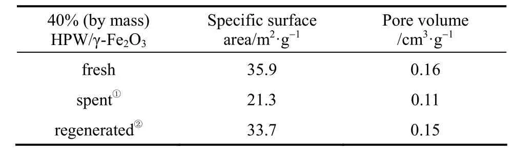
① After the 6th run.② Calcinated at 350 °C for 4 h.
4 CONCLUSIONS
A set of superparamagnetic catalyst with different loading of HPW/γ-Fe2O3have been successfully prepared through incipient wet impregnation method. Characterization investigation have shown that the Keggin structure of HPW keeps intact on the support and 40% (by mass) HPW/γ-Fe2O3supported catalyst displays almost the same thermal durability as the bulk HPW. Also, it is mesoporous material with specific surface area of 35.9 m2·g−1and pore volume of 0.16 cm3·g−1. In addition, the 40% (by mass) loading catalyst keeps the characteristics of superparamagnetismwith the magnetization of 26.1 A·m2·kg−1and can be easily separated magnetically.
The superparamagnetic solid catalysts have been tested for FCC gasoline desulfurization by model reaction of alkylation of thiophene with 1-octene. The catalysts show high catalytic activity and the conversation of thiophene is up to 46% under the optimum conditions. Furthermore, the catalyst is reusable by calcinating at 350 °C for 4 h, and keeps its property of superparamagnetism.
REFERENCES
1 Bellière, V., Lorentz, C., Geantet, C., Yoshimura, Y., Laurenti, D., Vrinat, M., “Kinetics and mechanism of liquid-phase alkylation of 3-methylthiophene with 2-methyl-2-butene over a solid phosphoric acid”, Appl. Catal. B Environ., 64, 254-261 (2006).
2 Takatsuka, T., Inoue, S., Wada, Y., “Deep hydrodesulfurization process for diesel oil”, Catal. Today, 39, 69-75 (1997).
3 Jaimes, L., Badillo, M., de Lasa, H., “FCC gasoline desulfurization using a ZSM-5 catalyst interactive effects of sulfur containing species and gasoline components”, Fuel, 90, 2016-2025 (2011).
4 Martínez-Magadán, J.M., Oviedo-Roa, R., García, P., Martínez-Palou, R.,“DFT study of the interaction between ethanethiol and Fe-containing ionic liquids for desulfuration of natural gasoline”, Fuel Process. Technol., 97, 24-29 (2012).
5 Huff, G.A., Owen, O.S., Alexander, B.D., Rundell, D.N., Reagan, W.J., Yoo, J.S., “Sulfur removal by catalytic distillation”, US Pat., 5863419 (1999).
6 Brunet, S., Mey, D., Perot, G., Bouchy, C., Diehl, F., “On the hydrodesulfurization of FCC gasoline: A review”, Appl. Catal. A Gen., 278, 143-150 (2005).
7 Zhang, Z.K., Jiang, H., Liu, S.L., Wang, Q.X., Xu, L.Y., “Alkylation performance of thiophene and derivatives during olefinic alkylation of thiophenic sulfur in gasoline”, Chin. J. Catal., 27, 309-313 (2006).
8 Bellière, V., Geantet, C., Vrinat, M., Ben-Taârit, Y., Yoshimura, Y.,“Alkylation of 3-methylthiophene with 2-methyl-2-butene over a zeolitic catalyst”, Energy Fuels, 18, 1806-1813 (2004).
9 Hu, L., Zhang, Z., Xie, S., Liu,S., Xu,L., “Effect of grain size of zeolite Y on its catalytic performance in olefin alkylation thiophenic sulfur process”, Catal. Commun., 10, 900-904 (2009).
10 Zhang, Z.K., Niu, X.L., Liu, S.L., Zhu, X.X., Yu, H.W., Xu, L.Y.,“The performance of HMCM-22 zeolite catalyst on the olefin alkylation thiophenic sulfur in gasoline”, Catal. Commun., 9, 60-64 (2008).
11 Zhang, Z.K., Liu, S.L., Zhu, X.X., Wang, Q., Xu, L.Y., “Modification of Hb zeolite by fluorine and its influence on olefin alkylation thiophenic sulfur in gasoline”, Fuel Process. Technol., 89, 103-109 (2008).
12 Shi, R.G., Li, Y.H., Wang, R., Guo, B.S., “Alkylation of thiophenic compounds with olefine and its kinetics over MCM-41 supported phosphoric acid in FCC gasoline”, Catal. Lett., 139, 114-122 (2010).
13 Guo, B.S., Wang, R., Li, Y.H., “The performance of solid phosphoric acid catalysts and macroporous sulfonic resins on gasoline alkylation desulfurization”, Fuel Process. Technol., 91, 1731-1735 (2010).
14 Arias, M., Laurenti, D., Bellière, V., Geantet, C., Vrinat, M., Yoshimura, Y., “Preparation of supported H3PW12O40·6H2O for thiophenic compounds alkylation in FCC gasoline” Appl. Catal. A Gen., 348, 142-147 (2008).
15 Arias, M., Laurenti, D., Bellière, V., Geantet, C., Vrinat, M., Yoshimura, Y., “Gasoline desulfurization by catalytic alkylation over silicasupported heteropolyacids: From model reaction to real feed conversion”, Catal. Today, 130, 190-194 (2008).
16 Guo, B.S., Wang, R., Li, Y.H., “Gasoline alkylation desulfurization over Amberlyst 35 resin: Influence of methanol and apparent reaction kinetics”, Fuel, 90, 713-718 (2011).
17 Kozhevnikov, I.V., “Sustainable heterogeneous acid catalysis by heteropoly acids”, J. Mol. Catal. A: Chem., 262, 86-92 (2007).
18 Kamiya, Y., Ooka, Y., Obara, C., Ohnishi, R., Fujita, T., Kurata, Y., Tsuji, K., Nakajyo, T., Okuhara, T., “Alkylation-acylation of p-xylene with butyrolactone or vinylacetic acid catalyzed by heteropolyacid supported on silica”, J. Mol. Catal. A Chem., 262, 77-85 (2007).
19 Angelis, A., Amarilli, S., Berti, D., Montanari, L., Perego, C., “Alkylation of benzene catalysed by supported heteropolyacids”, J. Mol. Catal. A Chem., 146, 37-44 (1999).
20 Yadav, G..D., Bokade, V.V., “Novelties of heteropoly acid supported on clay: Etherification of phenethyl alcohol with alkanols”, Appl. Catal. A Gen., 147, 299-323 (1996).
21 Nandhini, K.U., Arabindoo, B., Palanichamy, M., Murugesan, V.,“t-Butylation of phenol over mesoporous aluminophosphate and heteropolyacid supported aluminophosphate molecular sieves”, J. Mol. Catal. A Chem., 223, 201-210 (2004).
22 Guo, P.M., Huang, F.H., Huang, Q.D., Zheng, C., “Biodiesel production using magnetically stabilized fluidized bed reactor”, Renew. Energy, 38, 10-15 (2012).
23 Lei, Z.G., Li, C.Y., Li, J.W., Chen, B.H., “Suspension catalytic distillation of simultaneous alkylation and transalkylation for producing cumene”, Sep. Purif. Technol., 34, 265-271 (2004).
24 Webb, C., Kang, H.K., Moffat, G., Williams, R.A., Estévez, A.M., Cuéllar, J., Jaraiz, E., Galán, M.A., “The magnetically stabilized fluidized bed bioreactor: A tool for improved mass transfer in immobilized enzyme systems?”, Chem. Eng. J., 61, 241-246 (1996).
25 Li, W., Zong, B.N., X.F., Meng, X.K., Zhang, J.L., “Interphase mass transfer in G-L-S magnetically stabilized bed with amorphous alloy SRNA-4 catalyst”, Chin. J. Chem. Eng., 14, 734-739 (2006).
26 Zhang, D.L., Zhang, Y.J., Zhang, J.L., Li,X.F., Lu, L.X., Meng, X.K., Mu,X.H., “Axial liquid dispersion characteristics in magnetically stabilized bed,” Chin. J. Chem. Eng., 14, 532 -536 (2006).
27 Satish Kumar, G., Vishnuvarthan, M., Palanichamy, M., Murugesan, V., “SBA-15 supported HPW: Effective catalytic performance in the alkylation of phenol”, J. Mol. Catal. A Chem., 260, 49-55 (2006).
28 Wang, J.Y., Wang, X.Q., Li, R., Wang, Q., Li, L., Liu, W.M., Wan, Z.F., Yang, L.Y., Sun, P., Ren, L.L., Li, M.L., Wu, H., Wang, J.F., Zhang, L., “Conjugation of biomolecules with magnetic protein microspheres for the assay of early biomarkers associated with acute myocardial infarction”, Anal. Chem., 81, 6210-6217 (2009).
29 Izumi, Y., Ogawa, M., Urabe, K., “Alkali metal salts and ammonium salts of Keggin-type heteropolyacids as solid acid catalysts for liquid-phase Friedel-Crafts reactions”, Appl. Catal. A Gen., 132, 127-140 (1995).
30 Zhang, J.X., Sun, W., Bergman, L., Rosenholm, J. M., Lindén, M., Wu, G.J., Xu, H., Gu, H.C., “Magnetic mesoporous silica nanospheres as DNA/drug carrier”, Mater. Lett., 67, 379-382 (2012).
31 Kroll, E., Winnik, F.M., “In situ preparation of nanocrystalline γ-Fe2O3in iron(II) cross-linked alginate gels”, Chem. Mater., 8, 1594-1596 (1996).
32 Schmidt, L.D., The Engineering of Chemical Reactions, Oxford University Press, Oxford, 362-378 (2005).
33 Leng, Y., Wang, J., Zhu, D.R., Wu, Y.J., Zhao, P.P., “Sulfonated organic heteropolyacid salts: Recyclable green solid catalysts for esterifications”, J. Mol. Catal. A Chem., 313, 1-6 (2009).
34 Soled, S., Miseo, S., McVicker, G., Gates, W.E., Gutierrez, A., Paes, J., “Preparation and catalytic properties of supported heteropolyacid salts”, Chem. Eng. J., 64, 247-254 (1996).
1 INTRODUCTION
ine desulfurization has
increasing attention in recent decades primarily for environmental reasons. The increasingly strict regulations against sulfur contents in the fluid catalytic cracking (FCC) gasoline require the development of new refining techniques [1]. Accounting for 85%-95% of the amount of sulfur emission, such as SOχ, from fuel oil, FCC gasoline is by far the largest contributor to the pollution of sulfur emission. To solve this problem, one of the possible approaches is hydrodesulfurization (HDS) [2]. However, hydrogenation consumes high-energy, reduces octane number and decreases the gasoline quality [3, 4]. Recently, new non-HDS technologies for production of low-sulfur clean fuels were investigated in order to remove organic sulfur from different petroleum fractions, including the process of the olefinic alkylation of thiophenic sulfur (OATS) invented by British Petroleum in 1999, which is a quite attractive way to deal with the problem without decreasing octane number and wasting large amount of energy [5]. This technique utilizes acidic catalysis for alkylation of thiophene and its derivatives with the olefine being present in the gasoline to change the boiling point of thiophene and its derivatives. By doing this, the heavier thiophenic derivatives can be removed from gasoline by distillation to attain the goal of desulfurization [6, 7].
CATALYSIS, KINETICS AND REACTION ENGINEERING
Chinese Journal of Chemical Engineering, 22(3) 305—311 (2014)
10.1016/S1004-9541(14)60053-7
Received 2012-10-11, accepted 2013-04-30.
*Supported by the National Natural Science Foundation of China (21076047).
**To whom correspondence should be addressed. E-mail: gzdxlzl@gmail.com
猜你喜欢
杂志排行

Chinese Journal of Chemical Engineering的其它文章
- Determination of Transport Properties of Dilute Binary Mixtures Containing Carbon Dioxide through Isotropic Pair Potential Energies
- Preparation and Characterization of Sodium Sulfate/Silica Composite as a Shape-stabilized Phase Change Material by Sol-gel Method*
- A Bi-component Cu Catalyst for the Direct Synthesis of Methylchlorosilane from Silicon and Methyl Chloride
- A Contraction-expansion Helical Mixer in the Laminar Regime*
- Effects of Shape and Quantity of Helical Baffle on the Shell-side Heat Transfer and Flow Performance of Heat Exchangers*
- Hydrodynamics and Mass Transfer of Oily Micro-emulsions in An External Loop Airlift Reactor