Experiment on Adiabatic Film Cooling Effectiveness in Front Zone of Effusion Cooling Configuration*
2014-05-05YangZhimin杨志民ZhangJingzhou张靖周
Yang Zhimin(杨志民),Zhang Jingzhou(张靖周)
1.School of Energy and Power Engineering,Beihang University,Beijing,100191,P.R.China;2.Shenyang Engine Design and Research Institute,Aviation Industry Corporation of China,Shenyang,110015,P.R.China;3.Jiangsu Province Key Laboratory of Aerospace Power System,Nanjing University of Aeronautics and Astronautics,Nanjing,210016,P.R.China;4.Collaborative Innovation Center of Advanced Aero-engine,Beijing,100191,P.R.China
1 Introduction
As a matter of fact,the inlet and exit temperature levels are progressively getting higher in modern gas-turbine combustors while the percentage of compressed air available for cooling purpose becomes more limited.Undoubtedly,the decrease of the quantity of cooling air available and the increase of the gas temperature in the combustor are contradictory elements of the problem,which presents a great challenge for engineers to design an efficient cost-effective cooling system to meet combustor durability requirement.
In order to improve the reliability of the combustor liner exposed to hot gas,two technical routes are obligatory for satisfying this requirement.One is to improve the combustor liner material characteristics,and the other is to develop advanced combustor liner cooling configuration.As far as the latter is concerned,effusion cooling or fully coverage film cooling has shown advantage to protect and increase the lifetime of combustor liner for contributing high cooling effectiveness,aswell as uniform temperature distribution[1-4].
A lot of investigations on the mechanism of enhanced cooling of an effusion cooling scheme have been performed by many researchers.In reality,an effusion cooling scheme consists of three cooling effects:(1)the reduction of the wall temperature for an adiabatic wall as a direct result of the coolant jets;(2)the conduction of heat through the wall due to the thermal conductivity of the wallmaterial and the heat transfer to the backside flow;(3)the heat trans-fer to the coolant flow from the inner surface of the injection holes when coolant passes through the holes.The relative importance of each effect depends critically on the geometrical features of the wall and the operating conditions of the cooling system.
Although many studies have been conducted to investigate the effects of main geometric and aerothermal factors on the thermal and aerodynamic performances of effusion cooling scheme[5-16],such as the arrangement of effusion holes,hole shape,hole diameter and hole inclination angle,and blowing ratio,etc.,there is few concentration on the cooling characteristics in the front zone of effusion configuration.Previous works have shown that the forming of“continuous”or“developed”coverage film layer comes through a developing process of the coolant jets injected from the front rows of film holes[17-19].The effusion cooling feature in the developing zone is significantly different from that in the developed zone.Themotivation of the presented experimental study is to explore the cooling characteristics in the front zone of effusion configuration.Effects of blowing ratio,multi-holes arrangementmode,hole-to-hole pitch and jet orientation angle on the adiabatic film cooling effectiveness are concentrated on.
2 Experimental Procedures
2.1 Experimental setup

Fig.1 Schematic diagram of experimental setup
The experimental setup is sketched in Fig.1.The primary stream comes from compressed air supply(0.8 MPa)and passes through a calibrated orifice flow meter,after being heated by a 60 kW heater,which can heat the air to a free-stream temperature of 80 °C.The heated stream is then routed through a section with baffles to ensure adequate mixing of the hot air to obtain a uniform temperature at the crosssection of 150 mm width and 60 mm height.This cross-section makes the primary stream flow at25 m/s.The primary stream temperature is continuously monitored at the inlet of the test section by a thermocouple.The secondary stream or coolant air is provided from a separate compressed air supply and routed through a buoyage flow meter,which is controlled by a gate valve and introduced into the plenum cavity.To eliminate the impingement effect of the coolant air at the plenum inlet,multiple layers of grids are placed in the plenum cavity.The coolant stream is then ejected through the effusion cooling holes into the primary flow passage.The test section ismade of transparent plastic plate with thickness of 5 mm.The length of the test section is300 mm.An infrared viewing window,which is 80 mm wide and 120 mm long,ismounted on the test section for directly viewing themeasured surface by an infrared camera.
2.2 Experimentalmodels
The experimental model for an effusion cooling configuration is shown in Fig.2(a).The effusion plate ismade of epoxy resin with thickness of 3 mm.The holes inside the perforated plate are arranged in the staggered mode or the inline mode,as shown in Figs.2(b,c).In the present study,the effusion holes have the same diameter(d=2 mm).The streamwise pitch ratio(S/d)and spanwise pitch ratio(P/d)are varied from 3 to 5.The inclined angle(α)is setas35°and 90°,respectively.The effusion plate has length of 120 mm and width of 150 mm,which ismounted inside the test section.
The geometries of the effusion plates are summarized in Table 1.
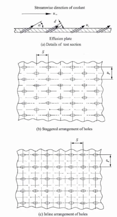
Fig.2 Schematic diagram of effusion cooling scheme
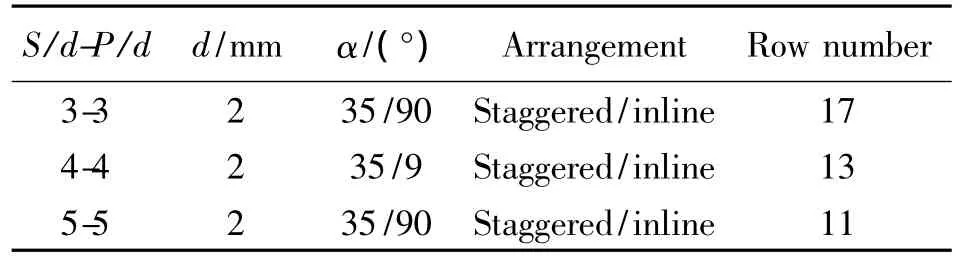
Table 1 Effusion plate geometries
2.3 M easurement and parameter definition
To study the effect of various amount of coolant flow on the film cooling for a fixed mainstream flow,a parameter known as the blowing ratio(M)is defined as
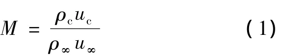
whereρcand ucare the density and velocity of the secondary flow or coolant flow at the effusion hole exit,respectively;and ρ∞and u∞are the density and velocity of the primary flow,respectively.
The adiabatic wall cooling effectiveness(ηad)is defined as
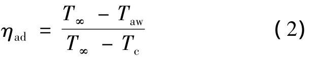
where Tcis the coolant flow temperature,T∞the primary flow temperature,T∞the primary flow temperature,Tawthe adiabatic wall temperature at the effusion surface suffering the primary flow.Since the thermal conductivity of effusion plate is about 0.4 W/(m·K),the heat transfer on the backside surface and inside effusion holes of the effusion plate is very weak.Therefore,the temperature on the effusion surface may be regarded approximately as the adiabatic temperature.
The temperature distributions on the face of the effusion plate aremeasured by an infrared camera operating in themiddle infrared band(8~14 m)of the infrared spectrum.The test surface is viewed through the infrared camera window(Fig.1).The infrared camera calibration is conducted using a series of thermocouples placed on the black painted test surface to act as the benchmark[20-22].These thermocouples are used to estimate the emissivity of the test surface.The emissivity of the black painted test when viewed without thewindow is about0.96.The calibrated transmissivity for the infrared camera window is about0.85.
To eliminate the effect of the edge area on the data treatment,the laterally-averaged adiabatic cooling effectiveness is determined on the centric zone of effusion plate.
Experimental uncertainty in the overall film effectiveness measurement is estimated to be about ± 8.4%using the methodology of Moffat[23].The individual uncertainties of primary mainstream temperature(T∞),coolant temperature(Tc),and surface temperature(Taw)are ±1 °C,±0.5 °C,±2.0 °C,respectively.
3 Results and Discussion
Fig.3 presents the laterally-averaged adiabatic cooling effectiveness distributions along the streamwise direction at different blowing ratios.Here the original coordinate is located at the centre of the first row film holes.
For either the staggered mode or inline mode,the film flow displays an obvious“developing”feature in the front zone of effusion cooling configuration.The film outflows injected from the front rows do notmerge together to form a uniform film layer,therefore the laterally-averaged adiabatic cooling effectiveness increases or the adiabatic temperature decreases rapidly along the streamwise direction.By comparison,the varying gradient of the laterally-averaged adiabatic cooling effectiveness along the streamwise direction is greater in the staggered mode than that in the inline mode.Thismeans that the staggered mode will benefit the development of film flow and is capable of achieving full film coverage by fewer number of effusion cooling-holes rows.
For the staggered arrangement,the laterally-averaged adiabatic film cooling effectiveness originated from the first few rows is higher under the lower blowing ratio,which agrees well with the results of discrete film cooling from early studies[24,25].Under a lower blowing ratio,the coolant jet has the lower penetration capacity,which is helpful tomake the coolant jet covering the downstream surface of the holes.But formulti-rows of film cooling holes,themaintainance capacity of jet spreading along streamwise direction under lower blowing ratio is also lower,thus leading to a slower growth of film layer.Also,the vigorous film layer is provided with the ability of suppressing coolant jet penetration.Therefore,the laterally-averaged adiabatic film cooling effectiveness originated from the last few rows is higher under a bigger blowing ratio.
For the inline arrangement,the film coverage in the lateral direction is seriously weaker than that of the staggered mode.The inlinemode thus needs longer developing stage to realize the full film coverage.The laterally-averaged adiabatic film cooling effectiveness in the front zone of effusion cooling configuration decreases with the increase of blowing ratio.
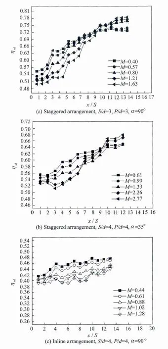
Fig.3 Laterally-averaged adiabatic cooling effectiveness distributions at different blowing ratios
Fig.4 presents the laterally-averaged adiabatic cooling effectiveness distributions along the streamwise direction under different multi-hole arrangements.As discussed in the above,the varying gradient of the laterally-averaged adiabatic cooling effectiveness along the streamwise direction is obviously lower for the inline arrangement than that for the corresponding staggered arrangement.The laterally-aver-aged adiabatic cooling effectiveness for the staggered mode is also higher than that for the corresponding value of inlinemode at the same blowing ratio.
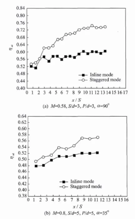
Fig.4 Laterally-averaged adiabatic cooling effectiveness distributions under different hole arrangements
Fig.5 shows the laterally-averaged adiabatic cooling effectiveness distributions along the streamwise direction under different jet orientation angles.Either for the staggered mode or the inlinemode,the laterally-averaged adiabatic cooling effectiveness with jet orientation angle of 35°is greater than that of 90°angle.As the coolant is discharged with a certain inclined angle,the coolant flow velocity components from effusion holes can be divided into two parts,i.e.,the tangent velocity and the normal velocity.In the tangential direction,the coolant is forced to flow downstream the film hole,which is also called aswall jet.From the view of enhancing film cooling effectiveness,the greater tangent velocity is expected tomaintain wall jet momentum along the streamwise direction.While in the normal direction,it is the opposite case.The coolant flow penetrates the primary flow and lifts off the surface.As expected,the lower coolant jet penetration along normal direction and the higher spread along streamwise direction with the inclined discharge are to benefit the film cooling effectiveness.
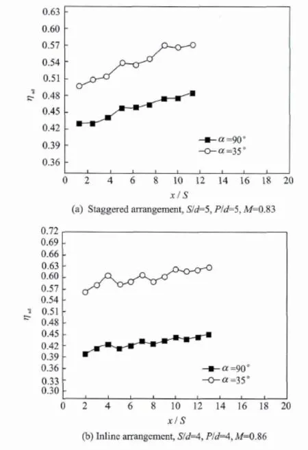
Fig.5 Laterally-averaged adiabatic cooling effectiveness distributions under different jet orientation angles
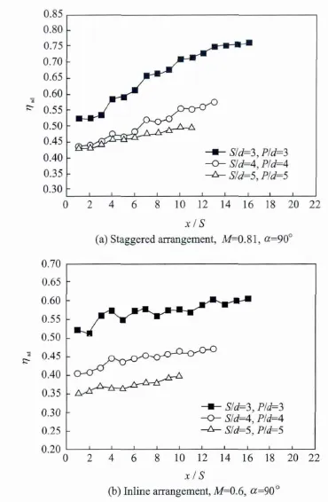
Fig.6 Laterally-averaged adiabatic cooling effectiveness distributions under different hole-to-hole pitches
Fig.6 presents the laterally-averaged adiabatic cooling effectiveness distributions along the streamwise direction under different hole-to-hole pitches.According to the work of Yang and Zhang[19]on the cooling film development of staggered arrangement,the development of film layer of the effusion cooling scheme could be divided into three stages.Firstly,the film cooling effectiveness increases rapidly along streamwise direction in the front rows of multi-holes where the film layer is undergoing a developing stage.Then the laterally averaged adiabatic film cooling effectiveness increases tardily in the middle rows of multi-hole where the film layer is undergoing a transition stage.Finally,once the effusion film layer is developed,the laterally averaged adiabatic film cooling effectiveness should trend to be constant.Generally,the transition stage is accomplished in the 17th row.For the small pitches(such as S/d=P/d=3),this feature iswell demonstrated.While for the large pitches,film layer is undergoing the developing stage.The holes array arranged with small pitches is in favor of obtaining a developed film layer.
According to the varying trend of the laterally-averaged adiabatic film cooling effectiveness along streamwise direction for the inline arrangement,it is deduced that the film layer developmentwill be very slower than that for the staggered arrangement.The reason has been discussed in the above.
4 Conclusions
(1)The varying gradientof the laterally-averaged adiabatic cooling effectiveness along the streamwise direction in the front zone of effusion cooling configuration is greater for the staggered mode than that of the inline mode.The laterally-averaged adiabatic cooling effectiveness for the staggered mode is higher than the corresponding value of inline mode at the same blowing ratio.(2)For the staggered multi-holes mode,the laterally-averaged adiabatic film cooling effectiveness originated from the first few rows is higher under the lower blowing ratio.While for the last few rows,the higher film cooling effectiveness is achieved under a bigger blowing ratio.The holes array arranged with small hole-to-hole pitches is in favor of obtaining developed film coverage layer rapidly.(3)Either for the staggered arrangement or the inline arrangement,the laterally-averaged adiabatic cooling effectiveness with inclined jet orientation angle of 35°is greater than the corresponding value of normal orientation angle at the same blowing ratio.The lower coolant jet penetration along the normal direction and higher spread along the streamwise direction with the inclined discharge is benefit to the film cooling effectiveness.
[1] Leger B,Miron P,Emidio JM.Geometric and aerothermal influences onmultiholed plate temperature:application on combustor wall[J].International Journal of Heat and Mass Transfer,2003,46:1215-1222.
[2] Jeromin A,Eichler C,Noll B,et al.Full 3D conjugate heat transfer simulation and heat transfer coefficient prediction for the effusion-cooled wall of a gas turbine combustor[R].ASME GT2008-50422,2008.
[3] Andreini A,Bonini A,Caciolli G,et al.Numerical study of aerodynamic losses of effusion cooling holes in aero-engine combustor liners[J].ASME Journal of Engineering for Gas Turbines and Power,2011,133:021901-1-10.
[4] Krewinkel R.A review of gas turbine effusion cooling studies[J].International Journal of Heat and Mass Transfer,2013,66:706-722.
[5] Andrews G E,Khalifa IM,Asere A A,etal.Full coverage effusion film cooling with inclined holes[R].ASME Paper 95-GT-274,1995.
[6] Gustafsson K M,Johansson TG.An experimental study of surface temperature distribution on effusion-cooled plates[J].ASME Journal of Engineering for Gas Turbines and Power,2001,123:308-316.
[7] Harrington M K,McWaters M A,Bogard D G,et al.Full-coverage film cooling with short normal injection holes[J].Journal of Turbomachinery,2001,123:798-806.
[8] Lin Yuzhen,Song Bo,Li Bin,et al.Investigation of film cooling effectiveness of full-coverage inclined multihole walls with different hole arrangements[R].ASME GT2003-38881,2003.
[9] Scrittore JJ,Thole K A,Burd SW.Investigation of velocity profiles for effusion cooling of a combustor liner[J].ASME Journal of Turbomachinery,2007,129:518-526.
[10] Li Bin,Ji Honghu,Jiang Yijun,et al.Experimental and numerical analysis of temperature distribution on floating-wall flame tube of combustor[J].Journal of Nanjing University of Aeronautics and Astronautics,2007,39(6):771-774.(in Chinese)
[11] Zhang Jingzhou,Xie Hao,Yang Chengfeng.Numerical study on flow and heat transfer of impingement-effusion cooling[J].Chinese Journal of Aeronautics,2009,22(4):343-348.
[12] Zhang Chi,Song Bo,Lin Yuzhen,etal.Cooling effectiveness of effusion walls with deflection hole angles measured by infrared imaging[J].Applied Thermal Engineering,2009,29:966-972.
[13] Yang Chengfeng,Zhang Jingzhou,YangWeihua.Effect of the holes array arrangement on the full coverage film cooling characteristics[J].Journal of Aerospace Power,2010,25(7):1524-1529.(in Chinese)
[14] Yang Weihua,Peng Jianyong,Cao Jun,et al.Experimental study on cooling effectiveness of compound cooling configurations in reverse flow combustor[J].Journal of Nanjing University of Aeronautics and Astronautics,2012,44(6):769-774.(in Chinese)
[15] Xie Jie,Zhang Jingzhou.Numerical simulation on cooling characteristics of effusion wall with deflection film outflow[J].Journal of Nanjing University of Aeronautics and Astronautics,2013,45(2):157-161.(in Chinese)
[16] Yang Qian,Lin Yuzhen,Zhang Chi,et al.Cooling effectiveness comparison between effusion cooling and impingement/effusion cooling[J].Journal of Aerospace Power,2014,28(2):268-275.(in Chinese)
[17] Bohn D,Moritz N.Influence of hole shaping of staggered multi-hole configurations on cooling film development[R].AIAA Paper 2000-2579,2000.
[18] Petre B,Dorignac E,Vullierme J J.Study of the influence of the number of holes rows on the convective heat transfer in the case of full coverage film cooling[J].International Journal of Heat and Mass Transfer,2003,46:3477-3496.
[19] Yang Chengfeng,Zhang Jingzhou.Influence of multihole arrangement on cooling film development[J].Chinese Journal of Aeronautics,2012,25:182-188.
[20] Carlomagno G M,Cardone G.Infrared thermography for convective heat transfermeasurements[J].Experiments in Fluids,2010,49:1187-1218.
[21] Yang Chengfeng,Zhang Jingzhou.Experimental investigation on film cooling characteristics from a row of holes with ridge-shaped tabs[J].Experimental Thermal and Fluid Science,2012,37:113-120.
[22] Yu Yezheng,Zhang Jingzhou,Xu Huasheng.Convective heat transfer by a row of confined air jets from round holes equipped with triangular tabs[J].International Journal of Heat and Mass Transfer,2014,72:222-233.
[23] Moffat R J.Describing the uncertainties in experimental results[J].Experimental Thermal and Fluid Science,1988,1:3-17.
[24] Schmidt D L,Sen B,Bogard D G.Film cooling with compound angle holes:adiabatic effectiveness[J].ASME Journal of Turbomachinery,1996,118:807-813.
[25] Gritsch M,Schulz A,Wittig S.Adiabatic wall effectivenessmeasurements of film cooling holeswith expanded exits[J].ASME Journal of Turbomachinery,1998,120:549-556.
猜你喜欢
杂志排行

Transactions of Nanjing University of Aeronautics and Astronautics的其它文章
- Control System in M issiles for W hole-Trajectory-Controlled Trajectory Correction Projectile Based on DSP
- Panoram ic Imaging System Inspired by Insect Com pound Eyes*
- Analysis for Transm ission of Com posite Structure w ith Graphene Using Equivalent Circuit M odel*
- Geometric Covariance Modeling for Surface Variation of Compliant Parts Based on Hybrid Polynomial Approximation and Spectrum Analysis*
- Focus Reflective Shock Wave Interaction with Flame
- Fast SSED-MoM/FEM Analysis for Electromagnetic Scattering of Large-Scale Periodic Dielectric Structures*