Fatigue Life Prediction under Service Load Considering Strengthening Effect of Loads below Fatigue Limit
2014-02-07ZHAOLihuiZHENGSonglinandFENGJinzhi
ZHAO Lihui ,ZHENG Songlin *,and FENG Jinzhi
1 College of Mechanical Engineering,University of Shanghai for Science and Technology,Shanghai 200093,China
2 College of Automobile Engineering,Shanghai University of Engineering Science,Shanghai 201620,China
3 Machinery Industry Key Laboratory for Mechanical Strength &Reliability Evaluation of Auto Chassis Components,University of Shanghai for Science and Technology,Shanghai 200093,China
1 Introduction*
Accurately predicting the fatigue life according to the service loading histories is essential to the lightweight and reliability design of mechanical products.Traditionally,this was achieved based on the number of load cycles counted from loading history and load-life relations(S-N curve)from constant amplitude load(CAL)tests by the Palmgren-Miner Rule(PMR)D=ni/Ni,and when D=1 failure occurs[1].Here D is the cumulative damage,niis the mumber of cycles of load with an amplitude Si,and Niis the fatigue life under this amplitude.However,numerous studies have shown that the cumulative damage D calculated from experimental tests under variable amplitude loads often deviate from 1.SCHUTZ[2]pointed that damage sum D typically ranges from 0.3 to 3,but can reach as much as 0.1 to 10.Studies carried out by WIRSCHING,et al[3]and LEE,et al[4]also found that D may range from 0.15 to 1.06 under different loadings.This means PMR would result in poor predictions,cumulative damage less than one will lead to unsafe(non-conservative)prediction,while larger than one to conservative results[5].
With regard to the situation that D<1,it is believed that the fatigue damage of load cycles below the fatigue limit were ignored,which was induced by the reduction of fatigue strength caused by previous amplitudes above the fatigue limit[6].So,many alternatives were proposed to cover this deficiency.Three major alternatives are:(i)modified miner’s rule(MMR),which extends the S-N curve to lower amplitudes with a slope k′=k or k′=2k-11[7];(ii)relative miner rule(RMR),which replaces the damage sum till failure D=1 with a relative smaller value D=q(q<1)[8];(iii)combination of MMR and RMR,which both extends the S-N curve and replaces the damage value,such as the design recommendation of welding structures from International Institute of Welding(IIW)[9].STANZEL,et al[10],tested AISI C1020 steel under random loadings and good agreement was found for measured and calculated results according to MMR.SCHUTZ[8]studied the results reported in literature and suggested that a damage value ranging from 0.4 to 0.7 will lead to accurate predictions for RMR.SONSINO,et al[11],conducted fatigue tests of four industrial sectors and found experimental results were all comparable to IIW Recommendations.
Although the application of these methods effectively improved the accuracy of fatigue life prediction of this situation,they were not suitable for the situation that D>1,under which predicted lives were conservative compared with test lives.LIN,et al[12],calculated the fatigue life of motorcycle handlebar under service loadings using PMR and results show that the ratio of predicted life to test life was between 0.37 and 0.66.FRICKE,et al[13],studied the accuracy of three stress approaches for the fatigue assessment of welded structures,and pointed that predicted lives were shorter than test life except for one occasion.XU,et al[14],predicted the fatigue life of an automotive rear axle,and found that the ratio of life prediction to experiment was 0.42,0.45 and 0.59 for different location.Under these situations,the aforementioned alternatives would result in more conservative predictions.Due to a conservative prediction would lead to the safe side of a design;it did not attractive enough consideration for a long time.But with the lightweight design becomes more of a concern,it is necessary to improve the accuracy of fatigue life prediction,because too conservative a predicted life will lead to a heavy structure design because of a higher safe factor.
The situation that D>1 was caused by an excessive calculation of damage of load cycles[6].This is because the aforementioned methods were established on the baiss that load cycles,no matter above or below the fatigue limit,are damaging.Actually,not all of the load cycles were damaging.Many studies show that the fatigue strength of the materials with strain aging could be improved by gradually increasing the applied load from a level below the fatigue limit[15–16].KAWAMOTO,et al[17]and IKAI,et al[18],investigated the strengthening effect of pre-stressing on fatigue strength using low carbon steel,and concluded that the fatigue strength was increased and gradually saturated with the increase of number of load cycles.WANG,et al[19],studied the influence of different load amplitudes on fatigue damage by means of comparative fatigue tests,and found that fatigue life will reach valley point when omitting the amplitudes around 20% of the biggest load in load spectrum.Refs.[20–22]study the strengthening effects of loads using three carbon steels with different ultimate tensile strength(UTS).The results show that the load amplitudes with strengthening effect are between 65% and 95% of the fatigue limit(low-amplitude-load strengthening,LALS),and the fatigue strength and fatigue life of the research objects are increased obviously,by 3%–22% and 80%–130%,separately.An increase in fatigue life will lead to a decrease of calculated damage,thus the accuracy of fatigue life prediction could be effectively improved using this concept.
The purpose of this study is to propose a practical method for fatigue life prediction under service loading histories by taking into account the strengthening effect of load cycles below the fatigue limit.First,the phenomenon and mechanism of LALS were briefly reviewed.Then the mechanics model was derived and the method was established.Finally,validations were made using two examples,half shaft and torsion beam rear axle of automobile.Also fatigue lives are predicted with MMR(k′=k and k′=2k-1)for a further comparison.
2 Fatigue Life Prediction Based on LALS
2.1 Brief review of LALS
Refs.[20–22]study LALS by fatigue tests of three vehicle components made of carbon steel,which are front axle(No.20 steel),half shaft(40Cr)and spur gear(20MnCr5).In the experiments,specimens were divided into two groups.For one group,fatigue test of each specimen was conducted under a load cycle above the fatigue limit(proving load,Ld),and fatigue life N0was obtained.For the other group,each specimen was first loaded by a load below the fatigue limit(strengthening load,Ls)for a certain number of cycles(strengthening number,ns),then fatigue test was conducted under the same proving load and the new fatigue life Nswas obtained.Results showed that the fatigue performances of all the three components could be significantly improved.The fatigue life under proving load after strengthened varies with Lsand ns,and can reach as much as 1.81,2.30,2.09 times of the original life for front axle,half shaft and spur gear.The relationship of strengthened life Nfvs.strengthening load Lsand strengthening number of cycles nswas shown in Fig.1.
Using scanning electron microscopy(SEM),transmission electron microscopy(TEM),Zheng studied the microscopic mechanisms of LALS and conclusions were summarized as follows[23].
i)Results from SEM show that the pores in the material became smaller,and secondary cracks were lesser and thinner after strengthened,see in Fig.2(a)and Fig.2(b)[23].This means the material become more uniform and compact,postponing the fatigue crack initiation and propagation,and thus resulting in an increased fatigue strength and fatigue life.
ii)TEM results indicate that after strengthened by loads below the fatigue limit,dislocations within grains gradually moved to the grain boundaries.The accumulation of dislocation along grain boundaries forms a dislocation wall which restricts further movement of dislocations.The strong strain energy gathered in the wall increases the friction among lattices and raises the local yield stress,and finally leading to an improvement in fatigue strength and fatigue life.
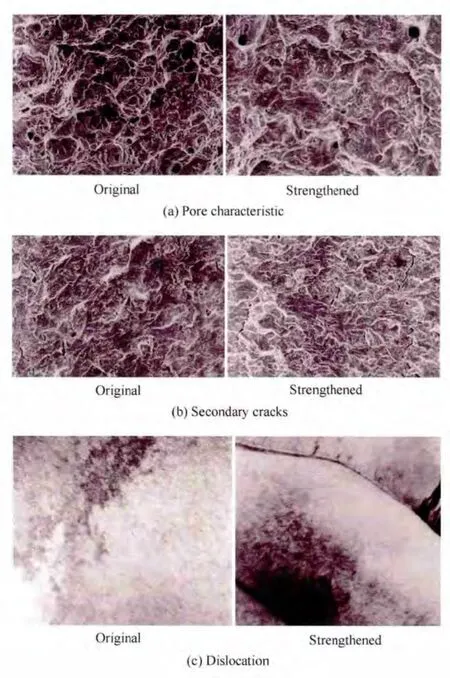
Fig.2.Microscopic mechanism of LALS
2.2 Mechanics model of LALS
The increase of fatigue life means an improvement in fatigue strength.However,the results can only verify that the fatigue strength was improved under a certain load level.It's necessary to know the strengthening effect under different load levels for the application of fatigue life prediction.According to Basquin relation[1],the S-N curve for high cycle fatigue(HCF)could be represented as

where S—Stress amplitude,
m—Inverse slope of S-N curve,
N—Fatigue life,
C—Fatigue constant.
If use σ–1to present the fatigue limit,and subscript 0 and 1 to identify the original and new S-N curve after strengthened by a load below fatigue limit,the strengthening effect can be regard as fatigue strength at life N1and Ncwere increased from S0to S1and from σ–1,0to σ–1,1separately,or the fatigue life at load level S1was increased from N0to N1,as shown in Fig.3.
From Fig.3 and Eq.(1),the following results can be obtained:

i.e.,

From Eq.(4),it can be easily seen that the previous S-N curve AC was parallel to the new one DE,which means the improvement of fatigue strength at different load levels are equal.So the new S-N curve,and eventually the new life can be easily calculated if knowing either of the two parameters S1or σ–1,1combining Eqs.(3)and(4).
Taking the percentage increment of fatigue strength ΔS%to represent the strengthening effect,the new fatigue life after strengthened could be easily derived from Eq.(4),and can be expressed as

2.3 Fatigue life prediction
Fig.1 shows that the fatigue life under proving load will first increase then decrease with the strengthening number of cycles,and there is a best strengthening number(Nb),at which the strengthening effect reaches the maximum.This indicates the strengthening effect of loads below fatigue limit accumulates with the strengthening number nsbefore it reaches Nb,then gradually decreases to zero when nsreaches a certain value.This could be interpreted as that the loads below fatigue limit are of strengthening effect when ns<Nb,and of damaging effect when ns>Nb.
Therefore,the process for fatigue assessment considering LALS under service loading history could be divided into two stages by the best strengthening number(Nb):stage I and stage II.During stage I,small load cycles are of strengthening effect and damage is calculated by the load cycles above the fatigue limit using a new fatigue life.In stage II,damage is calculated from both the loads above the fatigue limit and those with strengthening effect.While those smaller than strengthening loads can be ignored because they are of no effect on the fatigue strength.Combining with Miner’s Rule[1],the method for fatigue assessment of components under VAL taking into account LALS could be expressed as follows:
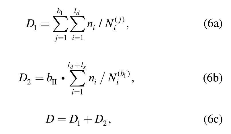
where D1—Damage value in stage I,
D2—Damage value in stage II,
bI—Number of repetitions of load block in stage I,
bII—Number of repetitions of load block in stage II,
ld—Number of load levels with damaging effect,
ls—Number of load levels with strengthening effect,
ni—Number of cycles of the ith load level,
Ni(j)—Fatigue life under the ith load level after strengthened by the previous j-1 load blocks.
When D=1,failure occurs.The total life in the form of repetitions of loading block is:Nblock=bI+bII.

Therefore,the procedure for fatigue life calculation under service loading blocks based on LALS could be performed as follows:
i)Count the number of cycles niof each load level Siin the load history,and determine the number of levels of strengthening load lsand damaging load ld;
ii)Calculate the number of repetitions of loading block bIto finish stage I based on lsand Nb,and calculate the fatigue life at the jth loading blockaccording to the original S-N curve and Eq.(7);
iii)Calculate the fatigue damage during stage I D1according to Eq.(6a),and the remaining damage during stage II with D2=1-D1according to Eq.(6c);
iv)Calculate the number of repetitions of loading block in Stage II using both the damaging and strengthening load levels according to Eq.(6b)by
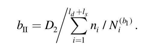
v)Calculate the total life in the form of loading block:Nblock=bI+bII.
3 Validations
Two examples,half shaft and rear axle,are used to validate the proposed method for the fatigue life prediction under service loading.For a further comparison,the fatigue lives of the two examples are also predicted with PMR and MMR.
3.1 Half shaft
The half shaft(Fig.4)was made of 40Cr.The mechanical properties of the material were as follows:ultimate tensile strength 980 MPa,yield strength 785 MPa.Service loading histories of half shaft were recorded on proving ground,and nominal stresses were calculated.The load spectrum with a sequence length Ls=21 262 was obtained after rain-flow cycle counting[24],see in Fig.5.In order to simplify calculation,an eight level block load was developed for fatigue assessment based on the rule of equivalent damage[25].The load levels and corresponding cycles were listed in Table 1.

Fig.4.Half shaft of automobile
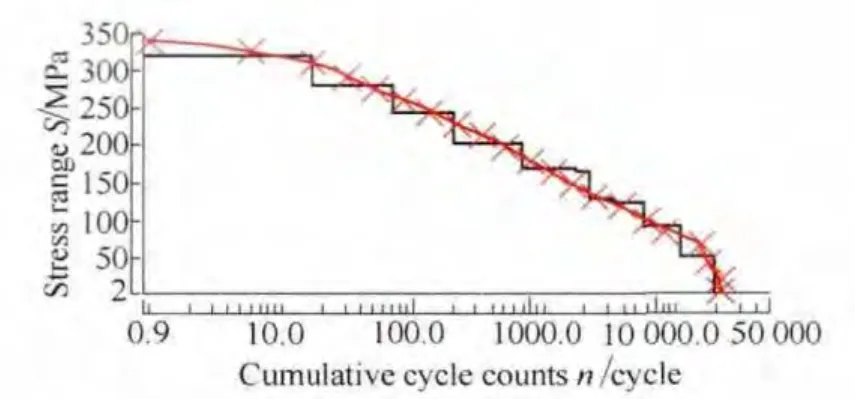
Fig.5.Load spectrum of half shaft
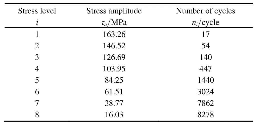
Table 1.Summary of block load of half shaft
The S-N curve with Ps=50% was determined by conducting torsional fatigue tests under constant amplitude loads at a stress ratio of R=-1,and could be expressed as

From Eq.(8),the fatigue limit τ–1(at N=2×10⁶)of half shaft was 100.87 MPa,therefore the loads with strengthening effect range from 65.57 to 95.83 MPa(0.65–0.95τ–1).So,load levels 1 to 4 were above fatigue limit;level 5(0.84τ–1)was of strengthening effect;levels 6 to 8 were out of strengthening region and can be neglected for fatigue life prediction.
For the mechanical characteristics of the material of half shaft were similar to that of transmission gear reported in Ref.[21],the strengthening effect of gear was taken for the fatigue life prediction of half shaft,of which the fatigue strength was increased by 4.2% after strengthened under a load at 0.84σ–1for 300 000 cycles.So the number of repetitions of load blocks to finish stage I was 208.Considering the strengthening effect to strengthening number as linear,the increment of fatigue strength of each load block was 0.020 2%,and the new fatigue life can be calculated according to Eq.(7).Then the fatigue life can be calculated according to Eq.(6):

So the total number of repetitions of loading block to failure is 1114.
Torsional fatigue tests of half shaft were conducted under random sequence of the eight-level block loading,Fig.6.Failure criterion was defined as the breakthrough of half shaft.Six specimens from the same batch were tested,and the fatigue lives were 1115,1289,930,1168,1395 and 1050 repetitions.The average value of experimental lives and predicted lives according to PMR,MMR and LALS are listed in Table 2.
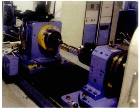
Fig.6.Test set-up of half shaft

Table 2.Comparisons of predicted and test lives of half shaft
3.2 Torsion beam rear axle
The torsion beam rear axle was made of TL1114 and comprised of eight components welded together.The mechanical properties of the material were as follows:ultimate tensile strength 500 MPa,yield strength 360 MPa.Fatigue failures occurred at the welding tip of torsion beam and reinforcing part,see in Fig.7.Service loading histories were recorded on proving ground using strain gauge and stress histories were calculated.Loading spectrum with a sequence length Ls=5951 was obtained after rain-flow counting,and an eight level loading block was derived for simplification of calculation,see in Fig.8.The block load levels and corresponding cycles were listed in Table 3.
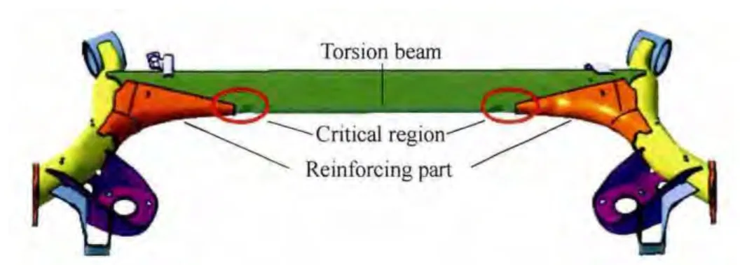
Fig.7.Torsion beam rear axle
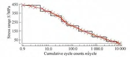
Fig.8.Load spectrum of rear axle
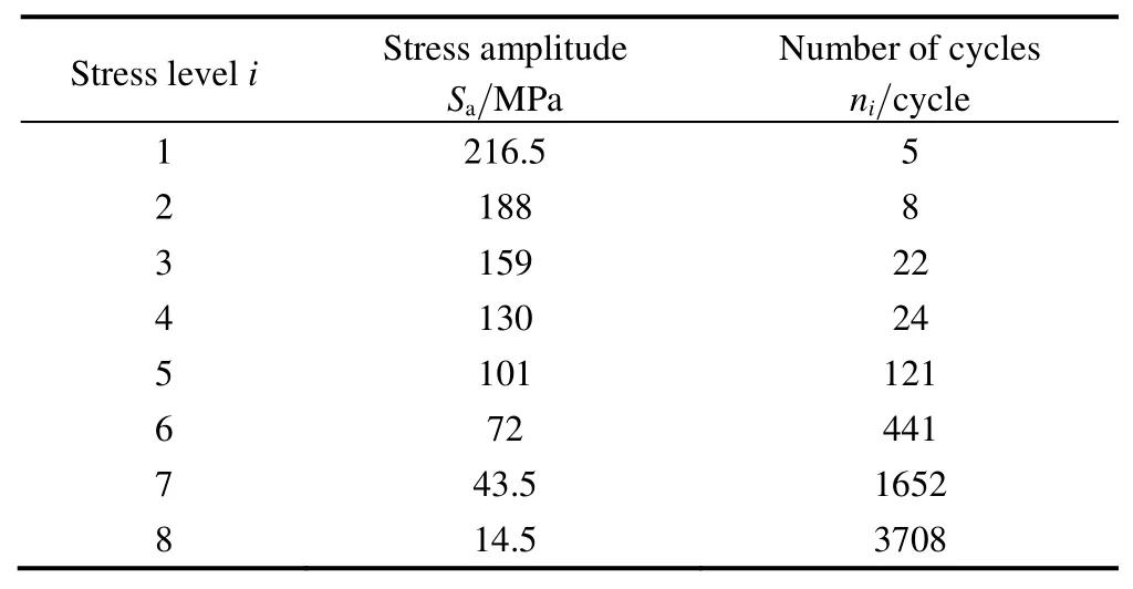
Table 3.Block loading of rear axle from service load on proving ground
The S-N curve with Ps=50% was determined by conducting fatigue tests under torsional loads with constant amplitude at a stress ratio of R=-1,and can be expressed as

From Eq.(9),the fatigue limit σ–1(at N=2×10⁶)was 82.48 MPa.Load with strengthening effect was between 53.62 and 78.36 MPa.So load level 1 to 5 were above fatigue limit;level 6(0.87σ–1)was of strengthening effect;level 7 to 8 can be omitted for fatigue life prediction.
Taking the strengthening effect of rear axle the same as front axle studied in Ref.[20],for they are of similar mechanical characteristics.According to the curve surface,the maximum increment of fatigue strength under a load at 0.87σ–1was 9.8%,and the best strengthening number Nbwas 200 000 cycles.So the number of repetitions of loading block to finish process I was 454,and the increase in fatigue strength of each block was 0.021 6%.Then the fatigue life prediction of rear axle under service loading history could be expressed as follows:
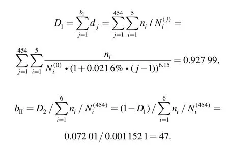
So the total number of repetitions of loading block was 501.
Fatigue tests were carried out on MTS 6DOF road load simulator,as shown in Fig.9.Six specimens from the same batch were tested,and the fatigue lives were 486,510,530,476,519 and 539 repetitions of loading block.The results of predicted and test lives were summarized in Table 4.
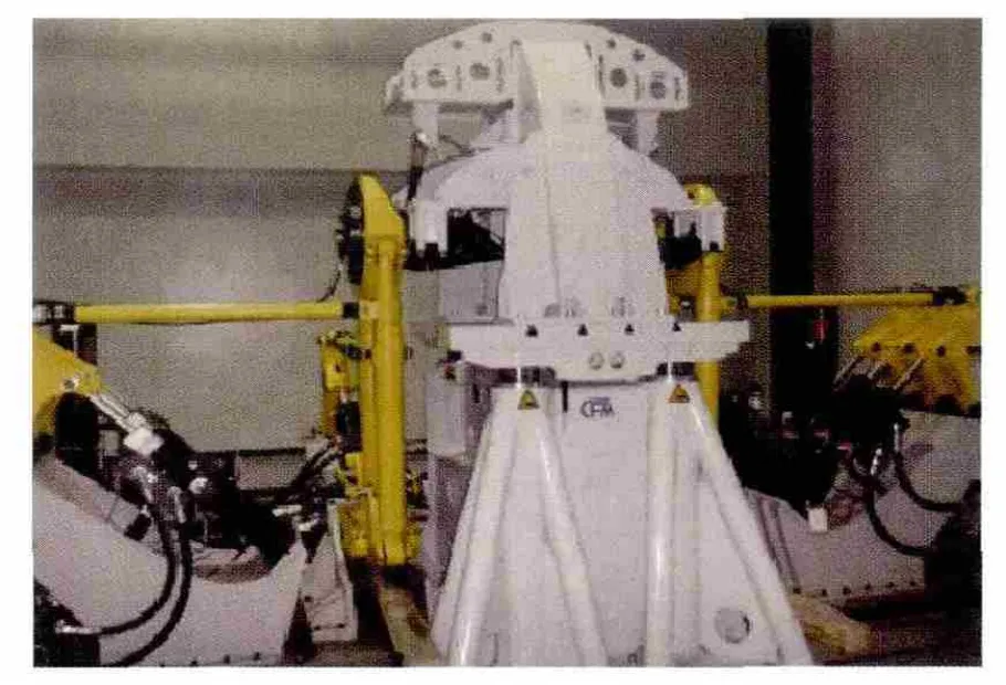
Fig.9.Test set-up of rear axle

Table 4.Comparisons of fatigue lives and test life of rear axle
4 Discussion
The accuracy of the proposed model could be evaluated by comparing the calculated lives with experimental lives.All values for predicted and experimental lives of half shaft and rear axle are summarized and correlations between them are presented in Fig.10.
For the two examples,predicted lives based on different methods are all conservative compared with experimental lives,and LALS is of the highest accuracy.The other three methods are of poor accuracy.Though PMR is of high accuracy for assessment of half shaft,it fails for rear axle.Comparisons and discussions are made as follows.
(1)Comparison of LALS with PMR.The fatigue life calculated with PMR uses only the loads above fatigue limit,while those below fatigue limit was ignored.However,according to LALS,loads are of strengthening effect before reaching the best strengthening number of cycles Nband of damaging effect after it.In the application of half shaft,the strengthening load(level 5)first caused an increase in fatigue strength in stage I(208 repetitions of loading block),then causes damage in stage II(906 repetitions).The strengthening and damaging counteracted each other,resulting in an accurate prediction.With regard to the rear axle,the strengthening effect of load level 6 continues for 454 repetitions of loading block,leaving only 47 repetitions in stage II.The damage effect caused by strengthening is much smaller than strengthening effect,resulting in a net increase of fatigue strength.PMR neglects the increase of fatigue strength,leading to a much more conservative prediction.
(2)Comparison of LALS with MMR.The fatigue lives of half shaft and rear axle predicted according to PMR are carried out by extending the S-N curve with a slope k′=k and k′=2k-1 below the fatigue limit.Due to damage effect of loads below fatigue limit was taken into account,fatigue lives predicted based on MMR are more conservative than PMR,not to mention with LALS.It should be noted that,with regard to the rear axle,the fatigue lives predicted according to MMR using an extending slope k′=k and k′=2k-1 are close;while to the half shaft,they are of great difference.That’s because the damage caused by loads below fatigue in the spectrum of rear axle takes up a small proportion,about 1.7%(k′=2k-1)and 3.8%(k′=k),while in the spectrum of half shaft,it takes up a large proportion,to 10.7%(k′=2k-1)and 27.6%(k′=k).
5 Conclusions
(1)A method for the fatigue life prediction under service load was introduced considering LALS based on PMR.In this method,the fatigue process was divided into two stages by the best strengthening number of cycles Nbaccording to the characteristics of low-amplitude-load strengthening(LALS).
(2)The LALS method was validated by fatigue tests of two vehicle components,half shaft and torsion beam rear axle,under service loadings.The percentage errors of the predicted life with proposed method to test lives of the two examples were-3.78% and-1.76% separately.
(3)Traditional methods,such as PMR and MMR will lead to more conservative predictions for both the half shaft and rear axle compared with LALS.
(4)Using the new method,lightweight design can be further achieved in the design stage,because a lower safety factor can be selected due to higher accuracy of fatigue life prediction.
[1]LEE Y L,PAN J,HATHAWAY R,et al.Fatigue testing and analysis:theory and practice[M].Boston:Butterworth-Heinemann,2005.
[2]SCHUTZ W.A history of fatigue[J].Engineering Fracture Mechanics,1996,54(2):263–300.
[3]WIRSCHING P H,PAEZ T L,ORTIZ K.Random vibrations:theory and practice[M].New York:Courier Dover Publications,2006.
[4]LEE Y L,LU M W,SEGAR R C,et al.Reliability-based cumulative fatigue damage assessment in crack initiation[J].International Journal of Materials and Product Technology,1999,14(1):1–16.
[5]FRICKE W.Fatigue analysis of welded joints:state of development[J].Marine Structures,2003,16(3):185–200.
[6]SCHIJVE J.Fatigue of structures and materials[M].New York:Springer,2008.
[7]HAIBACH E.Modified linear damage accumulation hypothesis accounting for a decreasing fatigue strength during increasing fatigue damage[R].Fraunhofer Institute for Structural Durability-LBF,Darmstadt,1970.
[8]SCHUTZ W.The prediction of fatigue life in the crack initiation and propagation stages-a state of the art survey[J].Engineering Fracture Mechanics,1979,11(2):405–421.
[9]HOBBACHER A.Recommendations for fatigue design of welded joints and components[M].New York:Welding Research Council,2009.
[10]STANZL S E,TSCHEGG E K,MAYER H.Lifetime measurements for random loading in the very high cycle fatigue range[J].International Journal of Fatigue,1986,8(4):195–200.
[11]SONSINO C M,FRICKE W,DE BRUYNE F,et al.Notch stress concepts for the fatigue assessment of welded joints–background and applications[J].International Journal of Fatigue,2012,34(1):2–16.
[12]LIN K Y,HWANG J R,CHANG J M.Accelerated durability assessment of motorcycle components in real-time simulation testing[J].Proceedings of the Institution of Mechanical Engineers,Part D:Journal of Automobile Engineering,2010,224(2):245–259.
[13]FRICKE W,KAHL A.Comparison of different structural stress approaches for fatigue assessment of welded ship structures[J].Marine Structures,2005,18(7):473–488.
[14]XU Gang,ZHOU Hong,CHEN Donghua.Virtual test rig-based study on fatigue life prediction[J].Journal of Tong Ji University(Natural Science),2009,37(1):97–100.(in Chinese)
[15]SINCLAIR G M.An investigation of the coaxing effect in fatigue of metals[R].Urbana:Illinois University,1952.
[16]LAWNICKI J J,CUTLER V C.Effect of under stressing and coaxing on the fatigue limit of a transverse butt-welded joint[J].Journal of Testing and Evaluation,1981,9(1):39–43.
[17]KAWAMOTO M,NAKAGAWA T,FUJIWARA M.Fatigue strength and hardness of mild steel subjected to the repeated pre-understressing[J].Journal of the Japan Society for Testing Materials,1961,10(91):294–303.(in Japanese)
[18]IKAI Y,NAKAJIMA M,NAKAGAWA T.Strain aging and fatigue limit on high purity iron[J].Journal of the Japan Society for Testing Materials,1982,31(346):644–649.(in Japanese)
[19]WANG Z,CHEN Z W.Influence of small load cycle omission on fatigue damage accumulation[C]//Proceedings of the 7th International Fatigue Congress(Fatigue’99),Beijing,China,June 8–12,1999.Beijing:Higher Education Press,1999,2:1113–1118.
[20]ZHENG Songlin.Studying the effect of low amplitude loading on fatigue life of truck front axle[J].Journal of Mechanical Strength,2002,24(4):547–549.(in Chinese)
[21]LU Xi,ZHENG Songlin.Strengthening and damaging under low-amplitude loads below the fatigue limit[J].International Journal of Fatigue,2009,31:341–345.
[22]ZHENG Songlin,YUAN Feng,FENG Jinzhi,et al.Dual-effect experiment study on strengthening and damaging under low amplitude load[J].Journal of Mechanical Strength,2009,31(6):1007–1011.(in Chinese)
[23]ZHENG Songlin,LU Xi.Microscopic mechanism of strengthening under low-amplitude loads below the fatigue limit[J].Journal of Materials Engineering and Performance,2012,21(7):1526–1533.
[24]DOWNING S D,SOCIE D F.Simple rainflow counting algorithms[J].International Journal of Fatigue,1982,4(1):31–40.
[25]SONSINO C M.Fatigue testing under variable amplitude loading[J].International Journal of Fatigue,2007,29(6):1080–1089.
杂志排行
Chinese Journal of Mechanical Engineering的其它文章
- Basic Characteristics of a New Flexible Pneumatic Bending Joint
- Effect of Spine Motion on Mobility in Quadruped Running
- Curvature Theory for Point-Path and Plane-Envelope in Spherical Kinematics by New Adjoint Approach
- Stabilizing Mechanism and Running Behavior of Couplers on Heavy Haul Trains
- Application of Improved Hybrid Interface Substructural Component Modal Synthesis Method in Vibration Characteristics of Mistuned Blisk
- Modified Pressure Loss Model for T-junctions of Engine Exhaust Manifold
