Basic Characteristics of a New Flexible Pneumatic Bending Joint
2014-02-07SHAOTiefengZHANGLibinBAOGuanjunLUOXinyuanandYANGQinghua
SHAO Tiefeng,ZHANG LibinBAO GuanjunLUO Xinyuanand YANG Qinghua *
1 Key Laboratory of E&M,Ministry of Education &Zhejiang Province,Zhejiang University of Technology,Hangzhou 310032,China
2 Engineering Training Center,China Jiliang University,Hangzhou 310018,China
1 Introduction*
In recent years,flexible fluidic actuators(hydraulic or pneumatic)have attracted more and more attentions from the robotic community,because of its amazing features.They are safe,and consisted of fewer parts,and have lower weight,lower cost,higher compliance[1].Particularly,compared to traditional rigid body robots,the compliant structures have more additional advantages,which allow them to adjust themselves to environment during contact.They can handle delicate objects without causing any damage[2].Furthermore,compared to traditional mechanisms made of articulated rigid parts,compliant structures allow the reduction of the number of parts needed for a given task[3].This is an interesting feature regarding miniaturization.
Existing flexible fluidic actuators can bend,stretch or rotate.It has to be noted that there are two ways to achieve bending.The first is based on internal chambers differently pressurized and the other one on anisotropic rigidity[4].In Ref.[5],a so-called“flexible microactuator”(FMA)was proposed by SUZUMORI,et al,which was a cylinder presenting three internal chambers.The FMA can bend in any direction thanks to appropriate pressures in the chambers.Besides,it can stretch in the axial direction when the pressure is equally increased in all chambers.
Pneumatic artificial muscle(PAM)developed in the 1950s had received special attention[6].It was consisted of two components:a silicon rubber tube and a mesh of nylon fibers.The PAM was widely used as part of artificial muscles in robotic applications(anthropomorphic design,prostheses,orthotics,and so on)thanks to its compliance and low power to weight ratio,e.g.,a parallel manipulator driven by three pneumatic artificial muscles and its parameter estimation algorithm was proposed[7–8].
In Ref.[9],a new type of PAM,named pleated pneumatic artificial muscle(PPAM)was developed as an improvement with regard to existing types of PAM.Its principle characteristic was its pleated membrane,which means it could inflate without material stretching and friction.
KONISHI,et al[10],proposed a pneumatic balloon actuator(PBA).The PBA was consisted of two flexible films.The upper one acted as a membrane and was a silicon rubber film,while the lower one played the role of a substrate and was a polyimide film.Because of this difference in the film rigidities,the PBA bended when pressurized air was introduced in.
In Ref.[11],a pneumatic actuator made of silicone rubber called“pneumatic rotary soft actuator”was proposed.This actuator acted as a rotary joint and could be used in micromanipulators and fingers.It was composed of two side plates,a sector circular arc and a pneumatic tube.When it was pressurized,its opening angle was increased and a rotation was achieved.
A flexible pneumatic actuator(FPA)was presented in Ref.[12].It was a hollow cylinder made of elastic rubber and containing a spiral steel wire.When the FPA was pressurized,the cylinder expanded in the axial direction without any other deformation thank to the spiral steel wire.When the pressure was decreased,it went back to its initial state thanks to the elasticity of the rubber.Using FPA,many types of joints had been developed,such as bending joint,3 DOFs joint and torsion joint[13].
In Ref.[14],small size flexible fluidic actuator which was referred to as EBBAs(expansion behavior based actuators)was proposed.The actuator consists of a chamber connected to two movable parts.When pressurized air was introduced,the volume and height increased,involving the movable parts to move relatively to each other.Different kinds of joints can be obtained by using EBBAs.
In this paper,a new flexible pneumatic bending joint(FPBJ)was proposed because of several drawbacks of some actuators mentioned previously.First,their load capacity perpendicular to moving plane was weak.When flexible fluidic actuators were applied in robot manipulator,the load capacity may not be satisfied.Secondly,their control strategy was an important shortcoming.Sophisticated controls were required in order to reach accurate and repeatable positioning,e.g.,GOULBOURNE[15]presented a model for a fiber reinforced dielectric elastomer actuator based on the deformation mechanism of McKibben actuators.The model was to address the limitation of actuators output force.In Ref.[16],mechanical behaviors model of pneumatic artificial muscle was proposed based on special experiments.
Thus,the new FPBJ proposed in this paper was aimed at improving the load capacity and control strategy.And the first one was improved with special anisotropic rigidity structure design.The second one was improved with its mathematical model.Furthermore,the structure influence factor was analyzed and optimized by simulation result of the mathematical model.
2 Structure Design
From the discussion above,a new FPBJ with anisotropic rigidity structure was designed.As shown in Fig.1,the new FPBJ was assembled with a plane-symmetrical rubber tube containing a spiral steel wire.Plane-symmetrical cross section instead of axis-symmetrical cross section was used in the rubber tube designed to assemble a thin spring steel piece and realize the bending movement.The spiral wire reinforced the rubber tube and prevented its deformation in the radial direction.The thin spring steel piece regarded as a non-extendable backbone was embedded in the thicker side of the rubber to reinforce the FBBJ’s stiffness,but did not affect its bending movement.Two covers closed both ends of the joint and an air feeding tube was connected to one of them.
When the FPBJ was pressurized,the rubber tube expanded in the axial direction.But the backbone and thicker side of the rubber tuber was stiffer than the other side of the rubber tube.The elongation of the rubber tube was different.The FPBJ bend towards the stiffer side.When the pressure was decreased,it went back to its initial state thanks to the elasticity of the rubber tube.
3 Mathematics Model
A simple Euler-Bernoulli beam model was suggested for modeling the new FPBJ with follow assumptions:(1)The cross-section does not change along the bending joint;(2)The Young’s modulus of the material,E,remains constant during actuation;(3)Coupling effect between the rubber tube and the spiral steel wire is neglected.
When the FPBJ was filled with compressed air,a tensile force Fpin the center of pressure was caused by increasing internal pressure p,as shown in Fig.2.During actuation,the rubber tube was considered as two parts,the thin spring steel piece and the rubber tube.Because the thin spring steel piece’s Young’s modulus E1is far more than the rubber tube’s Young’s modulus E.The steel piece’s elongation is neglected.So the neutral axis which removed from the center of pressure by a distance d was located on the steel piece.The rubber tube was elongated,and a tensile force Fbwas caused.Meanwhile,an external force Fwas introduced into the system.The F on the top of the FPBJ presented its load capacity.So the FPBJ’s force equilibrium equations on the thin spring steel piece could be defined as follows:

where Fh—Force on the thin spring steel piece,
patm—Atmospheric pressure,
r0—Average radius of rubbertube.
Meanwhile,bending moment Mp,Mb,Mwere caused by Fp,Fb,F on the thin spring steel piece respectively.According to moment equilibrium theory,Eqs.(3)and(4)was derived:

where Mh—Moment on the thin spring steel piece.
The bending moment Mhdeflected the FPBJ along circular arc.And bending radius was defined as R,the bending angle was defined as θ.When the FPBJ was deflected,the rubber tube’s radial deformation could be neglected[17].This implied that average radius of the rubber tube was not changed at the same time.So the rubber tube’s wall-thicknesstψatdψcould be derived from Eq.(5)according to Fig.3:
where L0—Initial length of the rubbertube,
t0—Initial wall-thickness of the rubber tube,
Lψ—Length of the rubber tube at dψ.
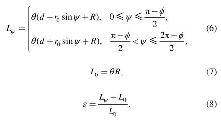
According to Fig.2 and Fig.3,Lψcould be defined in Eq.(6).So the average strain ε of the rubber tube atdψ was derived in Eq.(8):
So tensile force dFbat dAcould be derived in Eq.(9),according to Hook’s law:

Substituting Eqs.(5),(6)and(8)into Eq.(9),expression ofdFbandMbwas derived in Eqs.(10),and(11).And substituting Eqs.(2),(4),(11)into Eq.(3),Mhcould be derived:

According to Euler-Bernoulli beam model,the relationship between bending radius R and bending moment Mhwas defined in Eq.(12):

where I—Thin spring steel piece’s inertia moment.
Hence,when external moment was equal to zero,substituting Eqs.(3),(7)into Eq.(12),the joint’s mathematics model could be defined as follows:


4 Structure Parameters Analysis
According to Eq.(13),the bending angle θ was determined by P,L0,t0,r0,d,E1,E0.Among them,Pwas the motivation of the joint’s bending.So the relationship between the P and θ was analyzed firstly.And L0,t0,r0,d were structure parameters which affected the FPBJ’s performance and structure.The FPBJ could be optimized by analyzing them.In following further discussion,the mathematical model equation(Eq.(13))was simulated.And the simulation parameters were shown in Table 1.
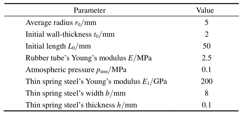
Table 1.Simulation parameters of bending joint
4.1 Internal air pressure influence
According to Table 1,the bending angle θ of FPBJ as mentioned before was simulated by increasing the internal pressure p(0.1–0.6 MPa).As was shown in Fig.4,the behavior of the bending angle was according to the air pressure within the FPBJ.It can be seen that the bending angle increased as the air pressure in the FPBJ increased.But the relationship was nonlinear.

Fig.4.Plot of bending angle against the internal pressure
4.2 Joint’s length influence
Without changing other parameters,the bending angle θ was simulated by increasing the FPBJ’s length0L(50–100 mm).And Fig.5 showed that under the same internal air pressure,the relationship between the joint bending angle and length was linear.And the slope increased with increase of internal air pressure.The bending angle increased as the length increased.

Fig.5.Relationships between length and bending angle
4.3 Joint’s radius influence
With the same method,the bending angle θ was simulated by increasing the FPBJ’s radius r0(5–10 mm).As Fig.6 showed that when internal air pressure p≤0.3MPa,the joint radius r0had almost no effect to the bending angle.When 0.3MPa<p<0.5MPa,the relationship between joint’s radius and bending angle is linear.The bending angle increased with the increase of the joint radius.But,when p>0.5MPa,the relationship tended to be nonlinear.

Fig.6.Relationships between joint radius and bending angle
4.4 FPBJ’s wall-thickness influence
The bending angle θ was simulated by increasing the FPBJ’s wall-thickness t0(1.5–5 mm).Fig.7 showed that the joint bending angle decreased with increase of joint’s wall-thickness.When t0≤3mm,the effect was particularly obvious and the relationship was nonlinear.When t0>3mm,the FPBJ was difficult to bend.And the relationship was linear under the same air pressure.The wall-thickness influence increased as the air pressure increased.

Fig.7.Relationships between wall-thickness and bending angle
4.5 Thin spring steel piece influence
The bending angle was affected by the thickness of the thin spring steel piece h.The relationship was simulated by increasing the h(0.05–0.5 mm).As Fig.8 shown,θ decreased with increase of the h under the same air pressure.When p≤0.2MPa,the thickness influence was weak.When p>0.2MPa,the thickness influence was stronger.When h≤0.25mm,the influence was nonlinear,but when h>0.25mm,the effect was close to linear.

Fig.8.Relationships between spring steel’s thickness and bending angle
5 Experimental Analysis
5.1 Experimental scheme
According to the simulation results discussed above,the joint’s structure parameters were optimized.As an example,three FPBJs were manufactured and tested with following parameters:r0=5 mm,t0=2 mm,L0=40/60/80 mm,h=0.2 mm.A photograph of a prototype FPBJ is shown in Fig.9.
The experimental setup illustrated in Fig.10 was capable of providing real-time data acquisition of the FPBJ bending angle and the air pressure within the FPBJ.A flexible sensor(FLX-03)was used to observe the FPBJ bending angle.With this sensor,the bending angle could be measured easily without affecting joint’s actuation and size.And a proportional valve was used to provide and observe the air pressure in the FPBJ.The data was interfaced to the embedded system through ADC and DAC.

Fig.9.FPBJ photograph
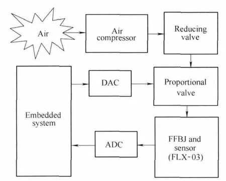
Fig.10.Experimental scheme diagram
5.2 Experimental results
Two experiments have been carried out.The first one was carried out when external force was equal to zero.And the result was shown in Fig.11 with the simulation result.The test was repeated in order to determine the repeatability.And the maximum internal air pressure was limited to 0.5 MPa.The two results were compared and it showed that the maximum relative error between simulation and experimental results was less than 6% when the FPBJ was deflated.But when the joint was inflated,the maximum relative error reached 20%.
The second one was carried out when external force 0≤F≤7N.And two FPBJs with different length were tested.The length of FPBJ1 was 60 mm,and the length of FPBJ2 was 80 mm.Four typical sets of data were chosen and shown in Fig.12.As shown in Fig.12,under the same external force,when the FPBJs were inflated,the bending angle of FPBJ2 was smaller than the one of FPBJ1 at the beginning.As the pressure increased,bending angle of FPBJ2 increased much faster,and it was larger than the FPBJ1’s angle at last.However,the simulation result indicated that FPBJ2’s bending angle should always be larger than the FPBJ2’s bending angle under the same external force.
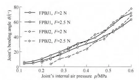
Fig.12.The second experiment data
6 Conclusions
(1)The new flexible pneumatic bending joint with plane-symmetrical symmetrical structure proposed in this paper is flexible and safe.It is especially suitable for agricultural robot and service robot.The joint’s mathematical model was derived based on Euler-Bernoulli beam model and Hook’s law,which gave an effective description to understand the mechanical behavior of the FPBJ.The simulation results provided an important reference for structure design.
(2)Experiment results showed that the joint’s statics characteristics were reflected by the mathematical model accurately.However,limitations still existed.For instance,in the first experiment,when the joint was inflated,the maximum relative error was much larger than expected;in the second experiment,the length influence reflected in the model was inaccurate at the beginning of the experiment.That was because the mathematical model was based on perfect rubber and air.During modeling,rubber viscosity and air compressibility were ignored.The viscoelastic rubber has nonlinear creep deformation behavior,which means its deformation is not only affected by tension,but also affected by temperature and time.At the beginning of the experiment,the FPBJ’s deformation was hindered by the viscosity.And errors were accumulated.But with the passage of time,the error reduced gradually.When the FPBJ was deflated,the viscosity affected the joint in the same way.Thus,the experimental data was always less than the simulation data.
Further study is necessary to reconcile following problem.
(1)More complicated external forces which may cause the FPBJ to move out of the bending plane should be taken into account.
(2)Intelligent control algorithm such as neural networks may be introduced to simplify and improve the mathematics model.Since the mathematics model obtained in this paper was too complex to compute in real time.
[1]SHAPIRO Y,WOLF A,GABOR K.Bi-bellows:Pneumatic bending actuator[J].Sensors and Actuators A:Physical,2011,167(2):484–494.
[2]BERRERRO A M,RURRIU M.A novel fluidic bellows manipulator[J].Robot Mechatron.,2004,16(6):604–612.
[3]HOWELL LL.Compliant mechanisms[M].New York:Interscience;Press,2001.
[4]ALLINE De GREEF,PIERRE LAMBERT,ALAIN DELCHAMBRE.Towards flexible medical instruments:Review of flexible fluidic actuators[J].Precision Engineering,2009,33(4):311–321.
[5]SUZUMORI K,IIKURA S,TANAKA H.Development of flexible microactuator and its applications to robotic mechanisms[C]//Proceedings of the 1991 IEEE International Conference on Robotics and Automation,1991:1622–1627.
[6]ZHANG Libin,BAO Guanjun,YANG Qinghua,et al.Review on flexible pneumatic actuator and its application in dexterous hand[J].China Mechanical Engineering,2008,19(23):2891–2897.(in Chinese)
[7]TAO Guoliang,ZHU Xiaocong,CAO Jian.Modeling and controlling of parallel manipulator joint driven by pneumatic muscles[J].Chinese Journal of Mechanical Engineering,2005,18(4):537–541.
[8]TAO Guoliang,ZHU Xiaocong,CAO Jian.Parametric identification of parallel manipulator with redundancy driven by pneumatic muscles[J].Chinese Journal of Mechanical Engineering,2008,21(1):66–68.
[9]FRANK DAERDAN,DIRK LEFEBER.The concept and design of pleated pneumatic artificial muscles[J].International Journal of Fluid Power,2001,2(3):1–5.
[10]KONISHI S,KAWAI F,CUSIN P.Thin flexible end-effector using pneumatic balloon actuator[J].Sensors and Actuators A:Physical,2001,89(1):28–35.
[11]NORITSUGU T,KUBOTA M,YOSHIMATSU S.Development of pneumatic rotary soft actuator made of silicone rubber[J].Robot Mechatron.,2001,13(1):17–22.
[12]YANG Q,ZHANG L,BAO G,et al.Research on novel flexible pneumatic actuator FPA[C]//Proceedings of the 2004 IEEE Conference on Robotics,Automation and Mechatronics,2004,1:385–389.
[13]ZHANG Libin,BAO Guanjun,YANG Qinghua,et al.Static model of flexible pneumatic torsion joint[J].Chinese Journal of Mechanical Engineering,2008,44(7):134–138.(in Chinese)
[14]SCHULZ S,PYLATIUK C,BRETTHAUER G.A new ultralight anthropomorphic hand[C]//Proceedings of the 2001 IEEE International Conference on Robotics and Automation(ICRA 2001),2001:2437–2441.
[15]GOULBOURNE N C.A mathematical model for cylindrical,fiber reinforced electro-pneumatic actuators[J].International Journal of Solids and Structures,2009,46(5):1043–1052.
[16]KANZHANA C,THANANCHAI L.Study on mechanical behaviors of pneumatic artificial muscle[J].International Journal of Engineering Science,2010,48(2):188–198.
[17]BAO Guanjun.Research on characteristics of flexible pneumatic actuator FPA and its application in multi-fingered dexterous hand design[D].Hangzhou:Zhejiang University of Technology,2006.(in Chinese)
杂志排行
Chinese Journal of Mechanical Engineering的其它文章
- Effect of Spine Motion on Mobility in Quadruped Running
- Curvature Theory for Point-Path and Plane-Envelope in Spherical Kinematics by New Adjoint Approach
- Fatigue Life Prediction under Service Load Considering Strengthening Effect of Loads below Fatigue Limit
- Stabilizing Mechanism and Running Behavior of Couplers on Heavy Haul Trains
- Application of Improved Hybrid Interface Substructural Component Modal Synthesis Method in Vibration Characteristics of Mistuned Blisk
- Modified Pressure Loss Model for T-junctions of Engine Exhaust Manifold
