Stabilizing Mechanism and Running Behavior of Couplers on Heavy Haul Trains
2014-02-07XUZiqiangWUQingLUOShihuiMAWeihuaandDONGXiaoqing
XU Ziqiang *,WU Qing ,LUO ShihuiMA Weihuaand DONG Xiaoqing
1 Traction Power State Key Laboratory,Southwest Jiaotong University,Chengdu 610031,China
2 Locomotive and Car Research Institute,China Academy of Railway Sciences,Beijing 100081,China
3 Centre for Railway Engineering,Central Queensland University,Rockhampton,Queensland QLD4701,Australia
1 Introduction*
Due to the large tonnage of heavy haul trains,in-train forces generated are unsurprisingly large,especially when trains are under braking conditions.Longitudinal forces could cause rotations of couplers and result in large lateral components which exert adverse effects to running safety of trains.A number of derailments happened on heavy haul trains,which were caused by large lateral components generated by longitudinal coupler forces.Theoretical studies and field test indicate that derailments of such are usually caused by excessive rotation angles of couplers[1–4].
Detailed coupler and draft gear models are required to analyze coupler rotational behavior and the corresponding effects.Some studies have already been done in this regard.Some simplified models consider coupler systems as spring/damper force elements.Models of this type were conventionally used in longitudinal train dynamics simulations.Simplified models have advantages in regard to computational efficiency but cannot be used to analyze the behaviors of couplers[5–6].Another type of models which calculates the lateral components of coupler forces firstly,and then apply the calculated lateral forces on train dynamics models.For instance,El-SIBIE[7]developed a coupler angle calculation program called the Coupler Angling Behavior Simulator which applied the lateral components to a train dynamic model,and investigated the safety of trains on a section of curved track.COLE,et al[8–9],calculated the coupler angles and longitudinal forces;then the lateral components of coupler forces are calculated and applied to train dynamic models.The quasi-static lateral forces,quasi-static vertical forces and quasi-static bogie lateral to vertical ratio have been studied.LUO,et al[10],calculated the coupler forces,and then compared the differences of hunting stability between train systems and single vehicles.The shortcoming for the second type models is that couplers’implications were the input characteristics which cannot reflect the actual behaviors of couplers during train simulations.A detailed type of coupler system model considers couplers as rigid bodies which have the rotational DOF(degree of freedom).This type of model has been used to research the real time behaviors of coupler systems and their effects.LUO,et al[11]and MA,et al[12],constructed detailed coupler models in which the coupler structure and rotation limit were considered.Based on this model,coupler rotational behaviors and locomotive safety problems under the braking condition have been studied.XU,et al[13–15]and WU,et al[16–17],improved the LUO’s model[11],which has considered the hysteretic draft gear model and friction-pair coupler,the running behaviors of the couplers under different conditions had been analyzed.
This paper analyzes structures and stabilizing mechanisms of two typical coupler systems.The particular dynamic models of these two types of coupler systems have also been developed and applied in train models.The analyses include the rotational behavior of two couplers and its influence on the locomotive running safety on the tangent and curved track.Also,this paper gives some suggestions to the design of coupler and draft gear systems in heavy haul trains.
2 Coupler System Models
2.1 Coupler stabilizing mechanism
Two typical coupler systems are shown in the Fig.1.The type A coupler system has the round pin,which means the coupler body can rotate freely around pin.Therefore,coupler shoulder and plunger casting devices have been set,which have the stable-control function to the coupler rotational behavior(Fig.1(a)).When the coupler shoulder and plunger casting contact,the draft gear force provides the supporting force and constrains the further rotation of the coupler.The type A system is usually called round-pin coupler systems,example couplers are the 102 type coupler,the DFC-E100 type coupler etc.The type B coupler system is called the flat-pin coupler and has a completely different stable-control function compared with the round-pin coupler.The vertical flat-key in the type B system not only provides connections between coupler body and yoke but also act as the stop because of the fan-shaped key slot as shown in Fig.1(b).Besides,friction pairs between coupler butts and followers can provide friction forces and constrain the rotation of coupler when the coupler subjected to the compressive forces.The type B system is also equipped with suspender which takes advantage of the gravity to align couplers.
When coupler systems are subjected to compressive forces,moments which tend to enlarge the coupler angles are termed“overturn moment”in this article,and those who try to constrain the rotations of couplers are termed“aligning moment”.Coupler angles which are allowed for couplers to rotate freely without aligning moment is termed“free-angle”of the type A coupler system.The maximum coupler angle allowed for couplers to rotate without structural interference on the carbody is termed“max-angle”.
Using the above definitions,overturn moments of the two types of coupler systems in Fig.1 can be expressed by
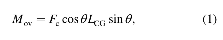
where Movis the overturn moment,N•m;LCGis the coupler length,m;Fcis the coupler force,kN;θ is the coupler angle,rad.
In comparison,aligning moments have far more complicated situations.For type A systems,the variations of aligning moments can be divided into four phases:(i)coupler angles are within the free-angle;(ii)coupler shoulders just contact with the plunger casting;(iii)coupler angles exceeded the free-angle but within the max-angle;(iv)coupler angles reached the max-angle.Aligning moments of different phases are expressed by
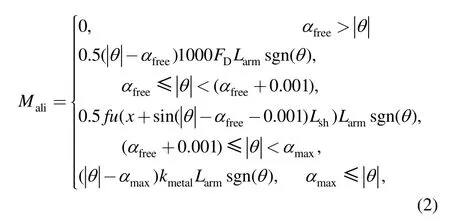
where FDis the draft gear force,N;fu is the function of draft gear loading characteristics;x is the draft gear stroke,m;Larmis the arm of aligning moments,m;Fcsis the coupler shoulder force,N.
It is important to note that before coupler angle reaches the free-angle,a draft gear device could has already been compressed,which means that the coupler system already provides a certain aligning-control force.This force can be taken as a pre-load on plunger casting.The coupler cannot rotate further until the plunger force exceeds the pre-load.In order to address the discontinuity of the pre-load in modeling,this phase is described by a small range(0.001 rad)Ramp Function.
The concept of free-angle in type B systems no longer exists.Thus,variations of aligning moments in type B system should only be divided into 2 phases:
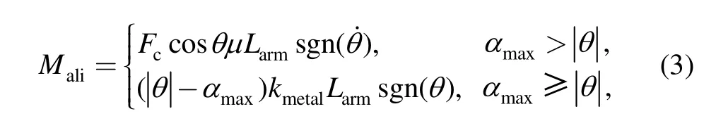
where μ is the friction coefficient of friction pairs.
2.2 Draft gear devices model
There are various approaches on the draft gear modeling[18–22],the look-up table approach is one of the accurate and stable approach.Two types of draft gear devices are modeled by using the look-up table approach.First,the characteristics of draft gears are obtained by tests,such as drop hammer test,static or impact test.Then,the results are used to develop loading and unloading functions,and the impedance force of draft gear is gained from its stroke.Two draft gears’test results are shown in Fig.2 and Fig.3.
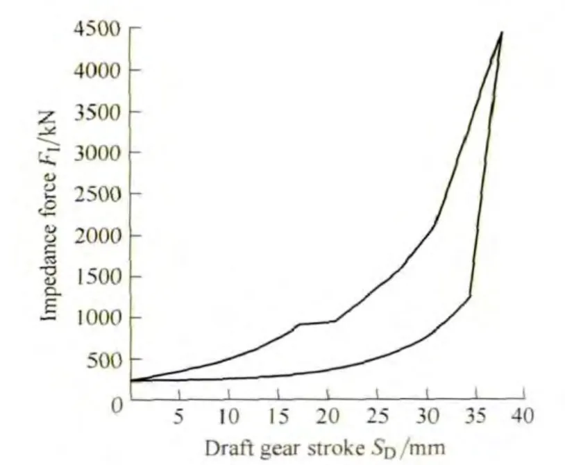
Fig.2.Test results of type A draft gear
According to characteristics of draft gears,their models are expressed mathematically by
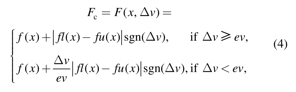
where Δv is the stroke change velocity of the draft gear,the ev is the switching rate of draft gear.fl(x)and fu(x)is the draft gear loading and unloading function.f(x)is relevant to fl(x)and fu(x).When the draft gear reaction is in the loading state(Δv>0),f(x)=fl(x).When the draft gear reaction is in the unloading state(Δv<0),f(x)=fu(x).
The impact and static compression simulations of two kinds of draft gears are shown in Fig.4.The type A draft gear has larger impedance force and shorter stroke,the maximum values are 4400 kN and 38 mm,respectively.The type B draft gear has smaller impedance force and longer stroke than that of type A draft gear,the values are 2500 kN and 82 mm,respectively.When the compressive force reaches 3000 kN,there is a rigid impact and the draft gear loses its damping function(Fig.4(b)).The type A draft gear can provide larger aligning forces from coupler shoulder within a short stroke,but has poorer damping capacity.On the contrary,the draft gear in the type B system has better damping capacity and longer stroke,but the maximum impedance force is small.The simulation results reasonably reflect the hysteretic characteristics and the damping capacities of two types of draft gear devices which also in accordance with the test results in Fig.2 and Fig.3,so the draft gear simulation models are accurate.
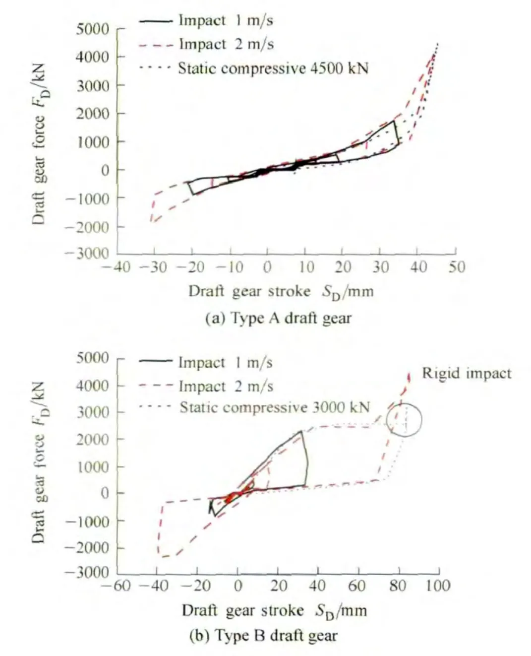
Fig.4.Impact and static compression simulations
2.3 Coupler systems
The coupler systems mainly consist of a coupler body,two draft gears and two followers.Coupling slack between couplers has been considered in the draft gear stroke,so the coupled couplers are simplified as one rigid body.The coupler and draft gear system models are shown in Fig.5.
The coupler is connected with the follower and has the freedom of rotation around Z axis at points A and B;while the follower is connected with the car body and has a freedom of translation in X axis.Points A and B are integrated with coupler shoulder stable-control characteristics or friction pairs and stop characteristic.
3 Train Model
The train model consists of two locomotives and two wagons which are connected by the previously described coupler system models(Fig.6).The longitudinal in-train forces are applied on the two wagon bodies,which have the same values but in opposite directions.This train model simulates the remote locomotives and adjacent wagons which generally have the worst force conditions in the entire heavy haul train.Interested targets are coupler systems locate between two locomotives and the adjacent two wheelsets(The 4th wheelset of locomotive A and the 1st wheelset of locomotive B).
The studied locomotive is a new type heavy haul locomotive,the axle-load of the locomotive is 30 t using the B0-B0 axle configuration.The axle-load of this locomotive raise 20% compare with conventional 25 t axle-load heavy haul locomotives.According to parameters of the locomotive,the dynamic model of a single locomotive has been built with 1 car body,2 bogies,4 wheelsets,4 motors,4 motor rods and 2 traction rods.These seventeen rigid bodies have 50 DOFs(degree of freedoms),bogies and carbody have 6 DOFs,wheelsets have 4 DOFs,motor rods and traction rods have 2 DOFs,motors have 1 DOF.All suspensions and nonlinear dampers have been considered.The wagon models are conventional C80 wagons which will not be described in detail.
Simulated locomotives use standard-gauge railway bogies.The gauge distance is 1435 mm.The wheel tread is a JM3 worn-type tread,and the rail weigh is 75 kg.During the simulations,the speed of the train is 100 km/h on tangent track and 60 km/h on the curved track.Since there are no real measured heavy-haul track irregularities in China,the commonly used American class 5 track irregularities are adopted for the model.The key parameters of the train model are listed in Table 1.
4 Simulation Results
4.1 Tangent condition
On tangent tracks,compressive forces are step-shaped and are used to simulate the effect of different force conditions.Coupler angles and wheelset lateral forces are calculated.
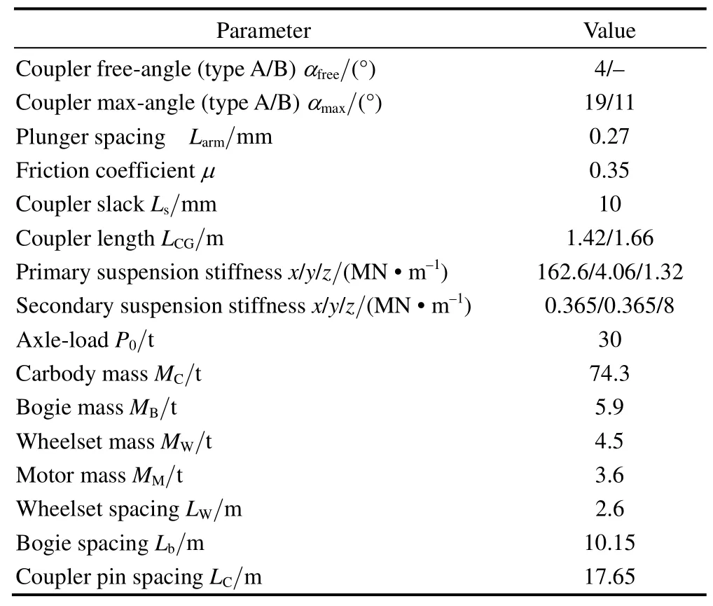
Table 1.Key parameters of train model
Fig.7 shows the relationship between coupler angles and compressive forces.The rotation performances of the two types of coupler systems are significantly different.The type A coupler rotates to the free-angle after compressive force is larger than the carbody stable-ability.Subsequently,since the stiffness of coupler shoulder,the coupler angle only has a very slight increase during the continuously increase of compressive forces.The type B coupler generates friction forces when the coupler is objected to compressive forces,this friction force is also in proportion to the compressive forces and can make the type B coupler remain a dynamic stable state around zero value
Fig.8 shows the time-history of wheelset lateral forces.The figure indicates that wheelset lateral forces of locomotives,when equipped with the type A coupler system,increases significantly after the coupler rotates to the free-angle,the maximum value is 80 kN.Although the coupler shoulder constrains the further rotation of coupler and provides an aligning moment,there are lateral component forces of compressive forces act on the wheelset and make the wheelset lateral force increase.When compressive forces continue to increase,the coupler angle remains stable and the increment of overturning moment is balanced by the coupler shoulder aligning moment.Therefore,the wheelset lateral forces are almost constant during the increase of compressive forces;for the type B case,the coupler rotational angle is very small,therefore,compressive forces have little effect to wheelset lateral forces.Wheelset lateral forces affected by the track irregularity,the maximum value are 50 kN.
It should be pointed out that locomotives with different types of coupler systems have reasonable dynamic performances.Other evaluation indexes such as derailment coefficient and wheel load reduction rate share the same trend as wheelset lateral force.Derailment coefficient and wheel load reduction rate of the type A case and type B case are 0.28,0.45 and 0.2,0.39,respectively.
4.2 Curved track
The curved track is a section of S-shaped track with two reversed circular curves.The length of each circular curved track is 150 m with radii of 300 m,the length of the transition curve is 120 m,as shown in Fig.9.The elevation of the track is set at 120 mm.
When the train negotiates a curve,the carbody takes over the tangential position of the track,a relative rotation of adjacent carbodies is also generated which leads the rotation of couplers.Reversed curvatures of curves cause different rotation directions of carbodies which also affect the coupler rotation direction.That is why the S-type curve is set.There were some studies on how to calculate the natural coupler angles on the curved track[9,13],according to these studies the coupler angle of 300 m curve can be obtained,the value is 2.1°.
In order to compare the running performances of two coupler systems under idle and compressive conditions,this chapter analyzes the coupler performance when maximum compressive forces are 0 and 2000 kN,respectively.Compressive forces are acted from 0 to 2000 kN and then remained stable at 2000 kN(Fig.10).
Under the idle condition,the results show that two types of couplers both rotates to 2.1° during the curve negotiation.The results are similar to theoretical calculations;meanwhile there are some vibrations during the time-history which are caused by track irregularities.
When the compressive forces are 2000 kN,the type A coupler rotates to the free-angle and then remain stable at 4° on the tangent track.Subsequently,when the train is running into the right curve,the relative rotation directions of carbodies are opposite to the initial rotation direction of coupler.At this time,coupler reversed rotates from 4° to 1°.When the train is running into the straight line between two curves,the coupler rotates to the free-angle again.When train is running into the left curve,the relative rotation directions of carbodies are the same to the coupler rotation direction.Because of the limit effect of coupler shoulder,the coupler will not rotate a further angle,but remained stable at 4°.
The rotation performances of the type B coupler under 2000 kN compressive force is similar to results in the idle condition,the max coupler angle is 1.9°,distinctly different from the type A case.Simultaneously,coupler rotational behaviors have smaller amplitude compare with the idle case,which is because the friction forces decrease the vibration amplitude of coupler angle.
Fig.11 indicates the effect of compressive forces on wheelset lateral force.The results indicate that the maximum lateral force always happens on the steering wheelset(the 1st wheelset of the locomotive).When the compressive forces are zero,the wheelset of two cases are almost the same.When the compressive forces increase,the tendencies of wheelset lateral forces in two cases are distinctly different.When the type A case suffers the 500 kN compressive force,coupler rotates to the free-angle,and leads to a rapid increment of wheelset lateral force compares with the idle condition.Subsequently,the wheelset lateral forces increase modestly with the continuously increase of compressive force,at last the maximum wheelset lateral force is 110 kN,that means the locomotive which equips with type A coupler systems can bear with 2500 kN compressive forces;The wheelset lateral forces of the type B coupler systems are small when compressive forces are less than 1000 kN.But when compressive forces are larger than 1000 kN,the lateral components of compressive forces increase significantly and lead increments of wheelset lateral forces.When the compressive force reaches 2500 kN,the lateral force of the guide wheelset is 140 kN,exceeding the limit value 110 kN,the locomotive is at the risk of derailment.
Table 2 shows the maximum values of other two locomotive evaluation indexes.The results indicate that the derailment coefficient and wheel load reduction rate of the type A case can meet the running safety requirement,but the wheel load reduction rate of the type B case reaches the limit value 0.65 when the compressive force is 2000 kN.
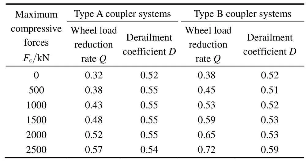
Table 2.Derailment coefficient and wheel load reduction rate on curved track
4.3 Effect of coupler shoulder stable-control on curved track
From section 4.2,the wheelset lateral forces of type A case are smaller than the type B case when compressive forces reached 2000 kN.According to the theoretical analysis,the coupler shoulder balances the overturn moment and reduces the lateral component of coupler compressive forces.This structure can improve the running safety during the curve negotiation.
When the train stables on the curved track,the state of the carbody and coupler systems is shown in Fig.12.Shoulders and plunger castings of type A couplers generate aligning forces to stop coupler rotating further,both plunger castings and coupler pins are subjected to compressive forces from couplers,in which forces apply on coupler pins are along with coupler center line,but forces apply on plunger castings are paralleled with the carbody centerline.Therefore the torque equilibrium equation can be determined:
where Fy—Lateral force on second suspension,kN,
Fp—Coupler pin compressive force,kN,
Fcs—Coupler shoulder compressive force,
Lp,Lcs—Distances of application lines of coupler pin forces and coupler shoulder forces respectively.
The variables are expressed as follows:
where β is the carbody yaw angle cause by compressive force.
For the type B coupler,the compressive forces act on coupler pins are equal with the coupler forces,therefore,Eq.(5)can be simplified to:
While on the tangent track,the type B coupler almost stable at zero,the coupler compressive forces have little effect to the wheelset.But when the train negotiates a curve,the coupler rotates a certain angle and generates a large lateral component of the coupler force which increases with the compressive force and causes adverse effects to the running safety of the train.
In conclusion,the coupler shoulder stable-control can balance part of the overturn moment,which can reduce the lateral component of coupler force and improve the running safety on the curved track;the type B coupler systems don't have the coupler shoulder device,its curving performance is worse than the type A case under large compressive force.
5 Conclusions
This paper aims at two typical coupler systems,analyzing their performances and their effects on the locomotive running safety.After the structure theory analyses and dynamic simulations,several results are obtained.
(1)The stable mechanisms of the two types of coupler systems are different.The type A coupler has coupler shoulder and plunger casting structures which have stable-control ability to constrain the further rotation of the coupler;the type B coupler has friction pairs between followers and coupler tails,the friction force can provide constraints when the coupler suffers compressive forces.
(2)When the train runs on a tangent track under compression conditions,the type A coupler rotates to the free-angle,while the type B coupler almost stable and the coupler angle remains around zero.Significant lateral components of compressive forces are generated by the type A coupler.Thus,the running performance of the type A coupler is poorer than the type B coupler.Furthermore,the train has good running safety regardless of the coupler types on the tangent track.
(3)When the line is a curved track,the rotation performances of two types of couplers differ from those on the tangent track.The type A coupler provides a large aligning moment when coupler shoulder contacts with plunger casting,which decreases the lateral components of coupler compressive forces and improves the curving performances of the train;the lateral components in type B coupler all pass to wheelsets,which reduce the curving performances of the locomotive.When compressive force reaches 2000 kN,the locomotive,which equips type B coupler system,is at the risk of derailment.
To sum up,the two types of coupler and draft gear systems have their own advantages and disadvantages,combining the advantages of these two coupler systems can reduce the train derailment risk caused by coupler rotational behaviors.This is the development directions to improve heavy haul coupler systems.
[1]Canadian National.Railway investigation report of derailment[R].Rep.R02C0050.TSB Canada,2002.
[2]WANG Kaiyun,ZHAI Wanming,FENG Quanbao,et al.Effect of the coupler free angle on wheel/rail dynamic safety performance of heavy haul locomotive[J].China Railway Science,2009,30(6):72–76.(in Chinese)
[3]CHEN D.Derailment risk due to coupler jack-knifing under longitudinal buff force[J].Journal of Rail and Rapid Transit,2010,224(363):483–490.
[4]LI Gu.The summary report of experiments for the type HXD2 locomotive equipped with type DFC-E100 coupler system[R].Research Report of China Academy of Railway Sciences(CARS),No.2008-JL-36,Beijing,July 2008.(in Chinese)
[5]NASR A,MOHAMMADI S.The effects of train brake delay time on in-train forces[J].Journal of Rail and Rapid Transit,2007,224(306):523–534.
[6]IWNICKI S.Handbook of railway vehicle dynamics[M].CRC Press,Taylor &Francis Group,Boca Raton,FL,2006.
[7]EL-SIBAIE M.Recent advancements in buff and draft testing techniques[C]//Fifth International Heavy Haul Conference,Bejing,China,1993:115–119.
[8]COLE C,SUN Y Q.Simulated comparisons of wagon coupler systems in heavy haul trains[J].Journal of Rail and Rapid Transit,2006,220(35):257–256.
[9]COLE C,McCLANACHAN M,SPIRYAGIN M,et al.Wagon instability in long trains[J].Vehicle System Dynamic Supplement,2012,50:303–317.
[10]LUO Ren,ZENG Jing.Hunting stability analysis of train system and comparison with single vehicle model[J].Journal of Mechanical Engineering,2008,44(4):184–188.(in Chinese)
[11]LUO Shihui,FENG Quanbao,YANG Junjie.Research on dynamics of the HXD2 heavy locomotive bearing longitudinal compressive strength[J].Railway Locomotive&Car,2008,28:145–149.(in Chinese)
[12]MA Weihua,LUO Shuihui,SONG Rongrong.Coupler dynamic performance analysis of heavy haul locomotives[J].Vehicle System Dynamic,2012,50(9):1–19.
[13]XU Ziqiang,LUO Shihui,MA Weihua.Dynamics properties of 2B0 heavy haul locomotive based on longitudinal stress[J].Journal of Traffic and Transportation Engineering,2009,9(3):49–53.(in Chinese)
[14]XU Ziqiang,MA Weihua,WU Qing,et al.Coupler rotation behaviour and its effect on heavy haul trains[J].Vehicle System Dynamic,2013,51:1817–1838.
[15]XU Ziqiang,MA Weihua,WU Qing,et al.Analysis of the rotation angle of a coupler used on heavy haul locomotives[J/OL].Journal of Rail and Rapid Transit,2013,8.
[16]WU Qing,LUO Shihui,WEI Chongfeng,et al.Dynamics simulation models of coupler systems for freight locomotive[J].Journal of Traffic and Transportation Engineering,2012,12(3):37–43.
[17]WU Qing,LUO Shihui,XU Ziqiang,et al.Coupler jackknifing and derailments of locomotives on tangent track[J].Vehicle System Dynamic,2013,51(11):1784–1800.
[18]ANSARI M,ESMAIZADEH E,YOUNESIAN D.Longitudinal dynamics of freight train[J].International Journal of Heavy Vehicle Systems,2009,16:102–131.
[19]NASR A,MOHAMMANDI S.The effects of train brake delay time on in-train forces[J].Journal of Rail Rapid Transit,2010,6(224):523–534.
[20]DIANA G,BELFORTE P,CHELI F,et al.Numerical and experimental investigation of heavy freight train dynamic[C]//2007 ASME International Mechanical Engineering Congress and Exposition,Seattle,Washington,2007,16:1–10.
[21]BELFORTE P,CHEL F I,DIANA G,et al.Numerical and experimental approach for the evaluation of severe longitudinal dynamics of heavy freight trains[J].Vehicle System Dynamic,2008,46:937–955.
[22]ZHANG Suohuai,MENG Xu.Nonlinear impacting dynamic model of a metro vehicle[J].Journal of Mechanical Engineering,2012,48(9):111–116.(in Chinese)
杂志排行

Chinese Journal of Mechanical Engineering的其它文章
- Wear Analysis of Disc Cutters of Full Face Rock Tunnel Boring Machine
- Experiment on Wear Behavior of High Pressure Gas Seal Faces
- Dimensional Description of On-line Wear Debris Images for Wear Characterization
- Temperature Distribution and Scuffing of Tapered Roller Bearing
- Case-Based Reasoning(CBR)Model for Ultra-Fast Cooling in Plate Mill
- Development of Evaluation Technique of GMAW Welding Quality Based on Statistical Analysis