Experiment on Wear Behavior of High Pressure Gas Seal Faces
2014-02-07XUJingPENGXudongBAIShaoxianMENGXiangkaiandLIJiyun
XU Jing ,PENG Xudong *,BAI ShaoxianMENG Xiangkaiand LI Jiyun
1 MOE Engineering Research Center of Process Equipment and Its Remanufacture,Zhejiang University of Technology,Hangzhou 310032,China
2 School of Mechanical Engineering,Hangzhou Dianzi University,Hangzhou 310018,China
1 Introduction*
Spiral groove dry gas seal(S-DGS)are non-contacting,dry-running mechanical face seals which offer numerous advantages over contact mechanical seal and have been widely used in petroleum,chemistry and energy industries.The increase in operating pressures for a turbo-machinery asked for an improved geometrical design of such a S-DGS so as to avoid face wear caused by mechanical deformation of seal rings.So the study of seal deformation has become a hotspot at home and abroad.
The effects of surface micro-scale sizes and the thermal viscosity on performance of a S-DGS have been studied by XU,et al[1–2]with a numerical solution of a corrected Reynolds equation.Further numerical study(XU,et al[3])found that the influence of different constructions,sizes and positions of O-ring secondary seals on deformation of a S-DGS with typical seal rings was important.The theoretical researches of face distortion were initially based on the circle theory as documented by MAYER[4],he found that the modulus of elasticity and structure parameters are the main influence factors.Also the effect of face deformation on sealing performance of a mechanical seal has proven important by the other researchers[5–11],especially when the deformation causes the fluid film gap between the sealing faces to be divergent clearance under high pressures.LEBECK[12]studied the deformation of a mechanical face seal caused by various loads using a variety of calculated methods.Moreover,a new abrasion measurement technology(PHILIP,et al[13],WEN,et al[13])for sealing face wear was put forward,and the numerical calculation results were consistent with the experimental results.PENG,et al[15–16],and GU,et al[17],discovered the regularities of seal ring structures affecting face deformation.After considerable research,THOMAS,et al[18],and GREEN,et al[19],presented that the influence of deformation on sealing performance was great importance.
Research results presented in the above studies show that the pressure deformation makes seal clearance decrease at the high pressure side of a mechanical face seal,which means that face wear occurs more seriously at the high pressure side than that at the low pressure side.However,there is still lack of published experimental works enough to prove the theoretical results.The aim of this paper is to experimentally study seal face wear of a S-DGS operating under high pressure only due to the pressure deformation,in which face structure is considered as one of the major factors affecting seal deformation and the measurement of optical images and profiles of sealing surface is proposed so as to provide evidence for the theoretical study.
2 Experimental Details
A test rig for examining seal face wear of a S-DGS operating under high pressures was designed as shown in Fig.1.The stator of the tested S-DGS was fixed into a metallic holder.The rotor the tested S-DGS was fixed into another metallic holder on the axle sleeve of the shaft,which was driven by a motor at a certain rotation speed.An eddy current displacement sensor was fixed together with the stator and a stainless steel sheet was fixed into the rotor so as to measure the average gas film thickness.The seal clearance was got by measuring the displacement change between the eddy current displacement sensor and the stainless steel sheet during testing.The leakage rate of sealed gas was measured by a leakage rate sensor.The sealed gas provided by a nitrogen gas steel container can flow into the seal housing controllably,in which the gas pressure was adjusted by a pressure valve and measured by a pressure sensor.The collection and processing of the test data of seal clearance,leakage rate,and sealed gas pressure were made by using a data acquisition and processing system.Before testing,all the samples were cleaned in an acetone bath ultrasonically for 5 min.When a test was over,the tested stator and rotor were new alternative.
Theoretically,the minimum film gets smaller due to the existence of secondary O-ring seal.When the position of secondary O-ring seal is away from seal face,the influence of deformation on seal performance plays a greater role than that the position of secondary O-ring seal is close to the seal face.Meanwhile,size effects in the deformation of seal rings are significantly and then affect seal performance.All these effects are attributable to the values of the high pressure area and cross-sectional area of seal rings as shown in Fig.2.In this paper,the stator with two different sizes and O-ring secondary seal with two different positions were selected and tested in order to study the effects of structure and constraint on face deformation and seal performance.

Fig.2.Schematic diagram of face deformation of a test ring under high pressures
3 Results and Discussion
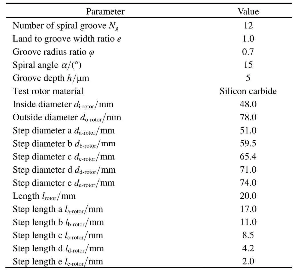
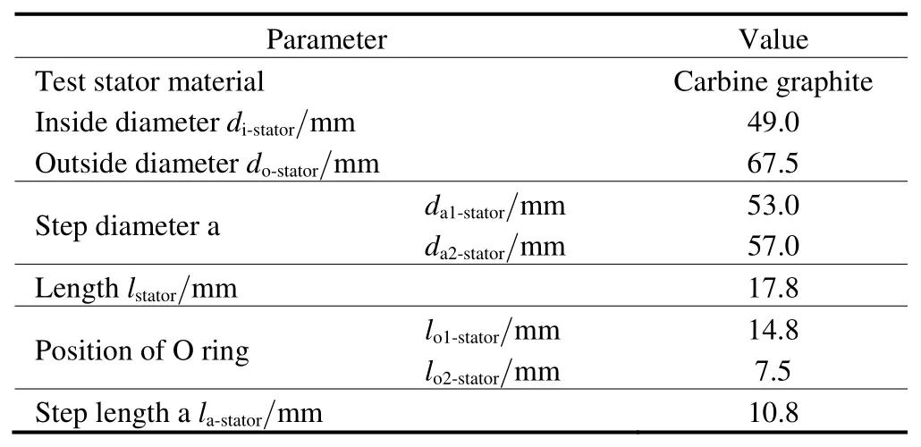
The size chain schematic diagram of the test rings of a S-DGS was shown in Fig.3,and the related parameters of construction and test conditions for testing in high pressure were shown in Table 1,Table 2 and Table 3.The difference between structure a and structure b of the stator is the step diameters a and b,i.e.,da1-statorand da2-statorrespectively,as shown in Table 2.Sizes of lo1-statorand lo2-statorshowed the different positions of O-ring.

Fig.3.Size chain schematic diagram of the test rings

Table 1.Specifications for rotor

Table 2.Specifications for stator

Table 3.Test conditions
3.1 Opening performance
Figs.4 and 5 showed the average film clearance between the two faces and leakage rate of a S-DGS varying with static pressure,poof 0–5 MPa,respectively.The experimental procedure was repeated three times in order to ensure repeatability and reliability of the test results.It could be seen that the experiment results were well in repetition and dependability.
Fig.4 showed that the average film clearance increased with increasing po.The average film clearance increases from 0 to 5.2 μm when poincreases from 0 to 5 MPa.This means that when pois not less than 5 MPa,the static pressure could provide enough opening force to separate the seal faces.When powas higher than 5 MPa,theaverage film clearance showed the same results which means that the seal operated at the stable conditions.
Fig.5 showed that the leakage rate increased with increasing seal pressure po.It was concluded fromFig.4 that the leakage rates followed the trend of clearance in general.When poincreased higher than 0.6 MPa,the leakage rates began to increase,it increased from 0 to 13.89 L/min during poincreased from 0 to 5 MPa.When poincreases from 3.5 MPa to 4 MPa,the leakage rate increased obviously.

Fig.4.Experimental static opening curves of clearance
3.2 Influence of structure parameters
3.2.1 Influence of seal ring size
(1)Surface wear.It was seen from Fig.6 that optical images and profiles of sealing surface for different sizes of stator ring after running 30 s at 500 r/min and 5 MPa,in which the position of secondary O-ring seal was position b.

Fig.5.Experimental static opening curves of leakage
Results showed that seal ring sizes had obvious influence on face wear.The influence degrees of various seal face width on wear surface were different.The width of seal faces decreased gradually from structure a to structure b in order.Analysis on 3D electron microscope and surface roughness tester illustrated that structure b showed more serious face wear than that of structure a.Furthermore,the wearing capacity of structure a(0.041 1 g)was less than that of structure b(0.044 9 g),and the surface roughness of structure a was less than that of structure b(see Table 4).This indicated that face wear could be formed by coning due to pressure deformation of seal ring,the seal face contacted with each other directly because of the lack of sealed gas.So face wear occurred at the high pressure side of seal faces,which satisfied the theoretical prediction.

Table 4.Measured surface roughness distribution for different structures of graphite ring
(2)Sealing performance analysis.Figs.7 and 8 showed the influence of seal ring size on leakage rate and face temperature during start-and-stop test,respectively,in which the position of secondary O-ring seal referred to position b.
Results showed that the leakage rate and face temperature of structure a was less than that of structure b.Thereinto,procedure(a)was the process which the seal face opened by static pressure(it means the rotational speed is zero),the leakage rate and its gap between structure a and structure b increased with increasing pofrom 0 to 6 MPa(see Fig.7).The face temperature remained unchanged(see in Fig.8).The leakage rate and face temperature increased with increasing rotational speed n from 0 to 600 r/min during procedure(b).The difference of leakage rate between structure a and structure b was in the range of 24%–25%,and the difference of temperature between structure a and structure b was around 1.2℃–22.3℃.The procedure(c)and the procedure(d)were corresponding to depressurization and deceleration steps,respectively.The leakage rate reduced in both procedures,while the face temperature increased with reducing n from 600 r/min to 0 except depressurization.When podecreased from 6 MPa to 0,the face temperature would reduce.The whole experiment process,which was from procedure(a)to procedure(d),could be attributed to the fact that the deformation could make the leakage rate and face temperature increase.

Fig.7.Comparison of results of different sizes of ring for face leakage rate during start-stop test
3.2.2 Influence of secondary O-ring seal position
(1)Surface wear.Fig.9 showed the optical images and profiles of sealing surface of structure a of the test stator for different positions of secondary O-ring seal when the seal run at 600 r/min and 6 MPa,the run time t=70 s.
The results showed that face wear rate would be different when the positions of secondary O-ring seal varied.Compared with the effect of seal ring size(see Fig.6),the influence of position of secondary O-ring seal is less.Analysis on 3D electron microscope and surface roughness tester illustrated that the face wear rate of a S-DGS with position a was more obviously than that of a S-DGS with position b.Moreover,the wear rate of a S-DGS with position a(0.046 2 g)is more than that of a S-DGS with position b(0.043 2 g),and the surface roughness of a S-DGS with position a was less than that of a S-DGS with position b(see Table 5).This indicates that a more contact area at the high pressure side of the seal faces occurred on a S-DGS with position a of secondary O-ring seal because of the deformation.Face deformation of a S-DGS with position a was more than that of a S-DGS with position b,which was carried out to clarify the influence rule of position of secondary O-ring seal.

Table 5.Measured surface roughness distribution for different positions of secondary O-ring seal
(2)Sealing performance analysis.Figs.10 and 11 showed the influence of position of secondary O-ring seal on leakage rate and face temperature during start-and-stop test of a S-DGS,respectively,in which the stator with graphite ring referred to structure a.

Fig.10.Comparison of results of different positions of secondary O-ring seal for leakage rate during start-and-stop test
Compared with the effect of seal ring size(see Figs.7 and 8)on leakage rate and face temperature,the influence of position of secondary O-ring seal was less.The same result as these was gotten with the research of surface wear as shown in Fig.9.The leakage rate and face temperature of a S-DGS with position a were more than that of a S-DGS with position b.The influence of secondary O-ring seal position on leakage rate was greater than that on face temperature.The experiment measures were test with equal process of Figs.7 and 8.The gaps of leakage rate and face temperature between position a and position b were less than 5.9% during the procedure(b)test.During the tests of procedure(c)and procedure(d),the gaps of leakage rate or face temperature between position a and position b were also little,especially the gap of temperature was only less than 3%,so these gaps could be ignored.
4 Conclusions
(1)When static sealed pressure was not less than 5 MPa,the pressure can provide enough opening force to separate the seal faces.With sealed pressure increasing,the leakage would increase but face temperature be unchanged.The leakage and temperature increased with increasing speed.The leakage reduced during depressurization and deceleration steps,and the temperature increased with reducing speed except depressurization step,the temperature reduced.
(2)Face wear happened at the high pressure side of seal faces because of face deformation,and the deformation could make the leakage and face temperature increase.These results were compared well with the theoretical predictions.
(3)The seal ring size of a S-DGS had obvious influence on face wear.Face wear,leakage and face temperature of a S-DGS with a smaller cross sectional area of seal ring were less than that of a S-DGS with a bigger one.
(4)Compared with the effect of seal ring size,the influence of secondary O-ring seal position was less,and the differences of leakage or face temperature of a S-DGS between with position a and with position b could be ignored.Compared with a S-DGS with O-ring seal closing to the seal face,a S-DGS with O-ring seal away from the seal face would show greater influence of O-ring seal position on seal performance and face deformation.The influence of position of O-ring seal on leakage was more than the effect for face temperature.
[1]XU Jing,PENG Xudong,BAI Shaoxian,et al.Numerical analysis of gas thermal viscosity effect on performance of a spiral-grooved dry gas seal[J].Journal of Shanghai Jiaotong University,2012,46(5):722–728.(in Chinese)
[2]XU Jing,PENG Xudong,BAI Shaoxian,et al.Both surface micro-scale and thermal viscosity effects on sealing performance of a spiral grooved dry gas seal[J].CIESC Journal,2013,64(9):3291–3300.(in Chinese)
[3]XU Jing,PENG Xudong,BAI Shaoxian,et al.Calculation methods of face torsional deformation and related affecting factors for mechanical seal[J].CIESC Journal,2013,64(10):3686–3693.(in Chinese)
[4]MAYER E.Mechanical seal[M].Beijing:Chemical Industry Press,1981.(in Chinese)
[5]HIFUMI Mitsuo.Study of high efficiency turbocompressor development of high speed and high pressure dry gas seal[J].IHI Engineering Review,2005,2(38):1–5.
[6]BO R.A mixed lubrication model of liquid/gas mechanical face seal[J].Tribology Transactions,1997,40(4):647–658.
[7]BAHETI S K,GKIRK R.Analysis of high pressure liquid seal ring distortion and stability using finite element methods[J].Journal of Tribology,1999,121(3):921–925.
[8]BRUNETIERE N,TOURNERIE B,FRENE J.TEHD lubrication of mechanical face seals in stable tracking mode.Part 1:numerical model and experiments[J].ASME Journal of Tribology,2003,125(3):608–616.
[9]BRUNETIERE N,TOURNERIE B,FRENE J.TEHD lubrication of mechanical face seals in stable tracking mode.Part 2:parametric study[J].ASME Journal of Tribology,2003,125(3):617–627.
[10]BRUNETIERE N,THOMAS S,TOURNERIE B.The parameters influencing high pressure mechanical gas face seal behavior in static operation[J].Tribology Transactions,2009,52(5):643–654.
[11]BRUNETIERE N.An analytical approach of the Thermo-elasto-hydro-dynamic behavior of mechanical face seals operating in mixed lubrication[J].Proc.IMechE.Part J-J Eng.Tribol.,2010,224:1221–1233
[12]LEBECK A O.Principles and design of mechanical face seals[M].Wiley Interscience Publication,John Wiley and Son,1991.
[13]PHILIP J,GUICHELAAR M W,CHAO W O.Experimental verifications of thermal elastic mechanical seal face deflection by local wear measurements[J].Lubrication Engineering,2000,56(1):26–32.
[14]WEN Qingfeng,LIU Ying,HUANG Weifeng,et al.The effect of surface roughness on thermal-elasto-Hydro-dynamic model of contact mechanical seals[J].Science China,2013,56(10):1920–1929.
[15]PENG Xudong,FENG Xiangzhong,HU Danmei,et al.Numerical analysis of deformation of a non-contacting gas lubricated seal[J].Tribology,2004,24(6):536–540.(in Chinese)
[16]PENG Xudong,LIU Wei,BAI Shaoxian,et al.Effects analysis of thermo-elastic deformation on the performance of hydrostatic mechanical seals in reactor coolant pumps[J].Journal of Mechanical Engineering,2010,46(23):146–153.(in Chinese)
[17]GU YONGQUAN.Mechanical face seal[M].Shandong:Press of Petroleum University,1994.(in Chinese)
[18]THOMAS S,BRUNETIERE N,TOURNERIE B.Thermo-elastohydro-dynamic behavior of mechanical gas face seals operating at high pressure[J].Journal of Tribology,2007,129(3):841–850.
[19]GREEN I,GEORGE W.A transient dynamic analysis of mechanical seals including asperity contact and face deformation[J].Tribology Transactions,2002,45(3):284–293.
杂志排行
Chinese Journal of Mechanical Engineering的其它文章
- Wear Analysis of Disc Cutters of Full Face Rock Tunnel Boring Machine
- Dimensional Description of On-line Wear Debris Images for Wear Characterization
- Temperature Distribution and Scuffing of Tapered Roller Bearing
- Case-Based Reasoning(CBR)Model for Ultra-Fast Cooling in Plate Mill
- Development of Evaluation Technique of GMAW Welding Quality Based on Statistical Analysis
- Modified Pressure Loss Model for T-junctions of Engine Exhaust Manifold
