Mesoplasticity Approach to Studies of the Cutting Mechanism in Ultra-precision Machining
2014-02-07LEEWBRongbinWANGHaoTOSuetCHEUNGChiFaiandCHANChangYuen
LEE WB Rongbin*,WANG Hao,TO Suet,CHEUNG Chi Fai,and CHAN Chang Yuen
Partner State Key Laboratory of Ultra-precision Machining Technology,The Hong Kong Polytechnic University,Hong Kong S.A.R.,China
1 Introduction*
In ultra-precision machining,a very sharp single crystal diamond tool with a tool radius of 0.01–0.05 μm and possessing high hardness and wear resistance is employed.Cutting is performed on a computer numerical controlled machine with high stiffness,enabling the fabrication of high quality optical surfaces of almost any shape,with the surface finish in the nanometre level and the form accuracy in the sub-micrometre level.These optical components have been used as indispensable elements for information transmission products,photonics and telecommunication products,computer hardware,etc.With the advances in computer and control technologies,there has been a drastic improvement in the design and manufacture of ultra-precision computer numerical controlled machines over the past few decades.However,there has not been a parallel development in understanding of the physical mechanism of the micro and nano-cutting process,and the optimisation of the machining process still heavily relies on experience and trial and error,especially when new cutting materials are being used.Ultra-precision machining differs from conventional machining in that it deals with complex elastic and plastic deformation in the machining surface,such as material swelling,which is found to be pronounced when the depth cut is small.Workpieces for ultra-precision machining are usually either polycrystalline(such as copper based or aluminium based alloys)or single crystals(such as infra-red materials or KDP crystals).They are seldom homogeneous,and possess strong anisotropic properties.These affect the cutting force variation and chip formation and hence the surface finish of the cut.The depth of cut is of the order of microns and is much less than the average grain size of the workpiece to be cut.Macro-metal cutting theories are based on continuum mechanics and are thus unable to take into account the micro-features of these materials,such as the crystallographic orientations.In this paper,the background of mesoplasticity is introduced,and some of the achievements in using the mesoplasticity approach for the prediction of the shear angle in chip formation,the variation of micro-cutting forces and the high frequency tool-tip vibration in ultra-precision machining are presented.
2 Mesoplasticity
The physical phenomenon of plastic deformation is approached by various length scales,and the corresponding academic disciplines are shown in Fig.1,which also gives rise to mesoplasticity studies that require an integrated approach to micro-,meso-and macro-mechanics[1–2].In recent decades,various theories of the micro-cutting mechanisms in ultra-precision machining have been developed,with contributions from the analytic and numerical modelling methods as summarised in Table 1.These include slip-line field modelling,molecular dynamics simulation(MDS),quasi-continuum(QC)method,mesh-free method,discrete element method(DEM),and finite element method(FEM),etc.Most research into ultra-precision machining focuses on a particular aspect of the technology,and seldom links up the different length scales which all affect the quality of the machined surface at the micro-and nano-level.The theory of ultra-precision machining has been studied from the perspectives of various disciplines,from continuum mechanics,materials science,to computer modelling.However,there have been relatively few studies employing a multi-disciplinary and multi-scale approach.
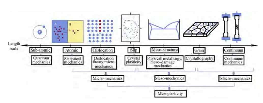
Fig.1.Diagram of the length scale of plasticity investigation
The depth of cut in ultra-precision machining is usually below the average grain size which is in the order of a few micrometres(Fig.2).In other words,the micro-cutting is performed from one single grain to another.Therefore,the crystallographic structure of the workpiece material has a great influence on the quality of the machined surface.In conventional machining,it is unnecessary to consider the fluctuation of the cutting force resulting from the changes in grain orientations.In our contribution to the research field,mesoplasticity[1–2]has been used to analyse the fluctuations of the shear angles and hence the micro-cutting force in ultra-precision single point diamond turning.The existing theories for machining require cutting trials to determine the chip geometry before the shear angle can be calculated.Furthermore,most of these existing metal cutting theories make the assumption that the isotropic work material is a homogeneous continuum,and the material anisotropy is not considered in the analysis.
The mesoplasticity method is the first to employ an integrated approach for the multi-scale investigation of the mechanics in the micro-,meso-and macro-scale.A summary of the modelling procedure from LEE,et al[1]is as follows.
(1)Selection of an appropriate length scale to best describe the phenomenon of interest.
(2)Highlighting the essential microstructures for consideration with the background material treated as a continuum.
(3)Employing the constitutive models obtained in the prior finer length scales for the background material as a continuum.
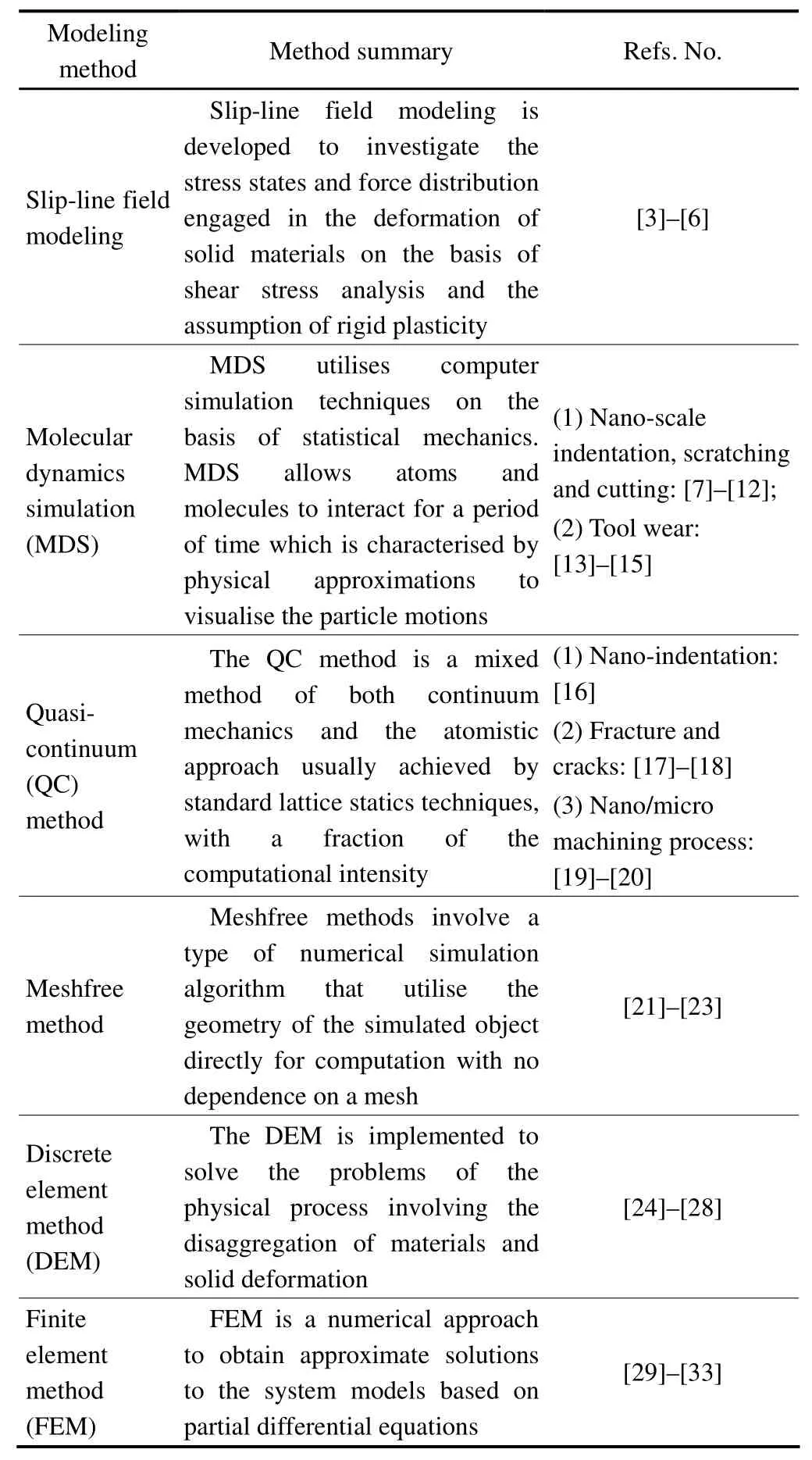
Table 1.Modeling methods for machining processes
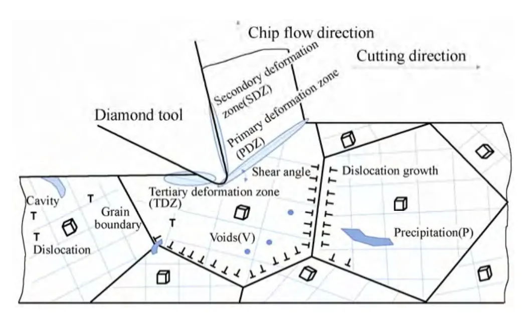
Fig.2.Schematic of micro-cutting with imperfections in work material
Usually,useful knowledge of material behaviour will only be gained at the correct scale of observation.A good example of the plasticity problem is the shear banding phenomenon in large deformations.The first optical observation of shear bands in an optical microscope was reported twelve years before the birth of the dislocation theory of crystals,which tried to understand the atomic processes involved in the slip in crystals.Many properties are structure sensitive.Traditionally,many descriptions of mechanical behaviour are based on the average properties of the material which is treated as a continuum.This is opposite to the practice in solid state physics where the macroscopic properties are derived from the statistical properties of the micro-components of the systems being studied.The major framework of continuum mechanics was developed at a time when modern techniques for the characterisation of materials structures were not available.With the advances in computing technology and image analysis,quantitative techniques for describing and quantifying many aspects of material structures at the grain level(such as spatial distribution and orientation)have become commonplace.These provide the opportunity for solving problems built on a continuum-based microstructure formulation.The following is the outcome of using such an approach in tackling machining phenomena encountered in metal cutting at the micro-and nano-scale of accuracy and observation.
3 Micro-cutting Mechanism
3.1 Limitation of classical cutting theory
In conventional machining,a large shear angle indicates a high efficiency of material removal,low cutting force and good surface finish[34–38].The magnitude of the shear angle is related to the depth of cut,the chip thickness,the rake angle of the cutting tool,and the friction between the tool and workpiece interface[34–35].In the classical metal cutting theories,prior prediction of the shear angle is impossible as the chip thickness can be measured only after a machining cut has been made.Although many attempts have been made since the fifties to modify the Merchant type of equations,they have met with partial success only[36–38].With the wide application of single point diamond turning(SPDT),interest in studying the shear angle in microcutting started to emerge.SATO,et al[39],attempted to correlate the shear angle and shear stress based on Hill’s criteria,but were not successful.Since then,much research work on shear angle analysis in micro-cutting,based on the conventional shear angle analysis,has been carried out,but has met with only partial success[40].More recently,an empirical model to analyse the cutting force based on the observation of chip formation was proposed by ARCONA,et al[41].However,some important material properties,such as hardness and Young’s modulus,have to be obtained before a prediction can be made.In addition,the effect of crystallographic orientation on the cutting force variation[42]and shear angle variation[43]were not taken into an account in deriving these shear angle equations.
3.2 Prediction of shear angle and micro-cutting force
Shear angle is one of the essential factors in a machining process that influences the micro-cutting forces and machined surface finish of the workpiece.The shear angle in the meantime determines the chip morphology and steady-state cutting condition with the formation of regularly spaced shear bands(RSSB)which is a significant characteristic of steady and high-efficiency cutting conditions[44].
A variety of classical theories for shear angle calculation have been developed to reveal the correlation between the magnitude of the shear angle,the geometry of cutting tools and the friction angles.Among these models,the well-known ones are Merchant’s theory and the slip-line field theory.However,these models could not predict the magnitude of the shear angle which could only be measured from the depth of cut and the thickness of the chip obtained from cutting experiments.
SATO,et al[39],employed the continuum yield theory in their analysis on shear stress and shear angle,taking into consideration the effect of material anisotropy.Nevertheless,their attempt has been regarded as unsuccessful as their obtained shear angle value was in the reverse phase to shear stress.According to our systematic experiments[45–53],a definite relationship is identified in ultra-precision diamond turning between the crystallographic texture or orientation(Fig.3)and the machined surface roughness(Fig.4).On the basis of crystal plasticity theory,the value of the Taylor factor can be utilised to infer the value of the shear angle for a particular crystallographic orientation.The Taylor factor(M)can be readily derived from the maximum work principle[54]to relate the effect of strain in the workpiece coordinates(dεw)and the total dislocation shear(dΓ)as M=dΓ/dεw.The shear angle is therefore predicted,based on the load instability criteria,to appear where the minimum effective Taylor factor is determined with the smallest number of dislocation slip systems[55–56].The microplasticity model for the prediction of shear angle has been proposed by LEE,et al[57].With regard to the work-piece coordinate system,the symmetric tensor for the strain in a shear band(εw)is expressed by Eq.(1),where dτ and φ are the shear strain and shear angle,respectively.Eq.(2)transforms the stain tensor from a work-piece coordinate system into the crystallographic axes where the slip system is based.The virtual work for deforming a single crystal is assessed by Eq.(3),where dΓis the total dislocation shear strain and τcdenotes the critical resolved shear stress on the active slip systems.The criteria for shear band formation is thus given by Eq.(4),where the term(1/M)(dM/d εw)is called the texture softening factor.The prediction of the cutting force variation is further accomplished by incorporating the calculated results of the shear angle into Eq.(5),which is derived from macro-mechanics cutting theory,such as the classical one from Merchant[58],where A is the area of the undeformed chip thickness,d and b are the depth and width of cut,τ is the shear stress,α and β are rake angle and friction angle,respectively:
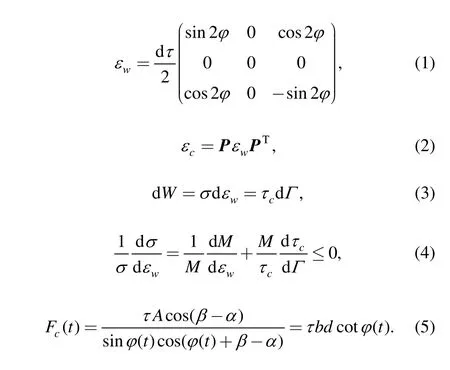
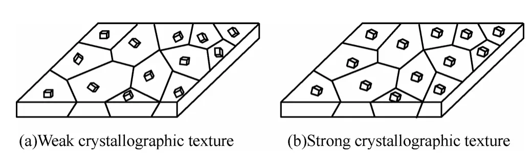
Fig.3.Schematic diagram of work materials showing

Fig.4.Effect of crystallographic orientation on surface roughness
The shear angles acquired from the cutting of two crystals with different crystallographic orientations are shown in Fig.5.The rake angle of the diamond tool used in the experiment is zero.There is a good agreement between the experimental data and the theoretical prediction results(see Table 2).Therefore,the shear angle thus calculated can be an input into various continuum mechanics models to predict the corresponding variation in the cutting forces[57,59–61].For instance,in a turning operation,the crystallographic orientation of the workpiece material alters with the cutting direction which results in the periodic fluctuations in the measured cutting forces.Such fluctuations are found to depend on the crystallographic symmetry of the workpiece materials and the machining parameters of the spindle speed.A force sensor is used to measure the cutting force variation which is further analysed by a power spectrometer.
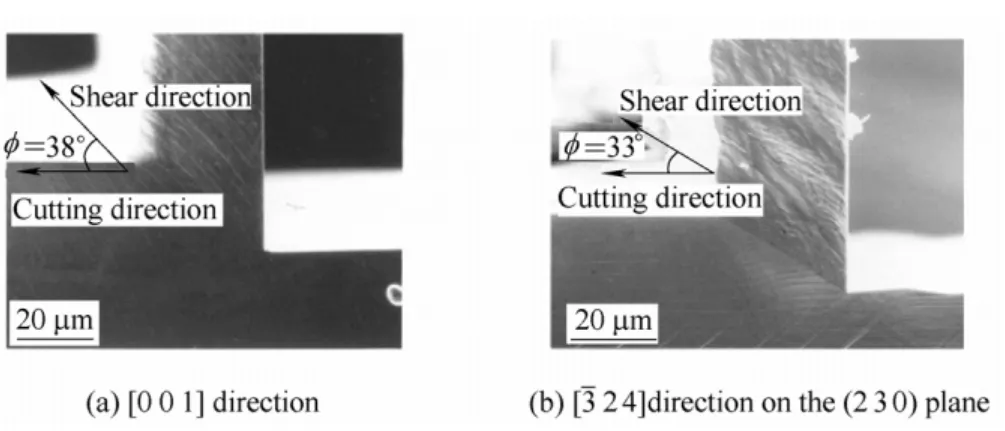
Fig.5.SEM images of shear zone formation of cutting copper single crystals
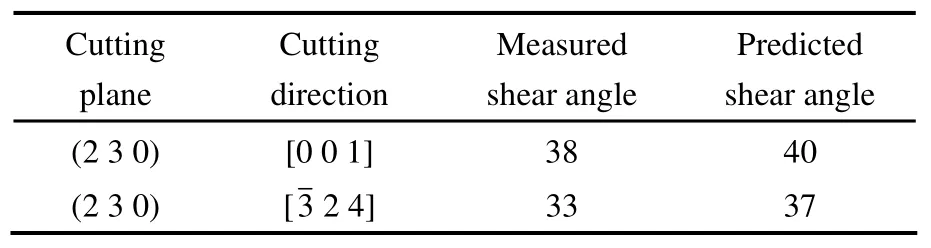
Table 2.The measured and predicted shear angle for different cutting directions on the(230)plane
The predicted values of shear angles with the corresponding variation of the cutting force in the diamond turning of aluminium single crystals on the(0 0 1)plane are shown in Fig.6.As shown in Fig.7,the plots of the predicted and the measured spectra for the variation of cutting forces in diamond turning on the(0 0 1)plane are also found to agree reasonably well.From Table 3,it can be deduced that there exists a fundamental cyclic frequency in the variation of the cutting forces for each turning revolution of the workpiece.The cyclic frequency has been determined to be four,for(0 0 1)crystals.The predicted spectrum and the measured spectrum both possess a dominant frequency component(f2)which nearly coincides with the fundamental cyclic frequency for(0 0 1)crystals.This demonstrates that the microplasticity model is useful in explaining the variation of the micro-cutting force with changes in crystallographic orientations during a revolution of cutting.As confirmed by the cutting tests,the main features and patterns of the cutting forces are well predicted by themodel.
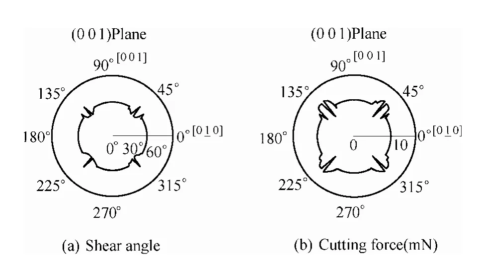
Fig.6.Predicted variation of shear angle and cutting forces in diamond turning(0 0 1)aluminium single crystal
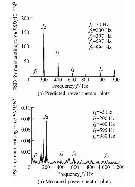
Fig.7.A comparison of the predicted and measured power spectral plots for the cutting forces in diamond turning of(001)aluminium single crystal
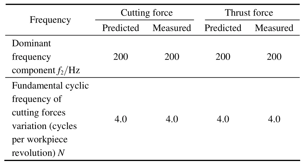
Table 3.Measured and predicted shear angle for different cutting directions on the(230)plane
3.3 Crystal plasticity finite element modeling(CPFEM)for micro-cutting forces
The crystal plasticity constitutive relation is integrated into the simulation of the micro-machining process to identify the influence of the crystallographic orientation on the variation of the cutting force[62].The constitutive law adopts the model devised by ZHANG,et al[63]with some modifications.To deal with the finite deformation problem in micro-cutting,the rigid body rotation factor is considered with Eq.(6),in the calculation of the updated Cauchy stress(σ):
With the small elastic deformation assumption,the increment of the elastic logarithmic strain()is expressed by Eq.(7),whereis the 4th order tensor of the elastic modulus:

The total strain increment follows the additive decomposition of Eq.(8):
where the plastic strain component(Δεp)of a single crystal is further expanded into Eq.(9),where m(α)*and s(α)*are the updated crystal orientations and Δγ(α)is the shear strain increment of the slip system α:
The strain hardening of slip system is characterised by the power law in Eq.(10):
where g(α),γ0and m are the critical resolved shear stress,reference slipping rate and the rate sensitivity factor of slip,respectively.The strain hardening effect of the slip system β on the slip system α is defined by Eqs.(11)and(12),where h0,qαβ,a and τsare slip hardening parameters:
To simulate orthogonal micro-cutting,the CPFE model is implemented by programming the crystal plasticity constitutive equations with the user’s subroutine Hypela2 of MSC.Marc.The global remeshing technique is employed to deal with the problem of severe mesh distortion induced by the large deformation in material removal.The simulation results of the cutting force,thrust force and the equivalent Cauchy stress in orthogonal micro-cutting of copper single crystals are shown in Fig.8[62],which validate the developed CPFE model for the study of the anisotropy effect in micro-cutting of a single crystal material.
3.4 Size effect in ultra-precision machining
In ultra-precision machining,indentation by the tool-edge of the cutting tool occurs.This gives rise to complex elastic and plastic deformations in the machining surface,such as material swelling,which is found to be pronounced when the depth of cut is small[64].In conventional machining,the cutting force will increase with depth of cut.However,when the depth of cut is reduced from 400 nm and below in ultra-precision machining,the cutting force starts to increase.A similar phenomenon is observed in micro-or non-indentation when the depth of indentation is becoming smaller.This can be simulated by the micro-scratching experiment for FCC single crystals.The size effect in micro-scratching of an FCC single crystal is studied by measuring the ratio of the thrust force to the projected area of contact between the cutting tool and the work-piece by varying the depth of scratch at the submicron scale[65].The modelling of the machining process requires hierarchical treatment from dislocation dynamics to crystal plasticity.The numerical procedures and implementation details for conventional crystal plasticity used by ZHANG,et al[63]have been adopted,and the strain gradient effect has been incorporated into the crystal plasticity by LEE,et al[65].
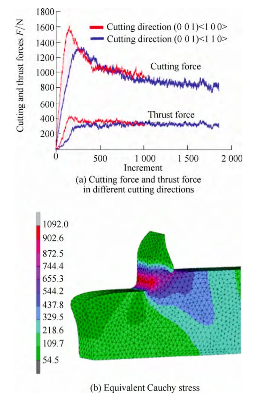
Fig.8.Simulation results of cutting force and thrust force in different cutting directions and the equivalent Cauchy stress in the(0 0 1)<1 0 0>cutting,with the developed CPFEM model
The findings on the analysis of micro-scratching on a single crystal copper are shown below.The dimensions of the workpiece are 10 μm×10 μm×5 µm for a sharp conical indenter.The three dimensional FE mesh is shown in Fig.9(a)with 11 375 nodes and 9408 elements.The region right below the indenter head of the specimen is represented by finer meshes to obtain a precise calculation of the deformation in that region.The half-angle of the conical indenter is 72°.The crystal coordinate system coincides with that of the sample.Whereas all the other surfaces free of constraints,the bottom surface of the work-piece is fixed.An indentation in the crystallographic direction of[0 0 1]is performed at point A with indentation depths 100 nm and 400 nm,respectively(see Fig.9(b)).This is then followed by scratching to point B along the crystallographic direction of[1 0 0]while keeping the respective depth of indentation unchanged.To characterise the size effect in microscratching,the ratio of the thrust force to the areas obtained by the projection of the total contact areas to a plane normal to the scratching direction is defined here as an appropriate measure,which is expediently termed the thrusting hardness.
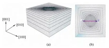
Fig.9.FE mesh for the scratching simulation for a sharp conical indenter
Fig.10 presents the distribution of the displacement components in the direction of[0 0 1],corresponding,respectively,to Fig.10(a)scratching depth 100 nm and Fig.10(b)scratching depth 400 nm.Fig.11 shows the calculated thrusting hardness at different scratching depths.It is seen that an increase of thrusting hardness,approximately 500 MPa,is obtained with a decrease of scratching depth from 400 nm to 100 nm.This demonstrates an appreciable size effect in the microscratching of crystalline materials.At a scratching depth of 100 nm,the thrusting hardness fluctuates up and down with tool travel since the density of the mesh is not sufficiently high for the calculation.This results in a considerable jump in the hardness in consecutive steps.However,such variation can be reduced by the use of finer mesh sizes but this would greatly increase the computing time.
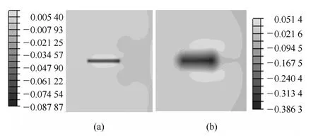
Fig.10.Distribution of displacement components in the direction of[0 0 1]
It is noted that the present constitutive model has been calibrated by a direct comparison of the modeling results of LEE,et al[65]to the experimental findings of MCELHANEY[66],who made accurate measurements of hardness versus depth of indentation in copper from 2000 nm down to 100 nm.A good agreement was found.In addition,the phenomena of material swelling associated with nano-indentation,which were found to have a large effect on the measurement of hardness,are often observed in single point diamond turning and ultra-precision machining[67].Material swelling generally refers to the elastic-plastic response of a work piece when the cutting tool is removed,the effect of which is clearly demonstrated in the simulation results.The MSG-CP model is promising for analysing scale-dependent problems in ultra-precision machining.
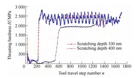
Fig.11.Thrusting hardness corresponding to the scratchingdepth of 100 nm and 400 nm
Material swelling causes a tool mark that deviates from the theoretical tool profile imprinted on the machined surface.Such effect can neither be explained by the tool feed,machine vibration or the tool nose waviness alone,and is found to be more pronounced with decreasing depths of cut.There is a strong correlation between material swelling and surface roughness.This research can lead to a better understanding of the size effect,the underlying mechanism of material swelling and its characteristics.
4 Regularly Spaced Shear Bands and High-frequency Tool-tip Vibration
Surface finish in machining is highly dependent on the vibrations and dynamic interactions between the tool and the workpiece,which include the cutting parameters and material properties of the part to be cut.Although ultra-precision machining is relatively free of machine chatter,localised instabilities will take place repeatedly,accompanied with the formation of serrated chips.The steady serrated chip formation is essential to good surface finish on the machined surface because the building up of residual stress due to the incompatibility between the imposed macroscopic strain and the microscopic homogeneous strain must be removed from time to time.Thus,the serration must be regular in terms of punctuality(just-in-time)and must be of high frequency(sufficiency).The regularly spaced shear band(RSSB)is a significant characteristic of steady and high-efficiency cutting conditions,and is therefore a desirable chip type,accompanied with a minimised primary deformation zone.Shear band formation has long been studied in heavily cold-rolled non-ferrous metals,but less in the ultraprecision machining process in which the common work piece materials are copper and aluminium alloys.Critical questions are raised about how the shear band is triggered in the course of machining and how the imposed strain is accommodated in the primary deformation zone.The study of chip morphology versus shear angle has received extensive attention since Merchant proposed his classic equations over six decades ago.Though Merchant’s model and its derivatives can well fit with the scenarios of conventional machining,material anisotropy due to crystallographic texture,which is of particular importance in ultra-precision machining,has not been adequately reflected in the macroscopic models.Our research addresses a key theoretical problem in the mechanism of ultra-precision machining,i.e.,shear band formation and chip morphology and its effect on surface finish.The effect of high-frequency tool-tip vibration(HFTTV),and the conditions for the formation of RSSB have been evaluated by integrating different constitutive equations into the finite element simulation.
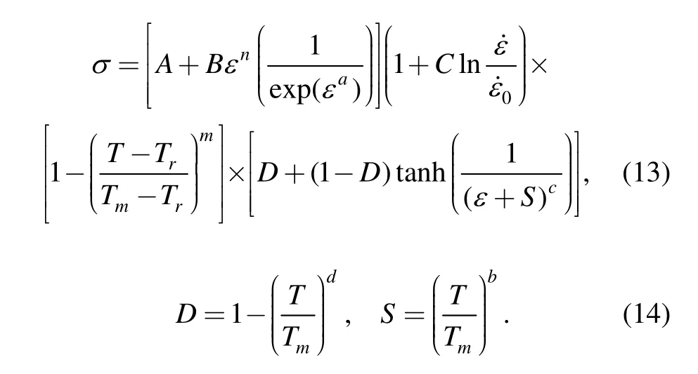
In the theoretical investigation of the micro-cutting process and chip formation,elastic strain induced shear bands are studied with finite element modeling[68].The TANH constitutive equation[22]is employed in the FE model to characterise the effect of work softening with respect to shear band formation in the primary deformation zone.The TANH constitutive model is expressed by Eqs.(13)and(14),where A,B,C,n and m are the Johnson-Cook constants,a,b,c and d are the material constants,σ,ε and T denote the equivalent flow stress,plastic strain and temperature,respectively:
Based on the simulation results shown in Fig.12[44],it is concluded that for a constant strain rate,the formation of RSSB is assisted by the elastic strain concentration,and shear bands are initiated at the free edge of the chip.The RSSB,once initiated,will then propagate from the free edge of the chip towards the tool tip.No RSSB will be formed if the shear is initiated at the tool tip because it will trigger a load drop almost instantly which renders the shear angle relatively unpredictable under constant strain rate cutting.In addition,this fictitious shear band cannot be very linear because the strain field will keep re-aligning in response to the propagation of such a shear band.The accumulation of elastic strain energy leads to the abrupt load drop caused by the periodic shear band formation at high frequency.This results in the two stages of engagement and disengagement of the tool with the chip during the cutting process,which has been further identified in the dynamic behaviour of machine tools as high-frequency tool-tip vibration(HFTTV)[69–70].The power spectrum density(PSD)analysis on the cutting force signals reveals the characteristic twin peaks with regard to HFTTV in the high frequency range with small amplitude(Fig.13[44,70]).The influence of HFTTV on the machined surface has been identified in a zero-feed turning experiment as shown in Fig.14[44].
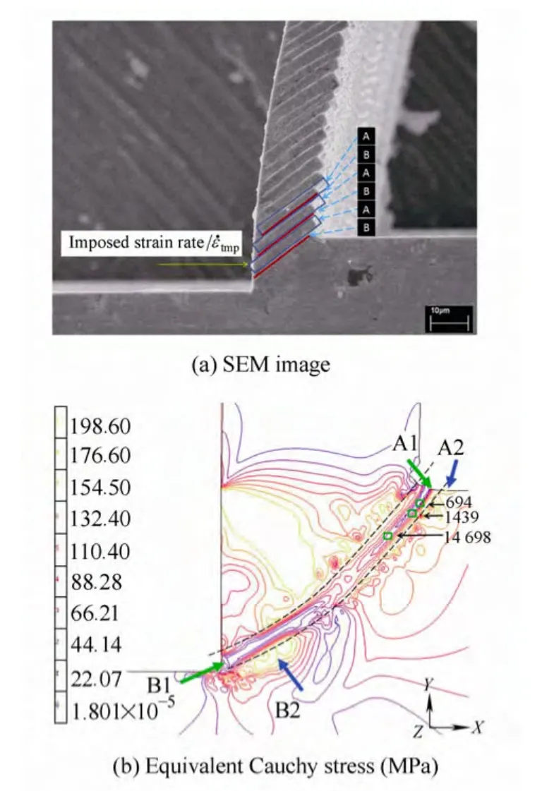
Fig.12.SEM image of regularly spaced shear bands and equivalent Cauchy stress in the primary deformation zone simulated by finite element modeling of the micro-cutting process
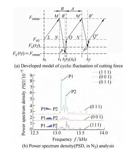
Fig.13.Developed model of cyclic fluctuation of cutting force and power spectrum density(PSD,in N2)analysis of acquired cutting force in facing of aluminium single crystals
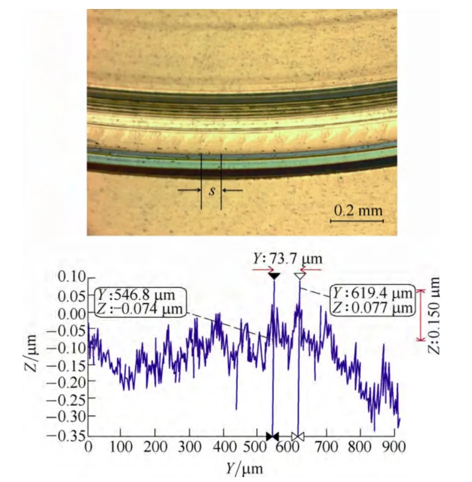
Fig.14.Notch-like marks in zero-feed cutting on Al6061-T6 work-piece and the measured peak-to-peak distance in 2D profile by Wyko NT8000
5 Conclusions
This paper presents the background of mesoplasticity and its applications in the investigation of the micro-cutting mechanism in ultra-precision machining.To achieve a good surface finish,steady state cutting conditions,which favour the formation of regularly spaced shear bands in the formation of the chip process,need to be established.This requires a better understanding of the factors causing the variation of the shear angle and hence the fluctuation of the micro-cutting force and the high-frequency tool-tip vibration in the machining process,which cannot be adequately explained by macro-cutting theories alone.The proposed mesoplasticity model has been successfully applied to explain the effect of material induced vibration and the relationship between the cutting force and the surface quality.This paper paves the way forward for the establishment of a multi-scale study model(from the micro-meso-and macro-scales)in the simulation of the three-dimensional nano-surface topology in ultra-precision diamond turning.
Acknowledgement
The authors wish to acknowledge the Research Committee of The Hong Kong Polytechnic University and the Innovation Technology Commission of The Hong Kong SAR Government for their financial support of the Hong Kong Partner State Key Laboratory of Ultra-Precision Machining Technology.
[1]LEE W B,YANG W.Methodology and applications of mesoplasticity in manufacturing sciences[J].International Journal of Mechanical Sciences,1993,35(12):1079–1095.
[2]YANG W,LEE W B.Mesoplasticity and its applications[M].Springer-Verlag,1993.
[3]FANG N.Slip-line modeling of machining with a rounded-edge tool—Part I:new model and theory[J].Journal of the Mechanics and Physics of Solids,2003,51:715–742.
[4]FANG N.Slip-line modeling of machining with a rounded-edge tool—Part II:analysis of the size effect and the shear strain-rate[J].Journal of the Mechanics and Physics of Solids,2003,51:743–762.
[5]FANG N,DEWHURST P.Slip-line modeling of built-up edge formation in machining[J].International Journal of Mechanical Sciences,2005,47:1079–1098.
[6]TOROPOV A,KO S-L.Prediction of tool-chip contact length using a new slip-line solution for orthogonal cutting[J].International Journal of Machine Tools &Manufacture,2003,43(12):1209—1215.
[7]TRESOFF J.New empirical model for the structural properties of silicon[J].Physical Review Letters,1986,56(6):632–635.
[8]LIN Z C,HUANG J C.A nano-orthogonal cutting model based on a modified molecular dynamics technique[J].Nanotechnology,2004,15(5):510–519.
[9]FANG F Z,WU H,LIU Y C.Modeling and investigation on machining mechanism of nano-cutting monocrystalline silicon[J].International Journal of Machine Tools &Manufacture,2005,45:1681–1686.
[10]FANG F Z,WU H,ZHOU W,HU X T.A study on mechanism of nano-cutting single crystal silicon[J].Journal of Materials Processing Technology,2007,184(1–3):407–410.
[11]SHIMADA S,IKAWA N,TANAKA H,et al.Feasibility study on ultimate accuracy in microcutting using molecular dynamics simulation[J].Annals of the CIRP,1993,42(1):91–94.
[12]INAMURA T,SHIMADA S,TAKEZAWA M,et al.Brittle/ductile transition phenomena observed in computer simulations of machining defect-free monocrystalline silicon[J].Annals of the CIRP,1997,46(1):31–34.
[13]KOMANDURI R,CHANDRASEKARAN N,RAFF L M.Effect of tool geometry in nanometric cutting:a molecular dynamics simulation approach[J].Wear,1998,219(1):84–97.
[14]KOMANDURI R,CHANDRASEKARAN N,RAFF L M.M.D.simulation of nanometric cutting of single crystal aluminum– effect of crystal orientation and direction of cutting[J].Wear,2000,242(1–2):60–88.
[15]GOEL S,LUO X,REUBEN R L.Wear mechanism of diamond tools against single crystal silicon in single point diamond turning process[J].Tribology International,2013,57:272–281.
[16]TADMOR E B,MILLER R,PHILIPS R,et al.Nanoindentation and incipient plasticity[J].Journal of Materials Research,1999,14(6):2233–2250.
[17]MILLER R,ORTIZ M,PHILIPS R,et al.Quasicontinuum models of fracture and plasticity[J].Engineering Fracture Mechanics,1998,61(3–4):427–444.
[18]MILLER R,TADMOR E B,PHILIPS R,et al.Quasicontinuum simulation of fracture at the atomic scale[J].Modelling and Simulation in Materials Science and Engineering,1998,6(5):607–638.
[19]SUN X,CHEN S,CHENG K,et al.Multiscale simulation on nanometric cutting of single crystal copper[J].Proceedings of the Institution of Mechanical Engineers,Part B:Journal of Engineering Manufacture,2006,220:1217–1222.
[20]PEN H,BAI Q,LIANG Y,et al.Multiscale simulation of nanometric cutting of single crystal copper– effect of different cutting speeds[J].Acta Metallurgica Sinica(English Letters),2009,22(6):440–446.
[21]LIMIDO J,ESPINOSA C,SALAÜN M,et al.SPH method applied to high speed cutting modelling[J].International Journal of Mechanical Sciences,2007,49(7):898–908.
[22]CALAMAZ M,COUPARD D,GIROT F.A new material model for 2D numerical simulation of serrated chip formation when machining titanium alloy Ti-6Al-4V[J].International Journal of Machine Tools &Manufacture,2008,48(3–4):275–288.
[23]CALAMAZ M,LIMIDO J,NOUARI M,et al.Toward a better understanding of tool wear effect through a comparison between experiments and SPH numerical modeling of machining hard materials[J].International Journal of Refractory Metals &Hard Materials,2009,27(3):595–604.
[24]ZHANG B,TOKURA H,YOSHIKAWA M.Study on surface cracking of alumina scratching by single-point diamonds[J].Journal of Materials Science,1988,23:3214–3224.
[25]LEI S,YANG B.Distinct element simulation of ceramic machining:material removal mechanism[J].Transactions of the North American manufacturing Research Institution of SME,2005,33:485–492.
[26]TAN Y,YANG D,SHENG Y.Study of polycrystalline Al2O3 machining cracks using discrete element method[J].International Journal of Machine Tools &Manufacture,2008,48(9):975–982.
[27]TAN Y,YANG D,SHENG Y.Discrete element method(DEM)modeling of fracture and damage in the machining process of polycrystalline SiC[J].Journal of the European Ceramic Society,2009,29(6):1029–1037.
[28]POTYONDY D O,CUNDALL P A.A bonded-particle model for rock[J].International Journal of Rock Mechanics &Mining Science,2004,41(8):1329–1364.
[29]KAKINO Y.Analysis of the mechanism of orthogonal machining by the finite element method[J].Journal of the Japan Society for Precision Engineering,1971,37(7):503.
[30]SHIRAKASHI T,USUI E.Simulation analysis of orthogonal metal cutting process[J].Journal of the Japan Society for Precision Engineering,1976,42:340.
[31]IWATA K,OSAKADA K,TERASAKA Y.Process modeling of orthogonal cutting by the rigid-plastic finite element method[J].ASME Journal of Engineering Materials and Technology,1984,106(2):132–138.
[32]UEDA K,MANABE K.Rigid-plastic FEM analysis of three-dimensional deformation field in chip formation process[J].Annals of the CIRP,1993,42(1):35–38.
[33]LIU K,MELKOTE S N.A strain gradient based finite element model for micro/meso-scale orthogonal cutting process[C]//Proceedings of 2004 Japan-USA Symposium on Flexible Automation,Denver,Colorado(2004).
[34]ERNST H,MERCHANT M E.Chip formation,friction and high quality machined surfaces[J].Surface Treatment of Metals,Am Soc Met,1941,29:299–378.
[35]SHAW M C.Metal cutting principles[M].MIT Press,Cambridge,MA,1954.
[36]OXLEY P L B.Mechanics of machining:an analytical approach to assessing machinability[M].Chichester:Ellis Horwood Limited 1989.
[37]HASTINGS W F,MATHEW P,OXLEY P L B.A machining theory for predicting chip geometry,cutting forces etc.from work material properties and cutting conditions[J].Proceedings of the Royal Society of London Ser.A,Math and Phy Sci,1980,371:569–587.
[38]LEE E H,SHAFFER B W.The theory of plasticity applied to a problem of machining[J].Journal of Applied Mechanics,1951,18:405–413.
[39]SATO M,TAKAO Y,YASUS S,et al.Effect of material and anisotropy upon the cutting mechanism[J].Trans.JIM,1978,19:530.
[40]UEDA N,MATSUO T,HOSHI T.An investigation of some shear angle theories[J].CIRP Annals-Manufacturing Technology,1986,35(1):27–30.
[41]ARCONA C,DOW T A.An empirical tool force model for precision machining[J].Journal of Manufacturing Science and Engineering,1998,120(4):700–707.
[42]MORONUKI N,LIANG Y,FURUKAWA Y.Experiments on the effect of material properties on microcutting processes[J].Precision Engineering,1994,16(2):124–131.
[43]BLACK J T.Shear front-lamella structure in large strain plastic deformation processes[J].Journal of Engineering for Industry,1972,2:307.
[44]WANG H,TO S,CHAN C Y,et al.A study of regularly spaced shear bands and morphology of serrated chip formation in microcutting process[J].Scripta Materialia,2010,63(2):227–230.
[45]CHEUNG C F.Influence of cutting friction on the anisotropy of surface properties in ultra-precision machining of brittle single crystals[J].Scripta Materialia,2003,48(8):1213–1218.
[46]CHEUNG C F,LEE W B.Study of factors affecting the surface quality in ultra-precision diamond turning[J].Materials and Manufacturing Processes,2000,15(4):481–502.
[47]CHEUNG C F,TO S,LEE W B.Anisotropy of surface roughness in diamond turning of brittle single crystals[J].Materials and Manufacturing Processes,2002,17(2):251–267.
[48]TO S,LEE W B,CHAN C Y.A study on ultraprecision diamond turning of aluminium single crystals[J].Journal of Materials Processing Technology,1997,63(1–3):157–162.
[49]TO S,LEE W B,CHAN C Y.Effect of machining velocity on the crystallographic texture in a diamond turned aluminum single crystal[J].Textures and Microstructures,1999,13(4):249–261.
[50]TO S,LEE W B,CHEUNG C F.Orientation changes of substrate materials of Aluminium single crystal in ultra-precision diamond turning[J].Journal of Materials Processing Technology,2003,140(1–3):346–351.
[51]LEE W B,CHEUNG C F,LI J G.Prediction of 3-D surface topography in ultra-precision machining[J].China Mechanical Engineering,Transactions of CMES,2000,11(8):845–848.
[52]LEE W B,CHEUNG C F,TO S.Materials induced vibration in ultra-precision machining[J].Journal of Materials Processing Technology,1999,89–90:318–325.
[53]LEE W B,TO S,CHAN C Y.Deformation band formation in metal cutting[J].Scripta Materials,1999,40(4):439–443.
[54]BISHOP J F W,HILL R.A theory of plastic distortion of a polycrystalline aggregate under combined stresses[J].Philosophical Magazine,1951,42(327):414–427.
[55]LEE W B,CHAN K C.A criterion for the formation of shear band angles in f.c.c.metals[J].Acta Metallurgica et Materialia,1991,39(3):411.
[56]LEE W B,ZHOU M.A theoretical analysis of the effect of crystallographic orientation on chip formation in micromachining[J].International Journal of Machine Tools and Manufacture,1993,33(3):439.
[57]LEE W B,CHEUNG C F,TO S.A microplasticity analysis of micro-cutting force variation in ultra-precision diamond turning[J].Trans.of ASME,Journal of Manufacturing Science and Engineering,2002,124(2):170–177.
[58]MERCHANT M E.Mechanics of the metal cutting process.I.orthogonal cutting and a type 2 chip[J].Journal of Applied Physics,1945,16(5):267–275.
[59]LEE W B,CHEUNG C F.A dynamic surface topography model for the prediction of nano-surface generation in ultra-precision machining[J].International Journal of Mechanical Sciences,2001,43(4):961.
[60]LEE W B,CHEUNG C F,TO S.Friction induced fluctuation of cutting forces in diamond turning of Aluminium single crystals[J].Proceedings of The Institute of Mechanical Engineers,Part B,Journal of Engineering Manufacture,2003,217(B5):615–631.
[61]LEE W B,TO S,SZE Y K,et al.Effect of materials anisotropy on shear angle prediction in metal cutting—a mesoplasticity approach[J].International Journal of Mechanical Sciences,2004,45(10):1739–1749.
[62]CHEN Y P,LEE W B,TO S,WANG H.Finite element modeling of micro-cutting processes from crystal plasticity[J].International Journal of Modern Physics B,2008,22(31–32):5943–5948.
[63]ZHANG K S,WU M S,FENG R.Simulation of micro plasticity-induced deformation in uniaxially strained ceramics by 3-D Voronoi polycrystal modelling[J].International Journal of Plasticity,2005,21(4):801–834.
[64]TO S,CHEUNG C F,LEE W B.Influence of material swellingupon surface roughness in diamond turning of single crystals[J].Materials Science and Technology,2001,17(1):102–108.
[65]LEE W B,CHEN Y P.Simulation of micro-indentation hardness of FCC single crystals by mechanism-based strain gradient crystal plasticity[J].International Journal of Plasticity,2010,26(10):1527–1540.
[66]MCELHANEY K W,VLASSAK J J,NIX W D.Determination of indentation tip geometry and indentation contact area for depth-sensing indentation experiments[J].Journal of Materials Research,1998,13(5):1300–1306.
[67]KONG M C,LEE W B,CHEUNG C F,et al.A study of materials swelling and recovery in single-point diamond turning of ductile materials[J].Journal of Materials Processing Technology,2006,180(1–3):210–215.
[68]WANG H,TO S,CHAN C Y,et al.Elastic strain induced shear bands in the microcutting process[J].International Journal of Machine Tools &Manufacture,2010,50(1):9–18.
[69]WANG H,TO S,CHAN C Y,et al.A theoretical and experimental investigation of the tool-tip vibration and its influence upon surface generation in single-point diamond turning[J].International Journal of Machine Tools &Manufacture,2010,50(3):241–252.
[70]WANG H,TO S,CHAN C Y,et al.Dynamic modelling of shear band formation and tool-tip vibration in ultra-precision diamond turning[J].International Journal of Machine Tools &Manufacture,2011,51(6):512–519.
杂志排行

Chinese Journal of Mechanical Engineering的其它文章
- Web Tension Regulation of Multispan Roll-to-Roll System using Integrated Active Dancer and Load Cells for Printed Electronics Applications
- Interactive Training Model of TRIZ for Mechanical Engineers in China
- Constant Speed Control for Complex Cross-section Welding Using Robot Based on Angle Self-Test
- Annoyance Rate Evaluation Method on Ride Comfort of Vehicle Suspension System
- Optimizing the Qusai-static Folding and Deploying of Thin-Walled Tube Flexure Hinges with Double Slots
- Experimental Study on Occupant’s Thermal Responses under the Non-uniform Conditions in Vehicle Cabin during the Heating Period