FPGA-Based Network Traffic Security: Design and Implementation Using C5.0 Decision Tree Classifier
2013-11-26TarekSalahSobhandMohamedIbrahiemAmer
Tarek Salah Sobh and Mohamed Ibrahiem Amer
1.Introduction
Intrusion detection is still an open area for researchers.Building a network based intrusion detection system(NBIDS) requires abilities to monitor, mange, and process a millions of packets in a very short-time interval[1],[2].These packets have various formats, different hosts with different operating systems and variable lengths of data.This high variance in format, length, and content needs real-time,intelligent, and accurate systems to deal with, at the mean while these systems should be itself secure and reliable.The software, intrusion detection system (IDS), has many drawbacks in the field of NBIDS[1],[2].
Security of software systems is a function in the security of the hosting system.Performance of software systems has many limitations especially when dealing with a high data bursts (lots of data in short time).Software usually fails at very high traffic conditions.Network traffic is a millions of packets passing in and out of the network in very short periods that needs a dedicated, real-time, reliable,highly available, and secure appliance having intrusion detection as its only task.This work focuses on the design and implementation of hardware network based intrusion detection system using field programmable gate array(FPGA) technology as a core to the system[3]–[5].We elaborated the implementation and the use of hardware appliance in network security.The novel FPGA was implemented for packet processing and connection monitor,aiming finally to implement on chip.The proposed implementation provides a new potential, which can further lead to better performances and more reliable security systems to overcome many speed drawbacks.
The rest of the paper is organized as follows.Section 2 gives a background on Media Independent Interface IEEE Standard 802.3 Clause 22.Section 3 explains the proposed model.Section 4 describes the implementation details of the proposed model.Section 5 presents the function of TCP/IP stack and its implementation.Section 6 introduces C5.0 model using SPSS Clementine.Section 7 presents the performance evaluation results of this work while.Section 8 gives an end-to-end delay comparative study between software-based IDS and hardware-based IDS.Finally, the conclusions and future directions are drawn in Section 9.
2.Media Independent Interface IEEE Standard 802.3 Clause 22
Media independent interface (MII) concerns with 100 Mbps fast Ethernet for describing its functions and specifications[6].This clause defines the logical, electrical,and mechanical characteristics for the reconciliation sublayer (RS) and MII between carrier sense multiple access/collision detect (CSMA/CD) media access controllers and various physical layers (PHYs).Fig.1 shows the location of MII relative to the ISO/OSI reference model.
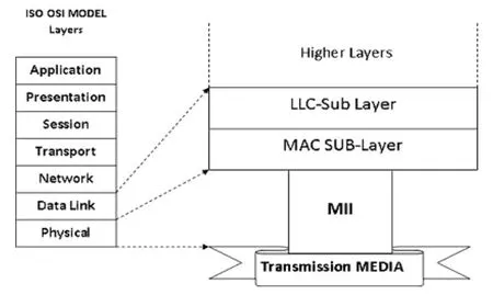
Fig.1.MII relationship to the ISO/OSI reference model.
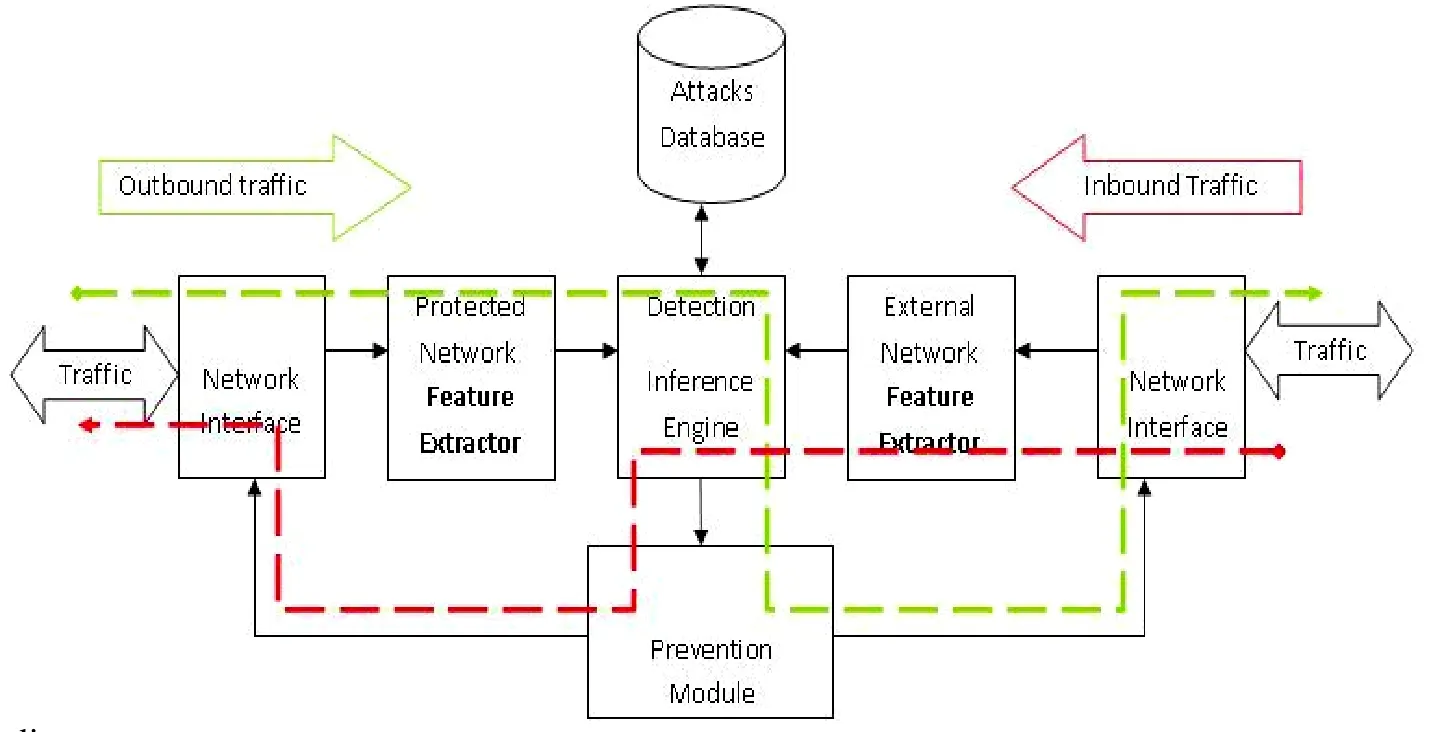
Fig.2.System block diagram.
The purpose of this interface is to provide a simple,inexpensive, and easy-to-implement interconnection between media access control (MAC) sub-layers and PHYs for data transfer at 10 Mb/s and 100 Mb/s, and between station management (STA) and PHY entities supporting data transfer at 10 Mb/s or above.
MII can support two specific data rates, 10 Mb/s and 100 Mb/s.The functionality is identical at both data rates,so are the signal timing relationships.
3.Proposed Model
FPGA hardware is used as a platform to perform high speed packet processing and connection monitor, aiming finally to implement on-chip IDS to be placed at the edge of protected network for providing high performance requirements[7]–[9].
This system must have a parallel processing and intelligence as main basic features.Fig.2 represents the hardware realization of the solutions for implementing the proposed hardware IDS.The proposed system as shown is symmetric around the inference engine from the point of view of the inbound traffic and outbound traffic.The system consists of the following main components.
1) Network interface: its main function is to carry out all the physical layer signaling and protocols that firstly collect the datagram frames from the communication media.This component exists at the face of both interfaces inbound and outbound.
2) Feature extractor: its main function is to extract the layer 2, 3 and four of the collected traffic by the network interface.This component also exists at the face of both inbound and outbound.If the traffic passes through the inbound and outbound extractor simultaneously, there is no difference between their detection results.
3) Attacks database: it carries all patterns and features of attacks.These patterns are used to train the inference engine.This component exists once only for the inference engine.
4) Detection inference engine: this is the intelligent component in the system, receiving and classifying the extracted features by the feature extractor component, and then finally taking decision about this traffic if it is either normal or attack.This decision can further be introduced to prevention module that has the capability of blocking or forwarding the traffic to the other party (inbound or outbound).
5) Prevention module: the prevention module is a gateway of inbound and outbound traffic, forwarding or blocking the traffic.
4.Minimum Hardware Requirements to Implement the Proposed System
The proposed system must meet the following minimum requirements to implement our design.
1) Support MII interface for interfacing with network.
2) Clock with 133 MHz frequency or higher.
3) Memory (RAM) with minimum capacity of 2 Kbit or higher.
4) Two or more MII Ethernet interfaces (one is enough but the board in this case must has at least 12 bit-expansion slots to connect to any other external MII Ethernet interfaces).
Xilinx has released the Spartan-3A/3AN board, which is the most suitable toolkit for implementing our design.Spartan-3A/3AN can meet the minimum hardware requirements of systems[10].
5.Implementation Details of the Proposed Model
Fig.3 represents the implementation of the proposed model using FPGA.The DeMilitarized Zone (DMZ)network in the model represents the trusted network to be protected; the wide area network (WAN) represents the untrusted external network.The DMZ and WAN share inbound and outbound traffic that is generated by DMZ and to be transmitted to WAN is outbound traffic from DMZ point of view and inbound traffic from WAN point of view and vice versus.
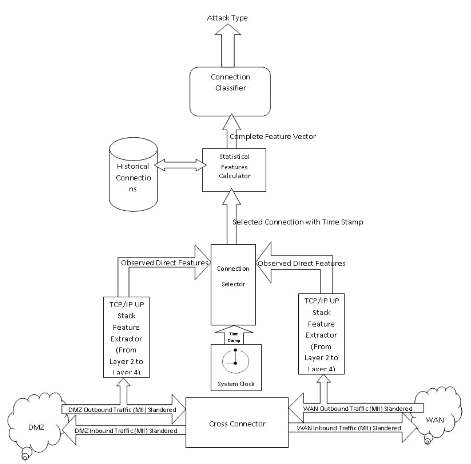
Fig.3.Implementation of proposed system.
5.1 Cross Connector
The functions of the cross connector is to implement MII interface to both DMZ or WAN: pass traffic in both directions without adding significant delay by connecting transmitter of DMZ traffic to receiver of WAN traffic and VSS (vNetwork standard switch); introduce traffic to TCP/IP stack for start processing, and synchronize data flow between two network interfaces (two MII interfaces).Finally, the cross connector, using TCP/IP stack, can be used in the future with prevention module to block or pass traffic by raising error flag signals (MII TX ERR or RX ERR).This process receives the input from both directions of the flows.WAN-RXD is connected to DMZ-TXD and DMZ-RXD is connected to WAN-TXD, also WAN-RX DV to DMZ-TX EN and DMZ-RX DV to WAN-TX EN.The connection between the transmitters of one stream to the receiver of the other has many problems as following.
1) Synchronization problem: each MII interface works independently of the other and has its own asynchronous clock.
2) Propagation delay: the signal transmitted from one card takes a propagation delay from the first interface to the other which is significant with high frequencies (25 MHz).The transmitted data contains five bits.Four bits are reserved to form data and one bit is reserved to validate window and propagation in each line, which makes the data be received at different time.
3) Signal distortion: any bad connection in the path from one interface to the other may cause a distortion to the signal by making flickers at its beginning or end.
Three steps to solve the previous problems are as follows.
1) Sending clock (transmitter clock 25 MHz) sends data from sender to receiver by using coaxial cable and synchronizes the receiver to this clock.
2) Using four locations, the first in first out (FIFO)round buffer is enqueued synchronously to the received clock (transmitter clock) and dequeued by receiver clock with one location distance between Enqueue and Dequeue.Because both clocks are 25 MHz[6], the queue head and tail will keep running after each other without any one to cross the other.Due to synchronous buffer and the distance between Enqueue and Dequeue which use same clocks, it is not possible for the queue to run into congestion as shown in Fig.4.
3) Using a faster clock (133 MHz) at the receiver to latch the data from the transmitter at the middle of transmitted clock, and two fast clocks after the rising edge of the transmitter clock (slow clock), the distortion will be solved by taking a sample in the middle of the data itself.This will solve the propagation delay by waiting two fast clocks after rising edge of transmitter clock (slow clock),give a chance to the different signal to be stable, and ensure all signals received.
Fig.5 describes the function of the fast clock and Fig.6 shows the internal clock of the cross connector.
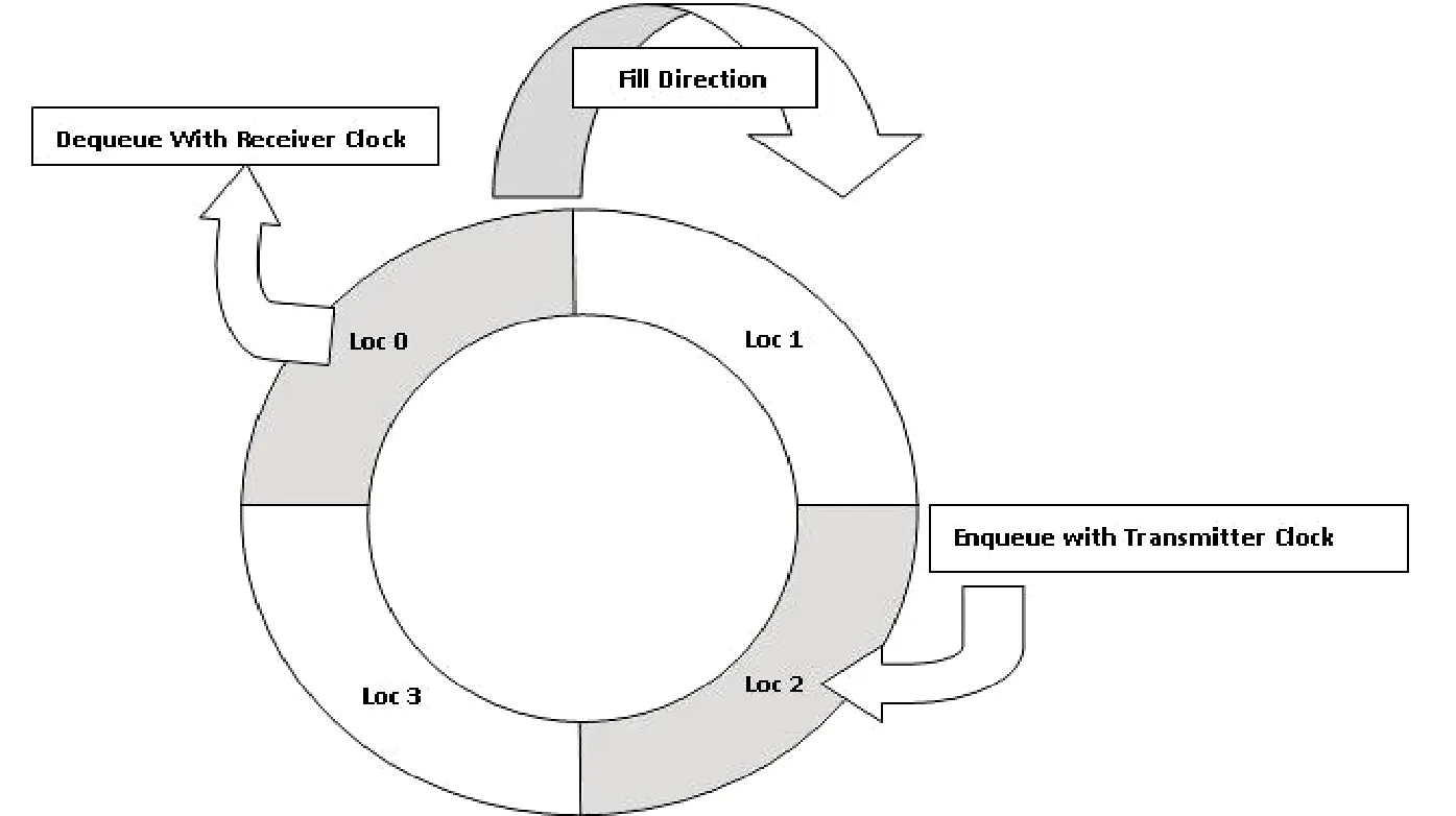
Fig.4.Function of round buffer.
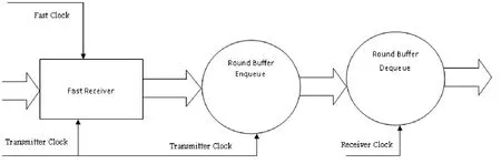
Fig.5.Fast receiver timing diagram.
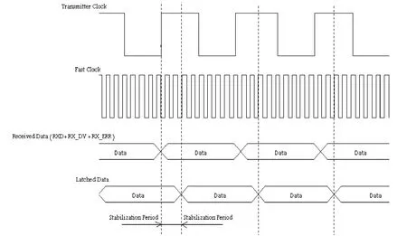
Fig.6.Cross connector internal clock diagram.
5.2 TCP/IP UP STACK
The function of TCP/IP UP STACK is the implementation of TCP/IP stack to remove the header of each layer and extract the layers feature.Fig.7 describes the internal structure of TCP/IP UP stack.
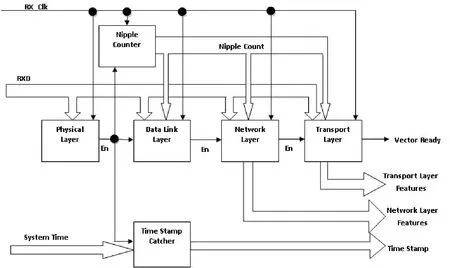
Fig.7.TCP/IP up stack implementation.
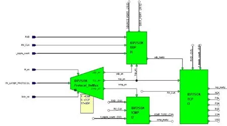
Fig.8.Internal structure of transport layer feature extractor block.
As shown in Fig.7 the TCP/IP up stack consists of six blocks as follows.
A.Physical Layer Block
The function of this block is to remove the PHY header,which is a preamble and start frame delimiter (SFD) to synchronize the received data in RXD with transmitter and determine the starting of the first nipple (4 bits RXD (3 down to 0) as described in MII (2)) of data.After receiving SFD, it sends an enable signal to the nipple counter block to start counting data nipples, to the data link layer block to start removing data link layer headers, and to the time stamp catcher block to catch system time and add it as time stamp to the extracted features, respectively.B.Time Stamp Catcher Block
This block is just a latch register.It latches the input system time and output, then we can get the system time that the frame is received, which is a time stamp of feature vector.
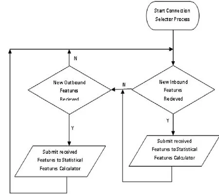
Fig.9.Connection selector process flow chart.
C.Nipple Counter Block
This block starts a counter to count the received nipple from RXD.It is introduced to all layer blocks (data link layer, network layer and transport layer).The count is used to extract the required features in each block.Each feature has a specific location in the incoming stream, so by the help of this counter, each layer block waits the start and the end of the feature and latches it to the output.
D.Layer Blocks (Data Link Layer, Network Layer, and
Transport Layer Blocks)
These layers blocks extract the features from the incoming nipple stream RXD (3 down to 0).These nipples are pushed into a shift register, waiting the count from nipple counter and latching the data from shift register to output to get this feature.The data link layer sends an enable to its next layer (network layer).No feature are extracted from the data link layer, the features are all starting from the network layer.
The transport layer internally contains four blocks in order to extract features from each protocol header according to the transport layer protocol extracted from the network layer.Fig.8 describes the internal structure of the transport layer block.The block starts with protocol demultiplexer and sends an enable to one of the three blocks according to the type of protocols.The corresponding protocol extracts the features and introduces these features to the output.When TCP packet arrives, the enable is sent to both UDP and TCP blocks; the UDP block extracts the first two features and the TCP afterward starts to extract the rest of TCP header features.
5.3 Current Connection Selector
As described in Section 5.1, the system receives and extracts features from inbound traffic and outbound traffic simultaneously that MII runs in a full duplex mode; this may lead to two frames to be received at the same time.In this case, the system must select one among them to add it to the statistical features extractor queue (features preprocessing queue) and then add the other in first-in first-out (FIFO) manner with balancing between the two data sources (inbound and outbound) by current connection selector.Fig.9 describes the flowchart of current connection selector process.
In Fig.9, the system checks for the inbound traffic first.If it finds the new inbound features, the system will submit these features to statistical features calculator, else it checks for outbound features.In both cases of inbound check, true or false, the inbound check is followed by outbound check,and vice versus, thus the IDS swings between the inbound check and the outbound check, giving no priority for any of direction over the other.This prevents IDS from being stuck on short frames in any of two flow directions, leaving the other direction waiting infinitely for his turn.If this balance is not established between both directions, an attack to the IDS system itself may happen.
With short frames on one of IDS traffic, direction attack will stop this direction from functioning and cause all subsequent statistical features to be incorrect because the halted direction frames do not enter the statistical feature queue to be used in calculating these statistical features,causing a deceive to the classifier.
The output of the current connection selector is a vector identified by selector.The IP address and the port number in either of the two networks (internal or external) identify the connection.We have selected internal network to identify the connection by selecting destination IP address and destination port number as the connection identifier in the case of inbound traffic, and selecting source IP address and source port number as the connection identifier in the case of outbound traffic.This is helpful for the statistical features calculator to calculate connection parameters.
5.4 Statistical Features Calculator
This process receives the features from the current connection selector and uses the historical features memory(20X101 synchronous random access memory (RAM)synchronized to the fast clock) to aggregate all past connection as the current target vector to be calculated.The final complete feature vector that is introduced to the classifier in order to classify the feature is extracted as intrusive or normal one.
A.Historical Connections Memory
This memory is 20 record memory in length and 110-bit in width.The 101-bit carries the history of incoming features from connection selector process; this history will be used further in the statistical calculations.
B.Statistics Aggregator
The function of the statistics aggregator is to aggregate the historical connections memory into one record according to the target connection.This aggregator scans all historical connections memory, searching for this connection history, aggregating the stored values, and producing the final feature vector to be submitted to the last step in NBIDS[1],[5].The output of the statistical features calculator consists of two groups of features as described by DARPA[11]–[13].
5.5 Connection Classifier
This process takes the output of statistical features calculator, which is the final feature vector, and uses any classification technique to classify this vector according to pre-learning to this classifier.The output of this process is the attack type.The decision tree is just a one process containing 70 rules generated off-line by SPSS Clementine[13].These 70 rules are just simple IF THEN rules.The IF THEN rules are converted into VHDL codes using C# program and imported into our design to work as the classifier.
6.C5.0 Model Building Using SPSS Clementine
Fig.10 represents the stream built to create the C5.0 classifier rule sets.The detailed description of Fig.10 will be given in Section 6.3.
Fig.11 represents the steps taken to embed C5.0 classifier into the FBGA NBIDS.It describes each process and its input/output.
6.1 Data Preparation and Storage
Many steps are involved in this process in order to prepare data for building a model.
1) Import data from its text representation presented by DARPA into an MS access database.Numbers of imported records are 438331 records.
2) Build a query in MS access database and select the required features for building the required model.
3) Build another query t to remove all duplicate records from selected data.These duplicate data will act as outliers for all other records.
The remaining records after removing redundant data are 76604 records.
Now after these steps, the data is ready to be used to build our required model.
6.2 Building ODBC Connection to Access Database
Open database connectivity (ODBC) is Microsoft’s strategic interface for accessing data in a heterogeneous environment of relational and non-relational database management systems.Based on the call level interface specification of the SQL access group, ODBC provides an open, vendor-neutral way of accessing data stored in a variety of proprietary personal computers, minicomputers,and mainframe databases.
An ODBC connection is build over access database to enable SPSS Clementine to connect/retrieve feature vectors.
6.3 Using Clementine to Generate Model
As shown in Fig.10, Clementine stream contains the following steps to generate model:
1) Use created ODBC connection to link to access database and retrieve these data to the data source node.This node is displayed as Node 1 in Fig.10, entitled“IDS_features_table”.
2) Apply a partition in the path of stream to partition data with 70% to create model and 30% to test model.This node name is called the partition node, Node 2 in Fig.10.
3) Add the C5.0 classifier node, apply 10% noise to the node to simulate real environment, and use 70% partition of data (from its previous node) to build the classifier.This node name is called TRV-SIKO, Node 3 in Fig.10.
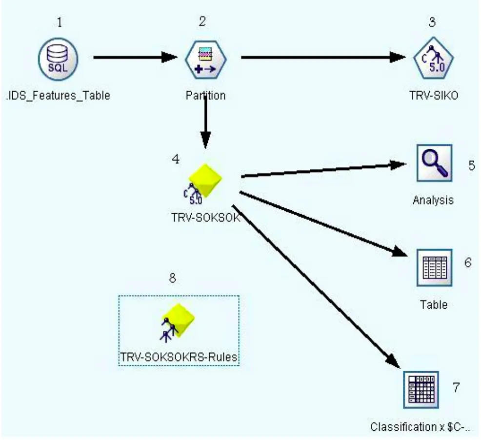
Fig.10.Steps used in generating Clementine model.
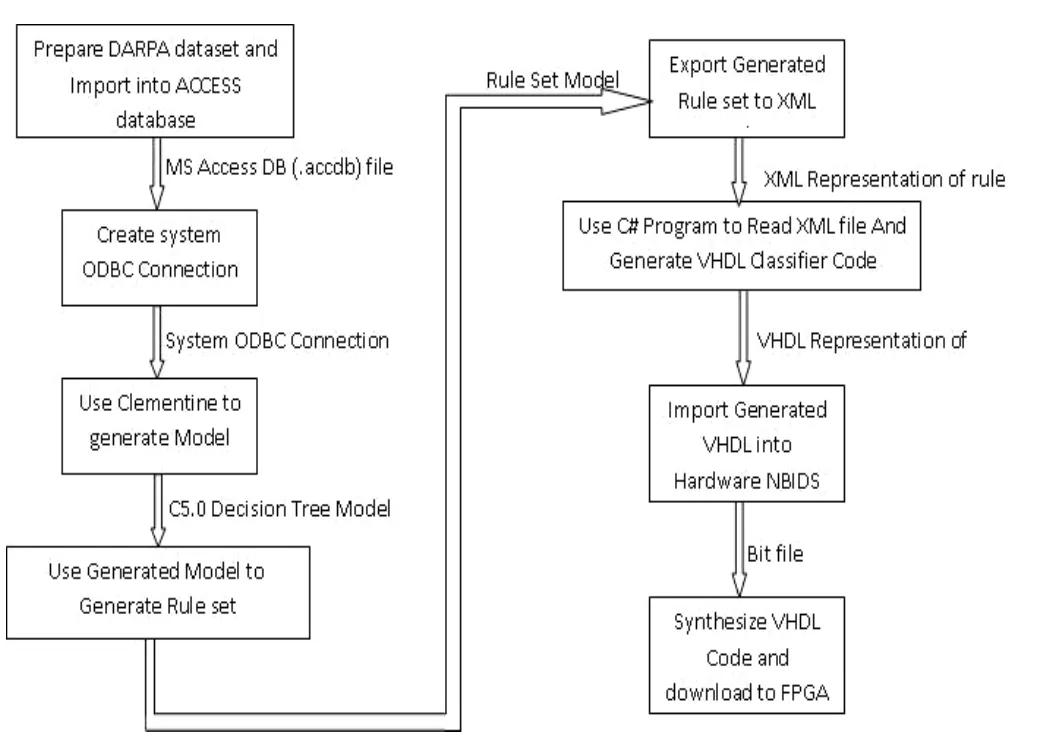
Fig.11.Decision tree generation procedure.
4) Run the TRV-SIKO node to generate the model,which is added and connected to the stream and called TRV-SOKSOK, Node 4 in Fig.10.
5) Add the analysis node, Node 5, to analyze model.
6) Add the table node, Node 6, to see the model results.
7) Add the matrix mode, Node 7, to generate confusion matrix of model.
8) Use the TRV-SOKSOK node to generate the rule set node, Node 8, which is called TRV-SOKSOKRS-RULES.
NOTE: Each node name in the above Clementine stream steps is the user-defined name (dummy name).
6.4 Exporting Generated Model to XML File
Extensible markup language (XML) is a markup language much like HTML.XML was designed to carry data, not to display data.XML is self-descriptive; its tags are not predefined.One must define his own tags.XML is a World Wide Web Consortium (W3C) recommendation.The generated rule set node TRV-SOKSOK in previous section is used to export these rules into XML file.This XML file carries the schema and data of these rules.
6.5 Using Microsoft Visual Studio Dot Net to Build Rule Converter
Microsoft Visual Studio Dot Net (VS.NET) is a platform independent and web based extensible language.VS.NET is used to build a C# program as a code generator for VHDL.The C# program takes the generated XML rule set, parse it and then generate the required VHDL code representing these rules.
6.6 Importing Generated VHDL into Hardware NBIDS
The generated VHDL from previous step is merged by the NBIDS design.The whole system is compiled and built to generate the VHDL modules.The generated VHDL is taken into Xilinx download tool (Xilinx ISE 9.1i).In order to download the VHDL into FPGA chip, the design must pass through the following download steps: 1) user constraints, 2) synthesizing, 3) translating, 4) mapping, 5)placing, 7) routing step, 8) generating programming file and finally, 9) Downloading design[3],[8],[9].
7.Performance Evaluation of the Proposed System
The system as described in Section 5 ran in two clocks.The first clock is the slow lock RX CLK which is the MII sampling clock[6](25 MHz) used to sample data from physical layer, while the other clock is the fast clock (133 MHz), more than five time faster, used in the rest of system blocks.
7.1 End to End Delay (Frame Enter/Exit Delay)
The traffic enters/exits the system through the cross connector (Section 5.1).The cross connector block just delays the traffic.There are three slow clocks (25 MHz) in a pipeline fashion.One clock is used for fast receiver blockwith which the data are sampled after two clocks from the rising edge of slow clock (see Fig.5), one clock is used for round buffer enqueue, and the final clock is used for round buffer selector dequeue (see Section 5.1, Fig.4 and Fig.6).So the end to end delay=3×40 ns=120 ns=0.12 ms.This is the only delay added from our system to the packet while traversing our system.
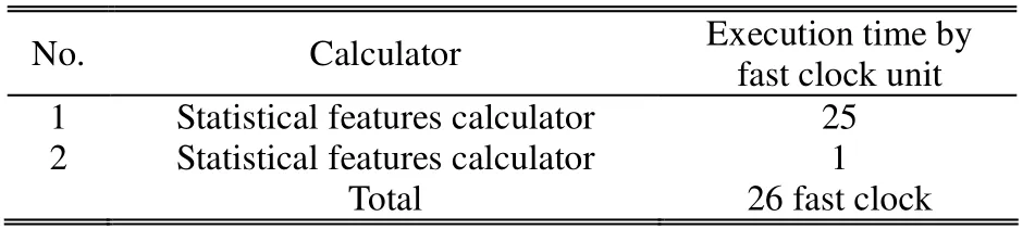
Table 1: Execution time for classification stages
7.2 Processing Time
The processing time is the time taken by our system from receiving the features from TCP/IP up stack (Section 5.2) until a frame is judged if it is normal or attack.All this process is executed by the fast clock (133 MHz) and is divided into three stages as described in Table 1 and as shown in Fig.3.
Table 1 displays total 26 fast clocks.These clocks are used to classify the packet: either a normal packet or an attack packet.
7.3 Proposed System Immunity
Our system is found to be immune against the following attacks.
Denial of service (DoS) attack:
This is an attack to the IDS system itself.Sending a very short packet to the inbound and/or outbound directions of the IDS system will cause IDS to give priority to attacked direction over the other, causing the other direction to be open in front of other attacks.
A.How Did We Face DoS Attacks?
The current connection selector (CCS) balances the processing between two directions by using the flow chart as shown in Fig.9.This case will never happen as we stated in the above sections.
Buffer overflow (BOF) attack:
This attack happens when the system receive a new data to process while it has not finished the current one yet.In this case, the system has to buffer the new data until finishing the current one.Moreover, by increasing traffic,the problem is repeated many times and it is overwhelmed with packets until the buffer is full and the system is crashed.
B.How Did We Face BOF Attacks?
As mentioned previously, the total processing time of the system is 26 fast clocks.The minimum frame length determined by IEEE is 64 byte.According to IEEE specification in MII[6], the data is transmitted/received by 25 MHz clock (slow clock), four bits at a time, i.e., to transmit/receive a Byte needs two clocks.So to transmit the shortest frame, 64×2=128 slow clocks are needed.As 128 slow clocks equal 128×5=640 fast clocks (because we process with the fast clock 133 MHz, five times of the receive clock), the gap between any two shortest frames is 640 fast clocks, while we just need 26 clocks to finish classifying the packet to be normal or attack.That is, we will never encounter buffer overflow conditions because we have more than 600 clocks to wait the next frame.Therefore, no buffer is required to be overwhelmed or overflowed.
7.4 Sensitivity and Specificity Measure for Results
As the interest in intrusion detection has grown, the topic of evaluation of IDS has also received great attention[14]–[17].Sensitivity and specificity are the statistical measures of the performance of a classification test.Classification measures the mappings from the input value X into the classified value Y.
The sensitivity (also called recall rate in some fields)measures the proportion of actual positives, which are correctly identified as: Sensitivity =TP/(TP+FN)[18],[19].
The specificity measures the proportion of negatives,which are correctly identified as: Specificity=TN/(FP+TN)[18],[19].
Positive predictive value or the precision rate is the proportion of positive test classified correctly: Positive predictive value=TP/(TP + FP)[18],[19].
Negative predictive value is the proportion of negative test diagnosed correctly: Negative predictive value=TN/(TN + FN)[18],[19].
Table 2 summarizes the results of measured parameters.
8.Comparative Study between Software & Hardware IDS
Software-based IDS runs directly over transport layer,waiting TCP/IP stack of host and carrying the IDS application to extract features from physical layer, data link layer, network layer, and transport layer[20]–[22].The total delay imposed on a software-based IDS traffic passing are three delays:
1) Receive delay: this delay is wasted in the motion of traffic in the lower layers of TCP/IP stack of host, carrying software-based IDS Down to UP direction.Assuming this delay is only for the first four layers.
2) Processing delay: this is the delay of the processing inside the IDS system itself.
3) Transmit delay: this delay is the same as receive delay except for being wasted in transmitting traffic UP to Down in TCP/IP stack.
The minimum combination for transmit delay or receive delay of running protocols in the first four layers are Ethernet protocol at data link layer, IP protocol at Network layer, and UDP protocol at transport layer.The minimum lengths of these protocols are 14 Byte.The Ethernet header is 20 Byte for IP header without any options or padding while the UDP header is 8 Bytes.Therefore, the minimum delay for any software-based IDS is 42 Bytes (14+20+8=42 Bytes) before starting processing.According to MII, to receive 42 Byte we need 42×2 clocks=84 clocks at each direction (transmit or receive).So thetotal transmit/receive delay is 2×84 =168 clocks (each clock of 25 MHz is 40 ns period).In addition, the minimum transmit delay + receive delay is 168×40=6720 ns=6.72 ms.But our end to end delay is only 0.12 ms.
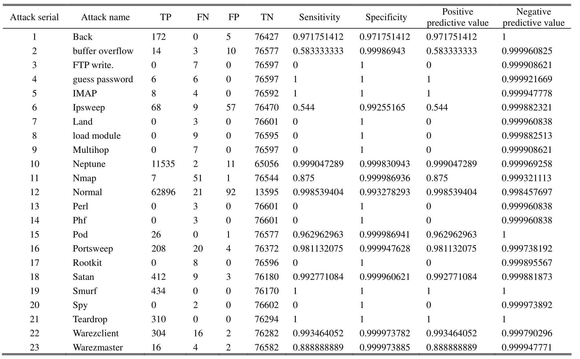
Table 2: Sensitivity and specificity results
9.Conclusion and Future Directions
In this work, a model and its implementation are introduced for building on-chip IDS which satisfies the requirements of the IDS state-of-the-art.The proposed solution is cheep and applicable according to its minimum requirements.We designed the proposed model solution architecture to satisfy the requirements of the IDS.We show that the proposed solution can be optimized for FPGA implementation.In addition, we introduced performance and accuracy measures of the proposed system.
The overall system accuracy is 99.93%.We impose 0.12 ms pipeline delays to network traffic.All features extraction and classification are carried out in parallel.Our system is immune against DoS and BOF attacks.
The presented work is capable of managing any 10100 Mbps Ethernet network.It can serve wireless networks with a little modification of the MAC layer (lower sub-layer of data link layer) to the format of wireless MAC.Using C5.0 gives us a high classification rate and the convenience of implementation by using FPGA.The system can work in a heterogeneous environment independent of operating system or device type as the data source comes as network packets, which are standard.From performance point of view, the software-based IDS has the 56 times (5.72/0.12)delay of our model, making the proposed model to be pioneer in minimum end-to-end delay.
We implemented FPGA-based network traffic security by using C5.0 decision tree classifier.However, there remain many open issues and future challenges as follows:
1) Searching for more recent training datasets is important to replace DARPA, which is a little old one.
2) More features are required to be used in classification process, implementing GMII, XGMII[6]with higher network rates (1 Gbps, 10 Gbps, and 100 Gbps).
3) Implementing wireless Mac layer is important in adding wireless interface.
4) Searching more classification methods, not just decision tree, and implementing them over FPGA.
5) Building more than one classifier in the hardware system and using voting techniques to classify attack.
6) Enhancing immunity of IDS by solving other types of IDS attacks.In addition, implementing IPv6 protocol stack is an important issue.
[1]A.K.Rahuman and G.Athisha, “Reconfigurable hardware architecture for network intrusion detection system,”American Journal of Applied Sciences, vol.9, no.10, pp.1618–1624, 2012.
[2]S.Mühlbach and A.Koch, “NetStage/DPR: A self-reconfiguring platform for active and passive network security operations,” Microprocessors and Microsystems,vol.36, no.8, pp.632–643, 2012.
[3]J.Singaraju and J.A.Chandy, “FPGA based string matching for network processing applications,”Microprocessors and Microsystems, vol.32 no.4, pp.210–222, 2008.
[4]S.Bojani, V.Pejovi, G.Caffarena, V.Milovanovi, C.Carreras, and J.Popovi, “User profiling in FPGA for intrusion detection systems,” Ⅰnformation Assurance and Security Letters, vol.1, no.1, pp.12–17, 2010.
[5]V.P.Sampath, “FPGA based intrusion detection,” World Journal of Science and Technology, vol.1, no.8, pp.100–102, 2011.
[6]802.3-2005: IEEE Standard for Information technology—Telecommunications and Information Exchange between Systems—Local and Metropolitan Area Networks—Specific requirements Part 3: Carrier Sense Multiple Access with Collision Detection (CSMA/CD) Access Method and Physical Layer Specifications, IEEE Computer Society Sponsored by the LAN/MAN Standards Committee, 2005.
[7]A.Das, D.Nguyen, J.Zambreno, G.Memik, and A.Choudhary “An FPGA-based network intrusion detection architecture,” ⅠEEE Trans.on Ⅰnformation Forensics and Security, vol.3, no.1, pp.118–132, 2008.
[8]J.M.B.Serrano and J.H.Palancar, “String alignment pre-detection using unique subsequences for FPGA-based network intrusion detection,” Computer Communications,vol.35, no.6, pp.720–728, 2012.
[9]T.Katashita, Y.Yamaguchi, A.Maeda, and K.Toda,“FPGA-based intrusion detection system for 10 gigabit Ethernet,” ⅠEⅠCE Trans.Ⅰnf.& Syst., vol.E90–D, no.12, pp.1923–1931, 2007.
[10]X.Support, Spartan-3A/3AN Starter Kit Board User Guide,Xilinx, 2007.
[11]C.-M.Chen, Y.-L.Chen, and H.-C.Lin, “An efficient network intrusion detection,” Computer Communications,vol.33, no.4, pp.477–484, 2010.
[12]H.-J.Liao, C.-H.Richard, Y.-C.Lin, and K.-Y.Tung,“Intrusion detection system: a comprehensive review,”Journal of Network and Computer Applications, vol.36, no.1, pp.16–24, 2013.
[13]S.Landau and B.S.Everitt, A Handbook Of Statistical Analyses Using SPSS, London: Chapman and Hall/CRC,2nd ed.2006.
[14]R.P.Lippmann, D.J.Fried, I.Graf, et al., “Evaluating intrusion detection systems: the 1998 DARPA Off-line intrusion detection evaluation,” in Proc.of DARPAⅠnformation Survivability Conf.and Exposition, Los Alamitos, 2000, pp.12–26.
[15]M.Ranum, “Experiences benchmarking intrusion detection systems,” NFR Security White Paper, 2001.
[16]R.Lippmann, J.W.Haines, D.J.Fried, J.Korba, and K.Das, “The 1999 DARPA off-line intrusion detection evaluation,” presented at the Second Int.Workshop on Recent Advances in Intrusion Detection, West Lafayette,1999.
[17]DARPA intrusion detection evaluation.[Online].Available:http://www.ll.mit.edu/mission/communications/cyber/CSTc orpora/ideval/
[18]N.Ye, The Handbook of Data Mining, Mahwah: Lawrence Erlbaum Associates, 2008.
[19]Sensitivity and specificity.[Online].Available:http://en.wikipedia.org/wiki/Sensitivity_and_specificity
[20]M.I.Amer, T.S.Sobh, and G.I.Mohamed, “Using hash table to extract real-time online network traffic features for hardware IDS,” Ⅰnformation Security Journal: A Global Perspective, vol.21, no.1, pp.55–63, 2012.
[21]T.S.Sobh and Y.Aly, “effective and extensive virtual private network,” Journal of Ⅰnformation Security, vol.2, no.1, pp.39–49, 2011.
[22]T.S.Sobh and M.I.Amer, “PGP modification for securing digital envelope mail using COM+ and web services,” Ⅰnt.Journal of Network Security, vol.12, no.3, pp.273–285,2011.
杂志排行

Journal of Electronic Science and Technology的其它文章
- Characterization of Fundamental Logics for the Sub-Threshold Digital Design
- Saudi License Plate Recognition Algorithm Based on Support Vector Machine
- Mobile Web Middleware of NFC Context-Awareness Applications
- Metamaterial Absorbers in Terahertz Band
- Analysis of the Signal of Singing Using the Vibrato Parameter in the Context of Choir Singers
- Broadcasting with Controlled Redundancy and Improved Localization in Wireless Sensor Networks