Object-oriented Modular Model Library for Distillation*
2013-06-07CHENChang陈昌DINGJianwan丁建完andCHENLiping陈立平
CHEN Chang (陈昌), DING Jianwan (丁建完)and CHEN Liping (陈立平)
CAD Center, Huazhong University of Science and Technology, Wuhan 430074, China
Object-oriented Modular Model Library for Distillation*
CHEN Chang (陈昌), DING Jianwan (丁建完)**and CHEN Liping (陈立平)
CAD Center, Huazhong University of Science and Technology, Wuhan 430074, China
For modeling and simulation of distillation process, there are lots of special purpose simulators along with their model libraries, such as Aspen Plus and HYSYS. However, the models in these tools lack of flexibility and are not open to the end-user. Models developed in one tool can not be conveniently used in others because of the barriers among these simulators. In order to solve those problems, a flexible and extensible distillation system model library is constructed in this study, based on the Modelica and Modelica-supported platform MWorks, by the object-oriented technology and level progressive modeling strategy. It supports the reuse of knowledge on different granularities: physical phenomenon, unit model and system model. It is also an interface-friendly, accurate, fast PC-based and easily reusable simulation tool, which enables end-user to customize and extend the framework to add new functionality or adapt the simulation behavior as required. It also allows new models to be composed programmatically or graphically to form more complex models by invoking the existing components. A conventional air distillation column model is built and calculated using the library, and the results agree well with that simulated in Aspen Plus.
distillation system, object-oriented, Modelica/MWorks, level progressive, model reuse
1 INTRODUCTION
Distillation is a method for separating components based on differences in their volatilities in a boiling liquid mixture. It is widely used in petroleum refining, chemical and metallurgical industries and so on. Up to present, a number of special purpose simulators (proprietary simulation tools, such as Aspen Plus, HYSYS, PROⅡ) along with their comprehensive model libraries can be used for modeling and simulation of distillation system. Based on the simulation results with Aspen Plus, Wang and Yao [1] built a model of thermally coupled distillation using artificial neural network algorithm and the model was optimized using genetic algorithm. Yang et al. [2] utilized Aspen Plus to do multiplicity analysis in reactive distillation column for synthesis of ethylene glycol and ethyl tert-butyl ether. Yang et al. [3] simulated a 1,3-butadiene production process with DMF extractive distillation by Aspen Plus. Xu et al. [4] explored three different control methods with HYSYS for a stripping batch distillation column.
In most of these simulators, distillation system is commonly described as a black box, about which users just know how to use but do not know the details. Thus it is difficult to modify an existing model and introduce a new one in these simulators. In another word, the models lack of flexibility and are not open to the end-user. Moreover, the models developed in one tool cannot be easily used in another because of different model descriptions, translation, data organization etc. in these simulators. Although considerable engineering knowledge has been accumulated in various kinds of tools, it is difficult to be shared with each other. Namely it is difficult to reuse and expand the knowledge of models crossing different platforms. The consequence is that huge amounts of work are repeated again and again just because of the barrier between different simulation platforms.
There are also some general simulation platforms, such as Matlab/Simulink, which could be used to model and simulate the distillation process. For example, Khowinij et al. [5] utilized Matlab to simulate dynamic compartmental models of nitrogen purification column. In most of these platforms, the model is usually expressed in an explicit state-space form and iterative process of model solution has to be given if the explicit expression could not be found. For example, it is scarcely possible to express the phase equilibrium equation in an explicit expression because of its strong nonlinearity, so the computational order in the operations during the simulation must be considered by the modeler. Consequently, the topology of the system gets lost and any future extension and reuse of the mode is tedious and error-prone.
Fortunately, among the research in modeling and simulation in the last dozen years, two concepts are closely related to these problems: object oriented modeling language and non-causal modeling. Modelica [6-8], developed in an international effort, is such a physical system modeling language. A major goal of its design is to promote the exchange and the reuse of models between different simulator packages and to introduce a new standard in that way. It supports encapsulation, composition and inheritance facilitating model development and update. Elementary models of physical elements are defined in the declarative expression by their constitutive physical principles, and their interface with the outer world is described by physical connectors without any implied causality, rather than by writing assignments relating inputs to outputs. This makes the description of physical systemsmuch more flexible and natural than that with causal or block-oriented modeling languages, or by directly writing simulation code using procedural languages such as C or FORTRAN. Complex models can then be built by connecting elementary models through their ports. The ports are non-causal, so any connection that is physically meaningful is allowed without restrictions.
The Modelica language includes graphical annotations, which allow to use graphical user interfaces (such as the one provided by the tool MWorks [9, 10]) to select components from a library, drag them into a diagram, connect them, and set their parameters, thus making the process of model development highly intuitive for end users. In order to minimize the development time, Modelica allows the definition and reuse of intermediate elements, common to more models of the same component. The key feature to extensive model reusability and flexibility is given by the extensive exploitation of two Modelica constructs: extend and redeclare, and their associated keywords are partial and replaceable. The partial/extends binomial permits the extension of partial (i.e., partial-complete) models into complete, fully detailed models.
In this article, a distillation model library is built based on the novel multidisciplinary physical modeling language Modelica and the Modelica-supported tool MWorks to provide a framework of distillation system model library with the object oriented technology, level progressive strategy and equation-based model description.
2 STRUCTURING IDEA OF LIBRARY
2.1 Object-oriented modeling and level progressive strategy
Traditionally, physical system model development follows the top-down design approach, which applies the method of functional decomposition to establish the model structure. This method has been successfully applied in many physical engineering domains, but it fails to reflect the real world. Thus many attempts have been made to tackle this problem by applying object-oriented technology.
The library of distillation system is designed as an object-oriented work, which is a set of classes that embodies an abstract design for solution to a family of related problems [11]. The set of classes define “partialcomplete” application that captures the common characteristic of object structures and functionality. Specific functionality in new applications is realized by inheriting from, or composing with, framework components. In this paper, a new object-oriented modeling language Modelica and a Modelica-supported tool MWorks are used to develop the model library, which can be later used to assemble system-level distillation system models.
During the simulation, the mathematical model of system is mapped to collections of interacting objects, rather than decomposed into segments of different functions that can implement certain algorithms. Each object mimics the behavioral and structural characteristic of a physical or conceptual entity models. And it represents an instance of a software class, while the classes are united into a hierarchy via inheritance relationships [11]. For example, the partial model BaseMediawithPR is used to generate different vapor-liquid equilibrium (VLE) media models using the Peng-Robinson equation of state for distillation, but it extends from the more general partial model BaseMedia. If a new media model is to be introduced, it can be easily instantiated from the existing class BaseMediawithPR.
According to the modeling idea mentioned above, the distillation system is decomposed into the process units according to the physical reality (such as the feed tray of distillation column) and further the process units are decomposed into the basic physical phenomenon, such as conservation of mass or of energy, phase equilibrium, etc., as the left branch showed in Fig. 1. Afterwards, models of basic physical phenomenon, unit and system are built level by level using language Modelica and tool MWorks, as the right branch in Fig. 1. As a result, the models of different level, from basic physical phenomenon models, over physical unit modes, to system models, could be reused flexibly in the process of constructing a new model. Thus the professional engineering knowledge can be solidified, propagated and reused in varied granularity.
2.2 Model library for distillation
Following the level progressive modeling strategy mentioned above and considering the maximum reuse of codes in the library, the distillation system could be divided into several sub-systems. Each subsystem consists of various components that are created through inheriting and expanding the basic physical phenomenon models. Fig. 2 presents the architecture of the library and the relationships between different model levels. The library consists of five parts.
(1) Partial components: it is a package of physical components of distillation such as OneInTwoOut, which will be presented in Section 3.3. These components are the basic blocks for building distillation system.
(2) Interfaces: the connectors among the components are defined.
(3) Medium package: it is a package consisting of the media models that are used to compute the VLE. It is a very significant core package, which accounts for about 50% of all codes in the library, and it is the most complicated sub-library in the distillation library. A lot of text will be used to describe it in Section 3.2.
(4) Unit package: it is a package including all the unit models for the library.
(5) Demos: some typical examples of distillation system are given.
The library provides a flexible and extensible environment that can be used to compose new distillation models graphically or programmatically, to examineand edit the existing models, and to simulate and display execution results. It also provides port-compatible software components, with which users can combine to form complex distillation models according to the application.
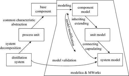
Figure 1 System decompose and modeling with Modelica and Mworks

Figure 2 Structure of model library for distillation
3 COMMON MODEL
3.1 Interface
A special-purpose class connector as an interface defines the variables of the model shared with other models, without implied causality, rather than by writing assignments relating inputs to outputs. In this way the connections can be, besides inheritance concepts, considered as one of the key features of object oriented modeling, enabling effective reuse of model. There are three types of built-in variables: potential variable, flow variable, and stream variable declared with no prefix, prefixes flow and stream.
The potential and flow variables follow the generalized Kirchhoff law. A stream variable describes a quantity carried by a flow variable, i.e., a purely convective transport phenomenon. The value of the stream variable is the specific property (such as mass fraction and specific enthalpy) inside the component close to the boundary, assuming that the matter flows out of the component into the connection point [12]. For example, the connector FluidPort for fluid flow in distillation system has four variables as follows: pressure p, molar flow mdot, specific enthalpy h, and molar fraction x.connectorFluidPort
SI.AbsolutePressure p;
flowSI.MolarFlowRate m_flow;// "positive is flowing from outside into the component "
streamSI.SpecificEnthalpy h;
streamSI.MolarFraction X;
endconnector;

Figure 3 Connection of four componentsC1, C2, C3, C4—connector
Figure 3 shows the connection of four components with the connector FluidPort. The connection point is treated as an infinitely small control volume. All the pressures in each connector must be equalized while the sum of all the molar flows should be zero:

During the model translation, Eqs. (1) and (2), originated from the connector definitions, are automatically generated and added to the other equations of the model. The connection equations with stream variables are generated in a model when using the built-in operator inStream() or actualStream() based on the balance of amount of substance and the physical quantity represented by stream variables [13].
Besides the FluidPort mentioned above, different connector models are available in the library, such as thermo connector. In this paper several connector combinations are introduced and classified into the library. For example, there are two input and two output ports in the common tray model, one input port for the gas phase while the other for liquid phase and so are the output ports. The four ports interface model named FourPortsPartial model are introduced.
3.2 Medium
The media model is one of the most important cores of this library. Its computational efficiency and accuracy have a strong impact on the simulation time and accuracy of the whole process system model. The prediction methods of vapor-liquid equilibrium in these tools are mostly fugacity coefficient method and fugacity-activity coefficient method. With the former method the fugacity coefficients of vapor phase and liquid phase are calculated from the thermodynamic equation of state. The fugacity coefficient of vapor is from the thermodynamic equation of state (EoS) and the activity coefficient from excess function with the later method. The users of these tools just know how to use vapor-liquid equilibrium model but do not know the mechanism of modeling in these tools.
At present, there are lots of media models for pure substance and mixture in the Modelica Standard Library (MSL) Media [14], but there is no media model for vapor-liquid equilibrium. In this paper, a package named MediaForSapera, which contains physical property calculation with the two-parameter EoS method for vapor-liquid equilibrium, is built based on Modelica in MWorks. The models in this package are based on generic concepts, which allow the introduction of new working media for distillation by modification of a new model parameters and addition of particular EoS. The media package consists of following parts.
(1) PartialModel: consists of the partial media models that contain the common variables, constants, parameters and model structure. At present there is a base partial model and four partial models with two-parameter cubic EoS in the package.
(2) FluidData: consists of records contain the basic physicochemical constants, such as molecular weight and critical temperature, and experimental regression coefficients of pure component of the mixture, such as coefficients of polynomial for specific enthalpy calculation.
(3) Examples: consists of some mixture models for vapor-liquid equilibrium, such as air model made up of nitrogen, oxygen and argon, and simple air model composed of nitrogen and oxygen.
3.2.1Methods of VLE based on two-parameter EoS
Vapor-liquid equilibrium is a condition where a liquid and its vapor are in equilibrium with each other, a condition or state where the rate of evaporation equals the rate of condensation on the molecular level. It can be described by fugacity equality of two phases as follows


The fugacity coefficient method has good thermodynamic consistency and does not need the fugacity of standard state when it is calculated. Its results agree with the experimental measurements very well for a range of mixture except strong polar molecules and electrolyte systems, so it is widely applied to the prediction of vapor-liquid equilibrium of mixture. The two-parameter cubic EoS is used in this paper to model VLE of mixture.
The thermodynamic state equation was proposed a long time ago, which was used in practice for the first time by Van der Waals in 1873 and then had a rapid development in the next one hundred years [15]. The EoS has been widely used in VLE calculation for large range of mixtures, even including strong polarmolecules, during the latest decades. The two-parameter EoS, such as Redlich-Kwong (RK) equation [16], Soave-Redlich-Kwong (SRK) equation [17], Peng-Robinson (PR) equation [18] and Harmens equation [19], has characteristic of a small number of parameter, simple expressions, easily-solving and exact results, so it has been developed very well and applied more widely than other EoS.
At present, four kinds of two-parameter cubic EoS are introduced to model the VLE of mixture in the library. They are RK, SRK, PR and Harmens, and they could be expressed in a unified form:

where p is the pressure of the medium (Pa); T is the temperature of the medium (K); v is the molar volume, (m3·mol−1); R is the universal gas constant (8.314 J·mol−1·K−1); a(T) and b are the parameters of EoS, which are computed by mixing rule of mixture; m and n are constants in different EoS.
The fugacity coefficient and specific enthalpy of mixture are important properties for distillation process simulation. They are computed as follows


When Eq. (5) is applied to a mixture, parameters a(T) and b should be computed by some mixing rules that could be found in reference [20]. For a(T) and b in RK, SRK and PR EoS, the Reid mixing rule is used usually.

where amand bmmean the parameters of EoS for mixture, ai, biand ajare the parameters of components i and j, and kijis binary interaction coefficient between component i and component j, which can be obtained from experiment. The mixing rule for Harmens EoS is different from that for the other three EoS, and it can be consulted in reference [19].
3.2.2Implementation

Figure 4 Sketch of modeling strategy of media model for distillation
There are large numbers of mixtures in distillation processes and so are the medium property prediction methods and the mixing rules of components in mixture. In order to allow the introduction of new working media for distillation by modifying the minimum set ofparameters and adding the minimum set of equations, a structuralized and hierarchical modeling strategy is used for modeling of media model package for distillation, as shown in Fig. 4. The package has three levels: base level, method level and instantiation level.
The base level model is a partial model named BaseMedia, from which all the media models for distillation are extended. It consists of some common parts that can be shared by all models with the method of two-parameter cubic EoS. More details are listed as follows.
(1) Medium constants: media name, names and number of chemical substances, critical properties, etc.
(2) FluidData structure: definition of record type FluidConstants used for storing physicochemical constants of pure substances as follows.
recordFluidConstants
extendsModelica.Icons.Record;
Stringname "Name of ideal gas";
SI.MolarMassmolarMass;
SI.TemperaturecriticalTemperature;
SI.AbsolutePressurecriticalPressure;
SI.MolarVolumecriticalMolarVolume;
RealacentricFactor " acentric factor";
CompressibilityFactorcriticalcompressibility;
Real[5] bh "coefficient of idea media SpecificEnthalpy";endFluidConstants;
Physicochemical constants of all components used in VLE mixture have to comply with this data structure. When a new substance is introduced, the constants are assigned in the order of the sequence of FluidConstants.
(3) ThermodynamicState: a minimum set of variables of state used for function call.
(4) BasePropertiesRecord: common variables shared by all media model with all EoS, such as pressure, specific enthalpy of vapor and liquid phase, and compressibility factor.
(5) BaseProperties: a partial model consisting of common behavior of all media model with all EoS.
(6) Type definition: such as Type compressibility factor=Real(final quantity=“compressibility”, min=0, max=1).
The method level model is extended from the base level model BaseMedia by adding some special variables and the description according to different two-parameter cubic EoS. For instance, the PR EoS has the expression for the fugacity coefficient in vapor phase as follows

redeclare replaceable partial model extendsBaseProperties
…
equation
…
Log(FugacityCoefficientV) = b .* (zV - 1) / bV_Mix .-log((zV - BV_Mix)) - AV_Mix / BV_Mix / (2 *sqrt(2)) * (exmav / aV_Mix .- b / bV_Mix) * (log(((zV + 2.414 * BV_Mix) / (zV - 0.414 * BV_Mix))));
…
endBaseProperties;
Finally the instantiation level models are constructed by extending the method level models and adding the components and the mixing rule of mixture. For example, the air model for distillation is built by defining the medium name, component names and appointing the fluid data of nitrogen, oxygen and argon and the binary interaction coefficient of components as follows.
As discussed above, the reason for introducing the structuralized and hierarchical modeling strategy is that we intent to separate the component information of mixture and the mixing rules from VLE prediction method. The same VLE prediction method can be applied to different mixtures by changing the component information of mixture and mixing rule. Users just need to know the physicochemical constants of componentsand the mixing rule when they introduce a new model. For example, a simple air medium model with PR method, composed of nitrogen and oxygen, is built using the modeling strategy mentioned above. Fig. 5 shows vapor nitrogen concentration vs. liquid nitrogen concentration when the air is in the state of VLE at the pressure of 5.8×10⁵Pa. The maximum error and average error of vapor nitrogen concentration is 1.23% and 0.87%, respectively, between the calculation and experiment. As a conclusion, the results of calculation are acceptable and the model is reasonable.

Figure 5 Comparison of calcula5tion result with experimental data of VLE of air(p=5.8×10 Pa)
3.3 Partial model
Partial model is a kind of semi-complete component, which abstracts the common character shared by a group of operation unit models that have some common properties and behavior or the same structure. It is a basic section of the unit-model sub-library. For example, the condenser, reboiler and throttle valve that could be considered as models include three FluidPorts (one for inlet and two for outlets) as presented in Section 3.1. They have the common properties and behavior as follows.
(1) Mass conservation

where minmeans the mole flow rate of inlet, mout1and mout2are the mole flow rates of two outlets.
(2) Energy conservation

where Hinmeans the enthalpy of inflow, Hout1and Hout2the enthalpy of two outflows, and Q the heat duty of the operation unit.
(3) Mass fraction conservation

where xi,inmeans the mole fraction of inflow, xi,out1and xi,out2are the mole fractions of two outflows.
(4) Vapor-liquid phase equilibrium (computed by medium model)
Thus a partial model OneInTwoOut is built to describe the properties and physical behavior shared by these three unit models and other similar models as follows:
packageN2O2ArWithPR
extendsPartialModel.BaseMediaWithPR (
mediumName="Air for separation",
substanceNames={"O2","Ar","N2"},…);
redeclare model extendsBaseProperties
equation
PureFluidConstants = {FluidData.O2, FluidData.Ar, FluidData.N2};
kij = {{0,0.01396,-0.01238}, {0.01396,0,-0.004.071}, {-0.01238,-0.004.0713,0}};
endBaseProperties;
endN2O2ArWithPR;
partial modelOneInTwoOut
replaceable packageMedium = BaseMedia;
//the needed medium package could be chosen when the model is instantiated
Medium.BaseProperties medium; // medium definition
FluidPort_a In;
FluidPort_b Lout;
FluidPort_b Vout; // port definition: one inlet, two outlets
Medium.HeatFlowRate Q;
equation
In.m_flow+Vout.m_flow+Lout.m_flow = 0; //mass balance
In.m_flow.*In.X+Vout.m_flow.*Vout.X+Lout.m_flow.*Lout.X = zeros(Medium.nXi); // mass fraction balance
In.m_flow*In.h+Vout.m_flow*Vout.h+Lout.m_flow*Lout.h +Q = 0; // energy balance
medium.Xi = Lout.X;
medium.Yi = Vout.X;
medium.p = Lout.p; // the supplementary condition of media model
…
endOneInTwoOut;
At the beginning of the codes mentioned above, the prefix ‘partial’ means that model OneInTwoOut is semi-complete. When a higher level model such as condenser is to be introduced, OneInTwoOut will be inherited and expanded, so the embedded engineering knowledge could be reused on physical behavioral level but not only on model level. In the “equation” region, the behavior described in Eqs. (11-13) is coded in non-causal expression. When the model is to be simulated, MWorks will give the calculation sequence automatically.
4 AN EXAMPLE OF OPERA TIONAL U NIT MODEL: CONDENSER-REBOILER
In this section, a conventional component of distillation system condenser-reboiler is taken as an example to illustrate how to use the model library to build a complete unit model.
As shown in Fig. 6, a condenser-reboiler could be decomposed into three parts: the first one is condenser, which condenses entering vapor to liquid phase partially or completely by transferring the heat to other component, with a wall between condenser and reboiler; the second one is reboiler and its function is opposite to condenser; the third one is the wall between the condenser and reboiler, through which the heat is transferred from the side with higher temperature to that with lower temperature, i.e. from the condenser to the reboiler.
The condenser and reboiler could be expanded from the partial model OneInTwoOut mentioned in Section 3.3. Take the condenser model for example, besides the information included in OneInTwoOut, a heat port and some specialized properties should be added and the model condenser will be completed finally. Herein, variable Q in Eq. (12) equals to the heat flow rate in the heat port. The following codes show how to build a complete condenser model through inheritance and expansion.

Figure 6 Decomposition of condenser-reboiler
modelCondenser
extendsBase.OneInTwoOut;// extend from model OneInTwoOut
Realliquefiedrate;
ParameterAbsolutePressure p;
HeatPort hport; // heat port definition
equation
Q = hport.Q_flow;
medium.T = hp.T;
Lout.p = p;
…
end
The reboiler model could be built with the same method and procedure. The thermal conductor could be found in the Modelica Standard Library (MSL). Based on the object oriented technology, a complete condenser-rebolier model is constructed through combining condenser model, reboiler model and thermal conductor model, as shown in Fig. 7.

Figure 7 Condenser-reboiler model in MWorks
5 A N ILLUSTRATIVE DISTILLATION MODEL
In this section, a simple air distillation column model is constructed using the distillation library graphically and its characteristics is simulated based on following assumptions.
(1) Every column plate is an adiabatic stage.
(2) In the energy balance the heat storage in the wall material is negligible.
(3) The air is a mixture consisting of nitrogen and oxygen.
(4) There is no chemical reaction between nitrogen and oxygen.
The column contains twelve non-equilibrium plates and the first is the condenser at the top of column, as shown in Fig. 8 (left). The cooled feed air flows into the ninth plate. The input values and parameters used in this model are listed in Table 1. The prediction method of media is the Peng-Robinson equation. Theinterested results from this model are compared with the results simulated by the tool Aspen Plus.
Components are the basic blocks for building distillation system model. In our library, a basic component model is represented by an icon. Components are dragged and dropped from library windows onto the model window and arranged to form the desired distillation system according to the prototype. The main frame model is divided into four sub-models: air source, reboiler, condenser and column. Air source (named feed in left figure of Fig. 8) represents the information of feed flow, such as pressure, component proportion, mole flow rate, and specific enthalpy. Further, the distillation column is divided into nine common plates and one feed plate (see right figure of Fig. 8).
With the model built, each of these components is shown on a model window whose properties and parameters could be modified according to Table 1 and then the model could be translated and simulated. When the simulation finishes successfully, the results are available. All variables for each component in the simulation model could be exported and plotted.

Figure 8 Overview of air distillation column framework

Table 1 Input values and parameters in the model

Figure 9 Nitrogen mole fraction profiles on vapor phase

Figure 10 Nitrogen mole fraction profiles on liquid phase
The simulation results on each column plate with MWorks and Aspen Plus are shown and compared in Figs. 9-14. The first plate is the reboiler and the twelfth plate is the condenser. Fig. 9 shows the mole fraction of nitrogen in vapor phase. The maximum and average difference in mole fraction of nitrogen is 1.613% and 0.129%, respectively. Fig. 10 demonstrates the mole fraction of liquid nitrogen. The maximum and average difference in mole fraction of liquid nitrogen is 0.769% and 0.145%, respectively.Figs. 11 and 12 show the gaseous and liquid mole flow rate leaving each column plate, with average difference of 0.37% and 0.42%, respectively. The temperature on each column plate is showed in Fig. 13. The maximum difference in the temperature is 0.185K and the mean difference is 0.158K. Fig. 14 presents the heat duty of condenser and reboiler. As we can see, the differences of interested variables between the simulations of MWorks and of Aspen Plus are slight. The modeling method is effective and the illustrative model is accurate.

Figure 11 Vapor flow rate leaving each column plate

Figure 12 Liquid flow rate leaving each column plate

Figure 13 Temperature in each column plate
6 CONCLU SIONS
The multidisciplinary physical modeling language Modelica is utilized to build an object-oriented distillation library in the Modelica-supported tool MWorks to explore the framework and implement of distillation system model based on the object-oriented technology and provide a distillation library. The library mainly includes medium models, operation unit models, and system models. It supports the reuse of knowledge on different granularities: physical phenomenon, unit model and system model based on the proposed level progressive modeling strategy.
The library can be extended and customized to meet future application requirement. The layered modular components in this library could be easily modified and extended because the frame of model is constructed. New components could be introduced conveniently according to the actual requirements. A distillation system model could be built rapidly by calling the components in the library. The model of air separation column shows that the level progressive modeling strategy is effective, the framework of the library is reasonable, and the models in the library are accurate.

Figure 14 Heat duties of condenser and rebolier■ Aspen; □ Mworks
REFERENCES
1 Wang, Y.M., Yao, P.J., “Simulation and optimization for thermally coupled distillation using artificial neural network and genetic algorithm”, Chin. J. Chem. Eng., 11 (3), 207-311 (2003).
2 Yang, B.L., Wu, J., Zhao, G.S., Wang, H.J., Lu, S.H., “Multiplicity analysis in reactive distillation column using aspen plus”, Chin. J. Chem. Eng., 14 (3), 301-308 (2006).
3 Yang, X.J., Yin, X., Ouyang, P.K., “Simulation of 1,3-butadiene production process by dimethylfomamide extractive distillation”, Chin. J. Chem. Eng.,17(1), 27-35 (2009).
4 Xu, S.L., Jose, E. Hector, E.S., Oscar, A.I., “Operation of a batch stripping distillation columns”, Chin. J. Chem. Eng.,9(2), 141-144 (2001).
5 Suabtragool, K., Michael, A.H., Paul, B., Lawrence, M., “Dynamic compartmental modeling of nitrogen purification columns”, Sep. Purif. Technol.,46(1-2), 95-109 (2005).
6 Elmqvist, H., Mattsson, S.E., “A unified object oriented language for physical systems modeling”, In: ESS’97 European Simulation Symposium, Passau, Germany, 19-22 (1997).
7 Tiller, M., Introduction to Physical Modeling with Modelica, Kluwer Academic Publishers, Boston (2001).
8 Mattsson, S. E., Elmqvist, H., Otter, M., “Physical system modeling with modelica”, Control. Eng. Pract., 6 (4), 501-510 (1998).
9 Zhou, F.L., Chen, L.P., Wu, Y.Z., “MWorks: a modern IDE for modeling and simulation of multi-domain physical system based on Modelica”, In: 5th International Modelica Conference, Vienna, Austria, 725-731 (2006).
10 Wu, Y.Z., Liu, M., Chen, L.P., “Development of hybrid modeling platform for multi-domain physical system”, J. CAD & CG, 18 (1), 120-124 (2006). (in Chinese)
11 Johnson, R.E., Foote, B., “Designing reusable classes”, J. Object-Oriented Programming, 1 (2), 22-35 (1988).
12 Frank, R., Casella, F., Otter, M., “Stream connectors—An extension of Modelica for device-oriented modeling of convective transport phenomena”, In: 7th International Modelica Conference, Como, Italy, 108-121 (2009).
13 Modelica Association, “Modelica-A Unified Object Oriented Language for Physical Systems Modeling: Language Specification, Version 3.2”, http://www.Modelica.org/documents (2010).
14 Modelica Association. “Modelica Standard Library, Version 3.2”, https://www.modelica.org/libraries/Modelica (2010).
15 Valderrama, J.O., “The state of the cubic equations of state”, Ind. Eng. Chem. Res., 42 (8), 1603-1618 (2003).
16 Otto, R., Kwong, J.N.S., “On the thermodynamics of solutions. V. An equation of state. Fugacity of gaseous solutions”, Chem. Rev., 44, 233-244 (1949).
17 Soave, G., “Equilibrium constants from a modified RK equation of state”, Chem. Eng. Sci, 27, 1197-1203 (1972).
18 Peng, D.Y., Robinson, D.B., “A new two-constant equation of state”, Ind. Eng. Chem. Fundam, 15, 59-64 (1976).
19 Harmens., A., “A cubic equation of state for the prediction of O2-Ar-N2phase equilibrium”, Cryogenics , 17, 519-521 (1977).
20 Reid, R.C., Prausnitz, J.M., Poling, B.E., The Properties of Gases and Liquids, 4th edition, McGraw-Hill, New York (1987).
2012-01-06, accepted 2012-09-06.
* Supported by the Major State Basic Research Development Program of China (2011CB706502).
** To whom correspondence should be addressed. E-mail: dingjw@hust.edu.cn
杂志排行

Chinese Journal of Chemical Engineering的其它文章
- Preparation of Mesoporous Carbons from Acrylonitrile-methyl Methacrylate Copolymer/Silica Nanocomposites Synthesized by in-situ Emulsion Polymerization*
- Immobilization of Papain in Biosilica Matrix and Its Catalytic Property*
- Comparison on Thermal Conductivity and Permeability of Granular and Consolidated Activated Carbon for Refrigeration*
- Effect of Hydrogen Reduction of Silver Ions on the Performance and Structure of New Solid Polymer Electrolyte PEI/Pebax2533/AgBF4Composite Membranes*
- Synthesis of 2-Methyl-4-methoxyaniline from o-Nitrotoluene Using Pt/C and Acidic Ionic Liquid as Catalyst System*
- Adsorption and Desorption Behavior of Tannic Acid in Aqueous Solution on Polyaniline Adsorbent*