Thermohydraulics of Turbulent Flow Through Heat Exchanger Tubes Fitted with Circular-rings and Twisted Tapes*
2013-06-07SmithEiamsaardVichanKongkaitpaiboonandKwanchaiNanan
Smith Eiamsa-ard, Vichan Kongkaitpaiboon and Kwanchai Nanan
Department of Mechanical Engineering, Faculty of Engineering, Mahanakorn University of Technology, Bangkok 10530, Thailand
Thermohydraulics of Turbulent Flow Through Heat Exchanger Tubes Fitted with Circular-rings and Twisted Tapes*
Smith Eiamsa-ard**, Vichan Kongkaitpaiboon and Kwanchai Nanan
Department of Mechanical Engineering, Faculty of Engineering, Mahanakorn University of Technology, Bangkok 10530, Thailand
The influences of circular-ring turbulators (CRT) and twisted tape (TT) swirl generators on the heat transfer enhancement, pressure drop and thermal performance factor characteristics in a round tube are reported. The circular-ring turbulators were individually employed and together with the twisted tape swirl generators in the heated section of the tube. Three different pitch ratios (l/D=1.0, 1.5, and 2.0) of the CRT and three different twist ratios (y/W=3, 4, and 5) of the TT were introduced. The experiments were conducted using air as the working fluid under a uniform wall heat flux condition, for the Reynolds number between 6000 and 20000. The experimental results reveal that the heat transfer rate, friction factor and thermal performance factor of the combined CRT and TT are considerably higher than those of CRT alone. For the range examined, the increases of mean Nusselt number, friction factor and thermal performance, in the tube equipped with combined devices, respectively, are 25.8%, 82.8% and 6.3% over those in the tube with the CRT alone. The highest thermal performance factor of 1.42 is found for the combined device consisting of the CRT with l/D=1.0 and TT with y/W=3. The correlations of the Nusselt number, friction factor and thermal performance factor of the tubes with combined devices are also developed in terms of Reynolds number, Prandtl number, twist ratio and pitch ratio.
heat transfer enhancement, circular-ring, twisted tape, swirl generator, turbulator, heat exchanger
1 INTRODUCTION
Heat exchangers play a significant role in heat transfer processes for numerous applications, for example aviation and spacecraft engineering, power engineering, refrigerating and cryogenic engineering, chemical, petroleum refining and food industries, etc. To reduce size as well as operating cost of heat exchangers, heat transfer enhancement devices are commonly applied. Heat transfer enhancement techniques are classified into two main groups. One is the active method, which requires an external power, for example, surface-fluid vibration, injection and suction of the fluid, jet impingement, and electrostatic fields. The other is the passive method, which does not involve with an external power, such as surface modifications, swirl generators and turbulence promoters. Many passive techniques have been developed for various heat exchangers. The turbulator and swirl generator are recognized as key devices of the passive techniques due to their effectiveness for heat transfer enhancement.
Turbulators or reverse flow devices are widely employed in thermal engineering applications such as heat exchangers, combustion chambers, gas turbine blades, and electronic devices. The reverse flow or separation flow with reattachment which commonly induces high heat flux and momentum transfer as a result of the large effective driving potential force. Numerous previous investigations on improving convective heat transfer coefficient by various turbulator promoters were reported, for example truncated hollow cone, V-nozzle [1], conical-nozzle [2], conical ring [3-5], diamond-shaped [6], circular-ring [7], perforated conical-ring [8], etc. Yakut et al. [3, 4] examined the effect of pitch ratio of the conical-ring turbulator on the heat transfer and pressure drop and found that the turbulators with smallest pitch ratio provided the highest heat transfer and thermal performance. In addition, vortex-shedding frequencies and amplitude were also determined. Durmus [9] analyzed exergy loss in cut out conical turbulators to evaluate energy saving. Promvonge [5] investigated conical ring turbulator arrangements [conical-ring, diverging conical-ring (DR) array, and converging-diverging conical-ring (CDR) array] on heat transfer rate, friction factor and thermal performance factor. For the thermal performance concern, the DR array was found to be superior to CDR array. Kiml et al. [10, 11] presented the effect of the elliptic ring (angled/transverse ribs) on the flow structure and circumferential heat transfer distribution characteristics. Eventually, the angled ribs offered greater heat transfer than the transverse ribs which is responsible by a development of the rib-induced secondary flow in a form of a pair of vortices, resulting in more efficient fluid transfer between core region and wall region. Kongkaitpaiboon et al. [7] studied the effect of the circular-ring turbulator (CRT) on the heat transfer and fluid friction characteristics with various diameter ratios (d/D=0.5, 0.6 and 0.7) and pitch ratios (l/D=6, 8 and 12). The results also reveal the CRT with the smallest pitch and diameter ratios provided the highest heat transfer rate which was accompanied with the largest pressure loss. Again, Kongkaitpaiboon et al. [8] examined the influences of the perforated conical-ring (PCR) on the turbulentconvective heat transfer, friction factor ( f ) and thermal performance factor characteristics in a circular tube with three pitch ratios (l/D=4, 6 and 12) and three numbers of perforated holes (N=4, 6 and 8 holes). Evidently, the PCRs gave higher thermal performance factor than the typical conical-ring (CR), at the same pumping power. Recently, Eiamsa-ard and Promvonge [6] investigated the heat transfer and friction factor characteristics of the fully developed turbulent airflow through a uniform heat flux tube fitted with diamond-shaped turbulators in tandem arrangements at different cone angles (θ=15°, 30° and 45°), and tail length ratios (ltail-length/lhead-length=1.0, 1.5 and 2.0). At the given cone angle, heat transfer enhancement was considerably increased with decreasing tail length ratio.
Another key device for heat transfer enhancement is swirl generator. Twisted tape insert as the common swirl generator is widely employed to generate swirl into the bulk flow for thinning the thermal/velocity boundary layer. The twisted tape also plays a vital role as the blockage of tube flow cross section which leads to a higher flow velocity and hence momentum transfers. It was reported that the performance of heat transfer enhancement of twisted tapes is strongly dependent on their geometries [12].
Apart from the utilization of each enhancing heat transfer device, efforts have also been made by combining different types of enhancement devices known as compound devices, to further improve heat transfer. Twisted tapes were applied together with several modified tubes for improving the heat transfer rate such as tube with internal extended surfaces [13], single/three-start spirally corrugated tubes [14, 15], converging-diverging tube [16], square ducts with internal transverse rib turbulator [17], spirally grooved tube [18], micro-fin tube [19], dimpled tube [20]. In addition twisted tapes were also combined with other types of turbulators such as conical-ring [21], wire coils [22, 23], interrupted ribs in square channels [24], duct with periodic transverse rib [25], and wire nails [26].
In general, the use of compound devices results in the increase in both heat transfer coefficient over that of individual devices. However, other factors such as the overall performance indicated by thermal performance factor above unity, the ease of installation/operation, the durability as well as the strength of devices should be taken into consideration for selecting compound devices.
Although twisted tapes have been extensively combined with several enhancing heat transfer devices, to our best knowledge, a combination of twisted tape and circular ring has rarely been reported. Basically, both twisted tape and circular ring are acceptable for their ease of installation/operation, durability and strength. The superior performance factor of the compound device over those of the individual devices is expected owing to the synergetic enhancing effect of the reverse/separation flow induced by circular-rings and the swirling flow generated by twisted tape. Therefore, the compound device consisting of the two devices is proposed in the present work. The effects of pitch ratio (l/D=1.0, 1.5, and 2.0) of the circular-ring turbulator and twist ratio (y/W=3, 4, and 5) of the twisted tape swirl generator are also examined.
2 EX PERIMENTAL SETUP AND OPERATING PROCEDURE
The experimental work was conducted to reach a more general and practical look at the effect of the circular-ring and twisted-tape for both heat transfer and friction factor and thermal performance characteristics. The test section was made of copper tube with length (L) of 1500 mm, inner diameter (D) of 64 mm, and outer diameter of 67 mm. The twisted tape is made of a 0.8 mm thick and 50 mm wide aluminum strip. The tapes were prepared at three different twist ratios of y/W=3.0, 4.0 and 5.0 (y=150, 200 and 250 mm) with constant thickness (δ) of 0.8 mm for generating different swirl intensities. The optimal twist ratios of twisted tapes have been found in the range 2.5<y/W<3, indicated by reasonable heat transfer rate, pressure loss and thermal performance factor, when they being used individually. However, in the present work, the tapes at larger twist ratios are chosen to compromise the friction effect as combined with the circular-ring. A circular-ring was made of 3 mm thick aluminum sheet with its inner diameter (d) of 0.8D. The ratio d/D=0.8 of circular ring is chosen based on optimization on both heat transfer and pressure loss results. The use of a ring at smaller d/D causes significantly higher pressure drop. On the other hand, the ring with larger d/D is inefficient for fluid disturbance, resulting in poor heat transfer. The circular-rings were attached on the inner wall of the test tube with three different pitch lengths (l/D=1, 1.5 and 2). For the compound device setup, each twisted tape was subsequently put into the circular-rings. The schematic drawings of both circular-ring and twisted-tape setup are shown in Fig. 1.
The schematic diagram of the experimental facility is demonstrated in Fig. 2. The experiments were carried out in an open-loop experimental facility consisting of a blower, orifice flow meter, test section, variac transformer, U-tube manometer, inverter, thermocouple or resistance temperature detector (RTD) and data logger. The hydrodynamic development section of a length of 2.0 m (31D) was provided to eliminate any entrance effect. The mass flow rate of the test air was measured by means of the orifice flow meter built according to Japan society of mechanical engineers (JSME) industrial standard [27]. A mixing chamber located behind the test section was used to provide a uniform temperature. The test tube was heated on outer tube surface using electrical wires wrapped around the tube to provide uniform wall heat flux conditions. The experiments were conducted at a constant nominal power of 660 W by keeping the current to be less than 3 Amps. Fifteen thermocouples were tapped on the local wall surfaces of the tube andthe thermocouples were placed round the tube in line with the same spacing to measure the circumferential temperature variation, which was found to be negligible while the whole system is insulated by wrapping insulation tape around all the exposed portions of the system. The mean local wall temperature was determined by means of calculations based on the reading of chromel-constantan thermocouples. Besides, one RTD was used at the inlet and the other two RTD at the outlet of the mixing chamber. Both the inlet and outlet temperatures of the bulk air from the tube were measured by multi-channel chromel-constantan thermocouples, calibrated within ±0.2 °C deviation by thermostat before being used.
During the test, the inlet bulk air at 25 °C from a 2.2 kW high speed blower (TECO: model 4EVF) was directed through the orifice meter and passed to the heat transfer test section. The volumetric air flow rates from the blower were adjusted by varying motor speed through the inverter. The data obtained from the thermocouples and RTDs were recorded using a computer via a data logger. All data were taken at the steady-statecondition which was usually reached at about 1 hour after the start-up. The Reynolds number of the inlet air was varied from 6000 to 20000 based on constant volumetric air flow rate. The various characteristics of the flow, the Nusselts numbers were based on the average of tube wall temperature and outlet air temperature. The pressure drop across the test section was measured without turning on the heating unit.

Figure 1 Diagram and photograph of circular-rings combined with a twisted tape
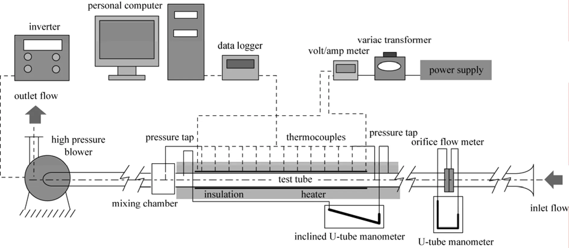
Figure 2 Schematic heat transfer experiment
The uncertainties of the reduced data were experimentally evaluated, adopting method of Ref. [28]. The maximum uncertainties of non-dimensional parameters were found to be ±4% for Reynolds number, ±5% for Nusselt number and ±7% for friction factor. The individual uncertainties of volumetric flow rate, pressure and temperature measurements were estimated to be within ±7%, ±2% and ±0.5%, respectively. All the present tests were conducted at the same inlet conditions of the test tube and the tube flow was expected to be fully developed because of the developing length of 31D before the tested section.
3 DA TA REDUCTION
During the test, air in the test section receives heat (Qair) from the electrical energy input to the system principally via the convective heat transfer mechanism. Thereby, Qairis assumed to be equal to the convective heat transfer within the test section.

The heat supplied by electrical winding in the test tube is found to be 4 to 8% higher than the heat absorbed by the fluid for thermal equilibrium test due to convection and radiation heat losses from the test section to surroundings. Thus, only the heat transfer rate absorbed by the fluid is taken for internal convective heat transfer coefficient calculation. The convection heat transfer rate from the test section can be expressed as

Substituting Eq. (2) into Eq. (3), yields


The average Nusselt number, Nu is estimated as follows:

The Reynolds number based on the average flow inlet velocity and the tube inlet diameter, is given by

where U is mean air velocity of the tube and ν is a kinematic viscosity of the working fluid. In fully developed flow, the friction factor (f) can be determined by measuring the pressure drop across the test tube length (L).

where ΔP is the pressure drop across the test tube measured by U-tube manometers, L is the test tube length and U is the mean air velocity at the entrance of the test section which was calculated from volumetric flow rate divided by the cross-section area of the tube. D is the inner diameter of the test tube at the inlet. The values of the thermo-physical properties of air were evaluated at the bulk fluid temperature from equation (4).
For a constant pumping power,

Eq. (10) can be rewritten in terms of friction and Reynolds number as:
Regarding to the suggestion by Webb and Kim [29], the thermal performance factor η, is defined as the ratio of the htof an augmented tube to that of a plain tube and hpat the same pumping power. The thermal performance factor can be expressed in terms of Nusselt number and friction factor as

where pp means pumping power.
4 RESUL TS AND DISCUSSION
4.1 Validation of the Experimental Setup
In this section, the results of heat transfer (in the form of Nusselt number), pressure drop (in the form of friction factor) and thermal performance factor associated by the tube fitted with ring-turbulators and twisted tapes, are described and discussed. To validate the present plain tube and other experimental facilities, the experiment was firstly conducted without any enhancement device. The present experimental results were then compared with the predictions obtained from theprevious correlations (correlation of Dittus-Boelter for Nusselt number and correlation of Blasius for friction factor), in order to evaluate their agreements.
Nusselt number correlations:
Correlation of Dittus-Boelter,

Friction factor correlations:
Correlation of Blasius,

Figure 3 shows that the Nusselt numbers of the present plain tube agree well with those obtained from the Dittus-Boelter correlation within ±4.9%. The results also show that Nusselt number almost increases linearly with increasing Reynolds number. Comparison in Fig. 4 reveals that the friction factors between experimental results and results predicted by Blasius correlation are in good agreement within ±5.7%.

Figure 3 Confirmation of Nusselt number for plain tubeplain tube; Dittus-Boelter

Figure 4 Confirmation of friction factor for plain tubeplain tube; Blasius
The Nusselt number and friction factor for the present plain tube are correlated as follows:
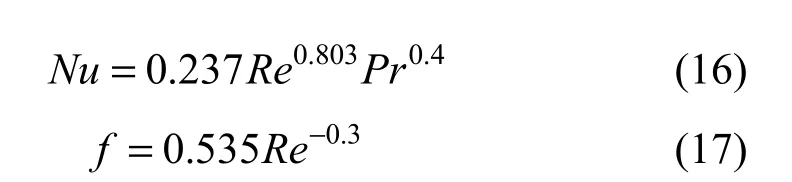
The comparisons between the experimental and the predicted data of Eqs. (16) and (17) reveal that the mean deviations of the predicted Nusselt number (Nu) and friction factor ( f ) for the present plain tube are 1.5% and 0.6%, and the corresponding maximum deviations for them are 2.3% and 1%, respectively.
4.2 Heat transfer
Figure 5 displays the variation of Nusselt number with Reynolds number of the plain tube, the tubes with circular-ring turbulators alone and the tubes with compound devices (circular-ring turbulator together with twisted tapes). The figure also shows the effect of pitch ratio of circular-ring turbulator and twist ratio of twisted tape. For all tubes, Nusselt number increases with increasing Reynolds number, the maximum Nusselt number was obtained at the highest Reynolds number (Re=20000). It is obvious that applying circular-ring turbulator results in a significant increase in Nusselt number above the plain tube. The simultaneous use of circular-ring turbulator and twisted tape as a compound device gives a further increase of Nusselt number, attributed to the combined effect of reverse/ separation flow by the circular-ring turbulator and swirl flow by the twisted tape. At similar operating conditions, the mean Nusselt number of using the compound devices is higher than that of employing the circular-ring alone and the plain tube around 25.8% and 20.6%, respectively. At the same Reynolds number, the Nusselt number increases with decreasing pitch ratio of circular-ring and/or twist ratio of twistedtape. Over the tested range, the maximum Nusselt number is obtained with the use of the compound device at the smallest pitch ratio (l/D=1.0) and twist ratio (y/W=3.0). This is attributed to the increase of heat transfer area as well as the increase of turbulent intensity imparted to the flow, leading to a better mixing of the fluid between the core and the tube wall region. It is also observed that the effect of the CRT pitch ratio is more prominent than that of the twist ratio. The mean Nusselt number associated by the circular ring with the lowest pitch ratio (l/D=1.0) is higher than those induced by the circular rings with l/D=1.5 and 2.0 around 16.9% and 32.6%, respectively. Meanwhile the mean Nusselt number of the tape with y/W=3.0 is higher than those with y/W=4.0 and 5.0 at about 11.4% and 23.3%, respectively.

Figure 5 Variation of Nusselt number with Reynolds number for the tubes with heat transfer enhancement devices
Figure 6 shows the Nusselt number ratio, Nut/Nup, against the Reynolds number value. It is clearly seen that the Nusselt number ratio value tends to decrease with the rise of Reynolds number. This signifies that the heat transfer improvement is more efficient at low Reynolds number. This can be simply explained that at lower Reynolds number, the thermal boundary is thicker, thus the disruption of the boundary by the circular-ring and twisted tape insert is more recognizable. The Nusselt number ratio values of all cases are above unity. This indicates an advantageous gain of using the tubes with circular ring and twisted tape insert over the plain tube.

Figure 6 Variation of Nusselt number ratio with Reynolds number for the tube s with heat tr ansfer enhancement devices
4.3 Pressure drop
The variation of the pressure drop in terms of friction factor across the test section with Reynolds number is portrayed in Fig. 7. For all cases, the friction factor tends to reduce with increasing Reynolds number. At a given Reynolds number, the tubes with compound devices possess higher friction factors than the tubes with circular-rings alone and also the plain tube. This is due the dissipation of dynamic pressure of the fluid caused by the combined effects of (1) the flow obstruction of circular-ring and twisted tape (2) the reverse, separation and swirl flows induced by the devices and (3) the increase of flow contact area. As shown in the figure, mean friction factor in the tube with compound devices is higher than those in the tube with circular-ring alone around 82.8% and 17.6 times of the plain tube, respectively. Similar to Nusselt number, friction factor increases with decreasing pitch ratio of circular-ring and decreasing twist ratio of twisted tape. The maximum friction factor is achieved with the compound device consisting of circular-ring turbulator with the smallest pitch ratio (l/D=1.0) and twisted tape with the smallest twist ratio (y/W=3.0). The mean friction factor induced by the circular ring with the lowest pitch ratio (l/D=1.0) is higher than those given by the circular rings with l/D=1.5 and 2.0 at around 42.3% and 75.5%, respectively. The mean friction factor generated by the twisted tape with smallest twist ratio (y/W=3.0) is higher than those induced by the twisted tapes with y/W=4.0 and 5.0 by around 17.2% and 37.6%, respectively.
Figure 8 shows the variation of friction factor ratio, ft/fp, with Reynolds number. It is seen that the friction factor ratio tends to increase with the rise of Reynolds number and the decreases of pitch ratio (l/D) and twist ratio and (y/W). According to the figure, the average/mean friction factor generated by the compound devices consisting of the twisted tape at the smallest twist ratio (y/W=3.0) and the circular rings with l/D=1.0, 1.5 and 2.0 are respectively, found to be about 33.8, 22.7 and 17 times of that for the plain tube.
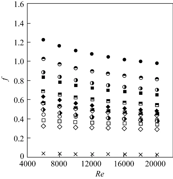
Figure 7 Variation of friction factor with Reynolds number for the tubes with heat transfer enhancement devices

Figure 8 Variation of frictio n factor ratio with Reynolds number for the tube s with heat tr ansfer enhancement devices
4.4 Thermal performance factor
The effect of using the circular-ring turbulator in conjunction with twisted tape on thermal performance factor based on the same pumping power is depicted in Fig. 9. This ultimate factor beyond unity can be used as the criteria for the proper enhancement devices as well as operating condition. As can be seen from Fig. 9, the performance factors are all greater than unity (η≥1) for all enhancement devices. In addition, the performance factor tends to decrease as Reynolds number increases. The results also reveal that the performance factor increases with the reduction of the pitch ratio (l/D) and twist ratio (y/W). The performance factors of the compound devices are consistently higher than those of the circular-rings alone. This signifies the beneficial gain in view point of energy saving by using both circular-ring and twisted tape over the circular-ring alone. Roughly, the mean thermal performance factor of the compound device is higher than that of the circular-ring alone by 6.3%. For the present Re range studied, the maximum thermal performance factor of 1.42, given by the compound enhancement devices is found at the lowest Reynolds number, l/D=1.0 and y/W=3.0.

Figure 9 Variation of therm al performance factor with Reynolds number for the tu bes w ith he at tr ansfer e nhancement devices
4.5 Empirical correlations and their accuracies
The Nusselt number, friction factor and thermal performance factor values of the circular-ring alone as well as the compound device (circular-ring in conjunction with twisted tape) at various pitch ratios (l/D=1.0, 1.5 and 2.0) and twist ratios (y/W=3.0, 4.0 and 5.0) are correlated (with the average relative errors in brackets) as follows:
For circular-ring alone

For compound device

Evidently, the experimental data of Nusselt number, friction factor, thermal performance factor, are well represented by the above correlations.
4.6 Comparison with the previous work
Figures 10 to 12 show the comparisons of the present results for Nusselt number, friction factor and thermal performance factor with those in a previous work [7]. As seen in Fig. 10, under similar conditions, the Nusselt numbers in the present work (and the combined device consisting of CRT and TT as well) are consistently higher than those in [7] (only CRT used). The superior heat transfer in the present work is attributed to the combined effects of turbulent flow (by CRT) and swirl flow (by TT) resulting in more effective thermal eruption and better temperature mixing. From Fig. 11, in spite of their higher Nusselt numbers, friction factors for generated by all combined devices in the present work are significantly lower than those obtained from the use of only CRT at l/D=6.0, d/D=0.5 and comparable with those achieved from the utilization of only CRT at l/D=6.0, d/D=0.6in [7]. Regarding to the comparisons of Nusselt number and friction factor mentioned above, the consequent thermal performance factors in the present work are higher (Fig. 12). This is attributed to the prominent effect of an advantage by the use of CRT and TT (an increase of Nusselt number relative to that of the plain tube) over a disadvantage one (an increase of friction factor relative to that of the plain tube) as compared to the results by the use of only CRT [7].

Figure 10 Comparison of Nusselt number of the presentCRT and TT with those in the previous work [7]
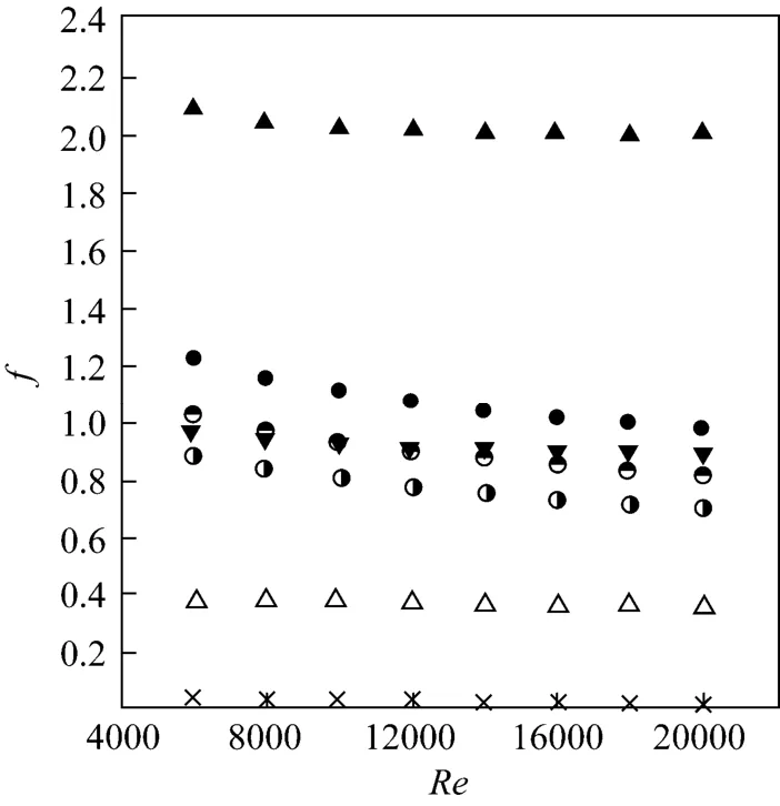
Figure 11 Comparison of friction factor of the present CRT and TT with those in the previous work [7]

Figure 12 Comparison of thermal performance factor of the present CRT and TT with those in [7]
5 CONCLU SIONS
In the present study, detailed heat transfer measurements were conducted in order to understand the heat transfer and friction factor inside tube inserts. The behaviors of the compound devices consisting of (1) circular-ring turbulators (CRT) with three different pitch ratios of l/D=1.0, 1.5 and 2.0 and (2) twisted tape swirl-generators (TT) with three different twist ratios of y/W=3.0, 4.0 and 5.0, were determined. The circular-ring alone and the plain tube were also tested for comparison. The order of heat transfer enhancement associated by the compound devices are about 2.36 to 4.47 times the plain tube which are accompanied by pressure loss ranging from 10.7 to 31.2 times, depending on the pitch ratio (l/D) and twist ratio (y/W) and Reynolds number (Re) values. It is found that the heat transfer rate increases with increasing Reynolds number and decreasing pitch/twist ratio. Comparatively, the compound enhancement devices provide higher heat transfer rate than the circular-ring alone around 25.8%. At a constant pumping power, the thermal performance factor for all enhancement devices is found to be higher than unity. The maximum thermal performance factor of 1.42 is reached at the lowest Reynolds number, l/D=1.0 and y/W=3.0. In addition, the correlations for Nusselt number, friction factor and thermal performance factor for the compound devices were developed as a function of the pitch ratio (l/D) and twist ratio (y/W), Prandtl number (Pr) and Reynolds number (Re) in this article.
ACKNOWLEDGEMENTS
The authors gratefully acknowledge the office of higher education commission CHE and mahanakorn university of technology (MUT).
NOMENCLATURE
A heat transfer surface area, m−2
Cp,airspecific heat capacity of air, kJ·kg−1·K−1
D inner diameter of test tube or inner diameter of CRT, m
d outer diameter of CRT, m
f friction factor
h mean heat transfer coefficient, W·m−2·K−1
I current, A
k thermal conductivity of air, W·m−1·K−1
L length of the test tube, m
l pitch length of CRT, m
Nu Nusselt number
Pr Prandtl number
ΔP pressure drop, Pa
Q heat transfer rate, W
Re Reynolds number
T temperature, K
T˜ mean temperature, K
t thickness of the test tube, m
U mean axial velocity, m·s−1
V voltage, V
ν kinematic viscosity, Ns·m−2
W tape width, m
y twist length, m
η thermal performance factor
ρ fluid density, kg·m−3
Subscripts
b bulk
i inlet
m mean
o outlet
p plain tube
t
turbulator
w wall
REFERENCES
1 Eiamsa-ard, S., Promvonge, P., “Experimental investigation of heat transfer and friction characteristics in a circular tube fitted with V-nozzle turbulators”, Int. Comm. Heat Mass Transfer, 33, 591-600 (2006).
2 Promvonge, P., Eiamsa-ard, S., “Heat transfer and turbulent flow friction in a circular tube fitted with conical-nozzle turbulators”, Int. Comm. Heat Mass Transfer, 34, 72-82 (2007).
3 Yakut, K., Sahin, B., Canbazoglu, S., “Performance and flow-induced vibration characteristics for conical-ring turbulators”, Appl. Energy, 79, 65-76 (2004).
4 Yakut, K., Sahin, B., “Flow-induced vibration analysis of conical rings used of heat transfer enhancement in heat exchanger”, Appl. Energy, 78, 273-288 (2004).
5 Promvonge, P. “Heat transfer behaviors in round tube with conical ring inserts”, Energy Conver. Manag., 49, 8-15 (2008).
6 Eiamsa-ard, S., Promvonge, P., “Thermal characterization of turbulent tube flows over diamond-shaped elements in tandem”, Int. J. Therm. Sci., 49, 1051-1062 (2010).
7 Kongkaitpaiboon, V., Nanan, K., Eiamsa-ard, S., “Experimental investigation of convective heat transfer and pressure loss in a round tube fitted with circular-ring turbulators”, Int. Comm. Heat Mass Transfer, 37, 568-574 (2010).
8 Kongkaitpaiboon, V., Nanan, K., Eiamsa-ard, S., “Experimental investigation of heat transfer and turbulent flow friction in a tube fitted with perforated conical-rings”, Int. Comm. Heat Mass Transfer, 37, 560-567 (2010).
9 Durmus, A., “Heat transfer and exergy loss in cut out conical turbulators”, Energy Conver. Manag., 45, 785-796 (2004).
10 Kiml, R., Mochizuki, S., Murata, A., Stoica, V., “Effects of rib-induced secondary flow on heat transfer augmentation inside a circular tube”, J. Enhanced Heat Transfer, 10, 9-20 (2003).
11 Kiml, R., Magda, A., Mochizuki, S., Murata, A., “Rib-induced secondary flow effects on local circumferential heat transfer distribution inside a circular rib-roughened tube”, Int. J. Heat Mass Transfer, 47, 1403-1412 (2004).
12 Jaisankar, S., Radhakrishnan, T.K., Sheeba, K.N., Suresh, S., “Experimental investigation of heat transfer and friction factor characteristics of thermosyphon solar water heater system fitted with spacer at the trailing edge of left-right twisted tapes”, Energy Conver. Manag., 50, 2638-2649 (2009).
13 Liao, Q., Xin, M.D., “Augmentation of convective heat transfer inside tubes with three-dimensional internal extended surfaces and twisted-tape inserts”, Chem. Eng. J., 78, 95-105 (2000).
14 Zimparov, V., “Enhancement of heat transfer by a combination of three-start spirally corrugated tubes with a twisted tape”, Int. J. Heat Mass Transfer, 44, 551-574 (2001).
15 Zimparov, V., “Enhancement of heat transfer by a combination of a single-start spirally corrugated tubes with a twisted tape”, Exp. Therm. Fluid Sci., 25, 535-546 (2002).
16 Hong, M.N., Deng, X.H., Huang, K., Li, Z.W., “Compound heat transfer enhancement of a converging-diverging tube with evenly spaced twisted-tapes”, Chin. J. Chem. Eng., 15, 814-820 (2007).
17 Pramanik, D., Saha, S.K., “Thermohydraulics of laminar flow through rectangular and square ducts with transverse ribs and twisted tapes”, Int. J. Heat Transfer Trans., 128, 1070-1080 (2006).
18 Bharadwaj, P., Khondge, A.D., Date, A.W., “Heat transfer and pressure drop in a spirally grooved tube with twisted tape insert”, Int. J. Heat Mass Transfer, 52, 1938-1944 (2009).
19 Al-Fahed, S., Chamra, L.M., Chakroun, W., “Pressure drop and heat transfer comparison for both microfin tube and twisted-tape inserts in laminar flow”, Exp. Therm. Fluid Sci., 18, 323-333 (1998).
20 Thianpong, C., Eiamsa-ard, P., Wongcharee, K., Eiamsa-ard, S.,“Compound heat transfer enhancement of a dimpled tube with a twisted tape swirl generator”, Int. Comm. Heat Mass Transfer, 36, 698-704 (2009).
21 Promvonge, P., Eiamsa-ard, S., “Heat transfer behaviors in a tube with combined conical-ring and twisted-tape insert”, Int. Comm. Heat and Mass Transfer, 34, 849-859 (2007).
22 Promvonge, P., “Thermal augmentation in circular tube with twisted tape and wire coil turbulators”, Energy Conver. Manag., 49, 2949-2955 (2008).
23 Eiamsa-ard, S., Nivesrangsan,P., Chokphoemphun S., Promvonge, P., “Influence of combined non-uniform wire coil and twisted tape inserts on thermal performance characteristics”, Int. Comm, Heat Mass Transfer, 34, 849-859 (2010).
24 Pal, P.K., Saha, S.K., “Thermal and friction characteristics of laminar flow through square and rectangular ducts with transverse ribs and twisted tapes with and without oblique teeth”, J. Enhanced Heat Transfer, 17, 1-21 (2010).
25 Zhang, Y.M., Azad, G.M., Han, J.C., Lee, C.P., “Turbulent heat transfer enhancement and surface heating effect in square channels with wavy, and twisted tape inserts with interrupted ribs”, J. Enhanced Heat Transfer, 7, 5-49 (2000).
26 Murugesan, P., Mayilsamy, K., Suresh, S., “Heat transfer and friction factor studies in a circular tube fitted with twisted tape consisting of wire-nails”, Chin. J. Chem. Eng., 18, 1038-1042 (2010).
27 Japanese Industrial Standard, “Measurement of Fluid Flow by Means of Orifice Plates, Nozzles and Venturi Tubes”, Japanese Standards Association, Japan, JIS Z 8762-1988 (1988).
28 ANSI/ASME, “Measurement Uncertainty”, PTC 19, 1-1985. Part I (1986).
29 Webb, R.L., Kim N.H., Principles of Enhanced Heat Transfer, 2nd edition, Taylor& Francis Group, New York (2005).
2011-09-22, accepted 2011-12-29.
* Supported by the Thailand Research Fund (TRF).
** To whom correspondence should be addressed. E-mail: smith@mut.ac.th
杂志排行

Chinese Journal of Chemical Engineering的其它文章
- Preparation of Mesoporous Carbons from Acrylonitrile-methyl Methacrylate Copolymer/Silica Nanocomposites Synthesized by in-situ Emulsion Polymerization*
- Immobilization of Papain in Biosilica Matrix and Its Catalytic Property*
- Comparison on Thermal Conductivity and Permeability of Granular and Consolidated Activated Carbon for Refrigeration*
- Effect of Hydrogen Reduction of Silver Ions on the Performance and Structure of New Solid Polymer Electrolyte PEI/Pebax2533/AgBF4Composite Membranes*
- Synthesis of 2-Methyl-4-methoxyaniline from o-Nitrotoluene Using Pt/C and Acidic Ionic Liquid as Catalyst System*
- Adsorption and Desorption Behavior of Tannic Acid in Aqueous Solution on Polyaniline Adsorbent*