Numerical simulation of hydro-elastic problems with smoothed particle hydrodynamics method*
2013-06-01LIUMoubin刘谋斌SHAOJiaru邵家儒
LIU Mou-bin (刘谋斌), SHAO Jia-ru (邵家儒)
Institute of Mechanics, Chinese Academy of Sciences, Beijing 100190, China, E-mail: liumoubin@imech.ac.cn LI Hui-qi (李慧琦)
School of Information and Electronics, Beijing Institute of Technology, Beijing 100081, China
(Received December 18, 2012, Revised May 27, 2013)
Numerical simulation of hydro-elastic problems with smoothed particle hydrodynamics method*
LIU Mou-bin (刘谋斌), SHAO Jia-ru (邵家儒)
Institute of Mechanics, Chinese Academy of Sciences, Beijing 100190, China, E-mail: liumoubin@imech.ac.cn LI Hui-qi (李慧琦)
School of Information and Electronics, Beijing Institute of Technology, Beijing 100081, China
(Received December 18, 2012, Revised May 27, 2013)
Violent free surface flows with strong fluid-solid interactions can produce a tremendous pressure load on structures, resulting in elastic and even plastic deformations. Modeling hydro-elastic problems with structure deformations and a free surface breakup is difficult by using routine numerical methods. This paper presents an improved Smoothed Particle Hydrodynamics (SPH) method for modeling hydro-elastic problems. The fluid particles are used to model the free surface flows governed by Navier-Stokes equations, and the solid particles are used to model the dynamic movement and deformation of the elastic solid objects. The improved SPH method employs a Kernel Gradient Correction (KGC) technique to improve the computational accuracy and a Fluid-Solid Interface Treatment (FSIT) algorithm with the interface fluid and solid particles being treated as the virtual particles against their counterparts and a soft repulsive force to prevent the penetration and a corrective density approximation scheme to remove the numerical oscillations. Three typical numerical examples are simulated, including a head-on collision of two rubber rings, the dam break with an elastic gate and the water impact onto a forefront elastic plate. The obtained SPH results agree well with experimental observations and numerical results from other sources.
Smoothed Particle Hydrodynamics (SPH), hydro-elasticity, Fluid-Structure Interaction (FSI), artificial stress
Introduction
Violent free surface flows with strong fluid-structure interactions are widely observed in hydrodynamics and ocean engineering. They can produce a tremendous hydro-pressure load on the solid structures and cause the structure to deform elastically or even plastically. They are usually referred to as hydro-elasticity and hydro-plasticity. For example, under extreme weather conditions, the rolling and breaking up of the water surface can produce strong slamming effects on hull structures, offshore platforms and nearby buildings, and can further lead to local damages and global instability of the structures. The large amplitude liquid sloshing in oil or Liquefied Natural Gas (LNG) ships can result in a very high impact pressure on the container, which can damage the hull walls and further lead to the leakage of oil, and even capsize ships. Therefore, how to effectively model the strong fluidsolid interaction in hydro-elasticity is very important for applications in hydrodynamics and ocean engineering.
For modeling the fluid and solid dynamics, among the grid based numerical methods, the Finite Difference Method (FDM), the Finite Volume Method (FVM) and the Finite Element Method (FEM) are most frequently used. They are currently the dominant methods in numerical simulations for solving practical problems in engineering and science. Despite the great success, the grid based numerical methods suffer from difficulties, which limit their applications in many types of complicated problems such as the hydro-elastic problems with violent deformation and even break up of the free surfaces, and movement and deformation of the solid structures. For Lagrangian grid-based methods such as FEM, a grid is attached on, moves and deforms with the moving objects. It is thereforeeasy to obtain the time-history of the movement and convenient to treat or track the moving features such as the free surfaces and the deformable interfaces. However it is very difficult to treat a large deformation due to possible mesh entanglement. In contrast, for Eulerian grid based methods such as FDM and FVM, a computational grid is fixed on the computational domain and there is no problem to treat large deformation. However, it is very difficult to treat or track the moving features and special algorithms are usually necessary, which are usually complicated and can induce errors.
For modeling Fluid-Structure Interaction (FSI) problems, both Eulerian and Lagrangian methods are usually used. Typical approaches include the Coupled Eulerian Lagrangian (CEL) and the Arbitrary Lagrange Eulerian (ALE). The CEL approach employs both the Eulerian and Lagrangian methods in separate (or with some overlap) regions of the problem domain. One of the most common practices is to discretize solids in a Lagrangian frame, and fluids (or materials behaving like fluids) in a Eulerian frame. The Lagrangian region and the Eulerian region continuously interact with each other through a coupling module in which the computational information is exchanged either by mapping or by special interface treatments between these two sets of grids. The ALE is closely related to the rezoning techniques for the Lagrangian mesh, and aims to move the mesh independently of the materials so that the mesh distortion can be minimized. It is in a very quick development and is widely applied to problems with large deformation and strong FSIs. Unfortunately, even with the CEL and ALE formulations a highly distorted mesh can still introduce severe errors in numerical simulations.
During the last decades, effort has been focused on the development of the next generation computational methods, the meshfree methods, such as the Moving Particle Semi-implicit (MPS)[1]method and the Smoothed Particle Hydrodynamics (SPH)[2]method. In the MPS, the governing equations are transformed into those of interactions among moving particles, and a semi-implicit algorithm is used to model the incompressible flows through solving the Poisson equation of pressure, while the other terms are explicitly calculated. The MPS method is widely applied to modeling free surface flows. The smoothed particle hydrodynamics is another popular meshfree, Lagrangian, particle method with some attractive features. The field variables (such as the density, the velocity, and the acceleration) can be obtained through discretizing the governing equations into a set of particles. The connectivity between particles is established as a part of the computation and can vary with time. Therefore, the SPH allows a straightforward handing of a very large deformation. The SPH was successfully used in solving multi-phase flows[3], heat conduction[4], elastic dynamics[5], liquid sloshing[6]and underwater explosion problems[7]. However, there are still some problems that need to be solved in the conventional SPH method, such as the stress instability, the low accuracy and the solid boundary treatment[8]. Also there are few papers dealing with the FSI problems by using the SPH method.
In this paper, an SPH model is built for simulating hydro-elastic problems with strong FSIs. The SPH model involves an improved particle approximation scheme and an enhanced fluid-solid interface treatment algorithm. In this purely meshfree model, the fluid particles are used to model the free surface flows governed by Navier-Stokes equations, and the solid particles are used to model the movement and deformation of the moving solid structures. The interface fluid and solid particles are treated by the virtual particles of their counterparts with consideration of the interaction of the neighboring fluid and solid particles as the fluid-solid interaction.
1. Equations of motion
1.1Governing equations
The governing motion of the fluid flow and the solid dynamics in the isothermal condition can be described by the following continuity and momentum equations

wherexi,vi,fi,ρdenote the position, the velocity, the external force and the density, respectively. The stress tensorσijcan be decomposed into the isotropic and deviatoric parts as

wherepis the isotropic pressure,τijis the deviatoric viscous stress, andδijis the Kronecker tensor.
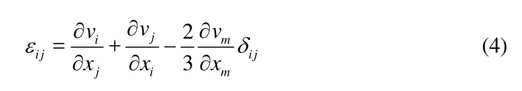
For a Newtonian fluid such as water, the viscous shear stress is proportional to the rate of shear strainεij(τij=μεij,μis the dynamic viscosity), andεijcan be described as
For the elastic solid objects, the change rate ofτijis given by
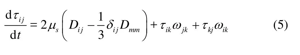
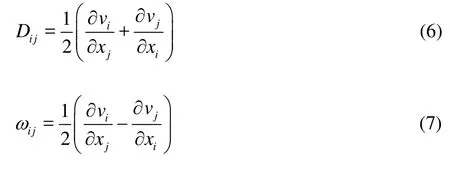
wheresμis the shear modulus,Dijandijωare the components of the rates of the deformation tensor and the rotational tensor, respectively. They can be written as:
To solve the equations of motion, the concept of artificial compressibility is used to model both the incompressible fluids and solids as slightly compressible ones using an artificial equation of state. A commonly used artificial equation of state is

whereρ0is the reference density, and it is taken as the initial density of the corresponding material.c0is the sound speed. For a fluid,(whereζis the compressibility modulus of the fluid), and for a solid,(whereKis the bulk modulus of the solid).
1.2SPH approximations and equations of motionAn SPH formulation is derived mainly in two steps, the kernel approximation and the particle approximation. The kernel approximation is to represent a function and its derivatives in a continuous form as an integral representation, and the approximation is based on the evaluation of the smoothed kernel function and it derivatives. In the particle approximation, the computational domain is first discretized by representing the domain with a set of the initial distribution of the particles representing the initial setting of the problem. Then the field variables on a particle are approximated by an averaged summation of the particles in the support domain[9]. Therefore, a function and its derivative can be described in the following form:


where <f(xa)> is the approximate value of particlea,f(xb) is the value off(x) associated with particleb,xaandxbare the corresponding position vectors,mis the mass,his the smooth length,Nis the number of the particles in the support domain,Wis the smoothed function. Using this method, the continuity and momentum equations can be described as

wherevab=va-vb.
By combining Eq.(3) with Eq.(12), the final momentum equation can be obtained as

2. Numerical aspects
2.1Kernel gradient correction
Hydro-elastic problems with strong FSIs are usually associated with changes and breakups of the free surfaces. When the wave front violently impacts the solid structures, the water particles can splash away from the bulky fluid, and then fall onto the bulky fluid. The changes and breakups of the free surfaces as well as the splashing and the falling of the water particles lead to a highly disordered particle distribution, which can seriously influence the computational accuracy of the SPH approximations. Hence an SPH approximation scheme of higher order accuracyand insensitive to the disordered particle distribution is necessary.
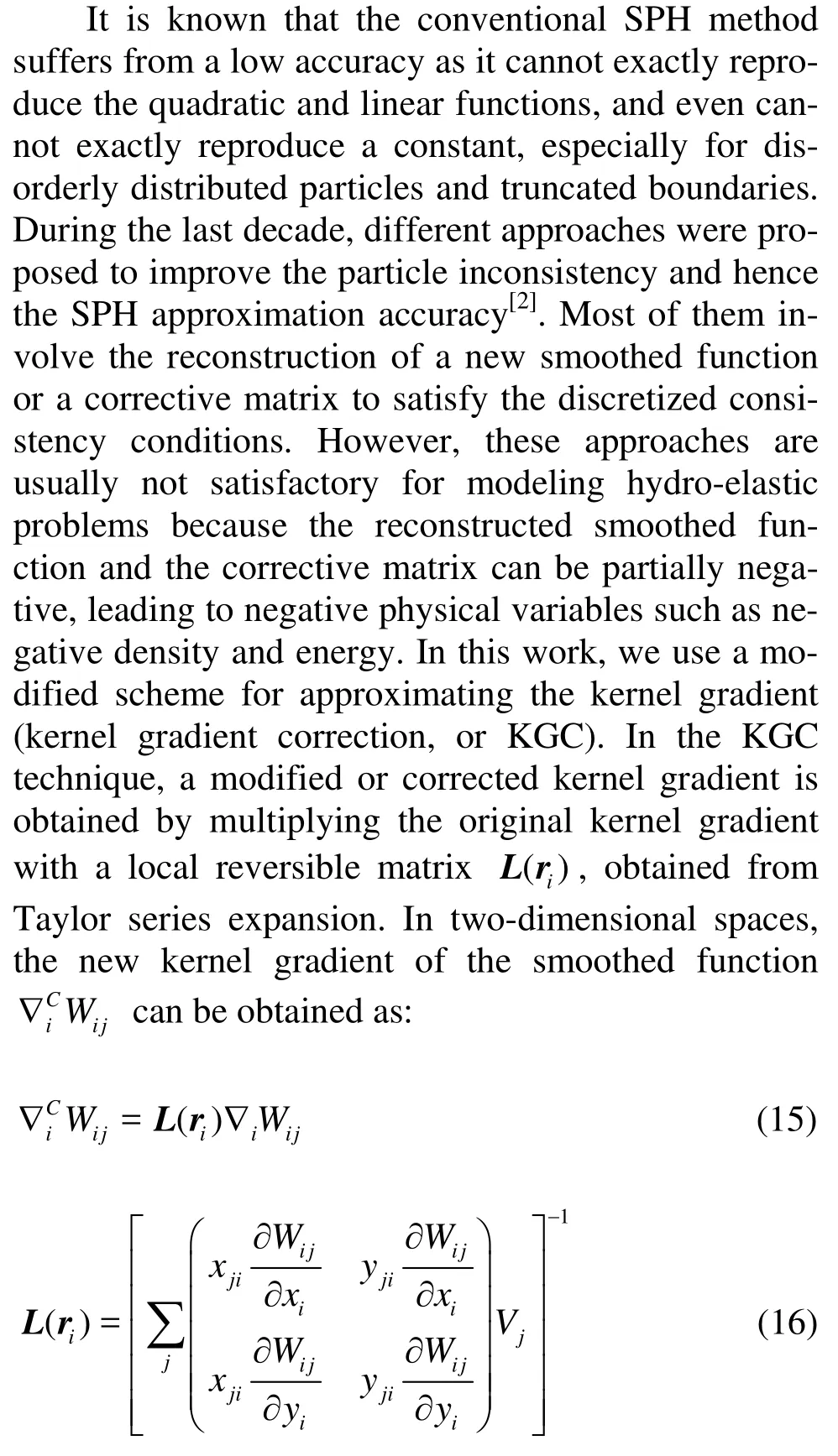
wherexji=xj-xi,yji=yj-yi. It is found that the SPH particle approximation scheme with kernel gradient correction is of second order accuracy. Another advantage is that it is convenient to implement KGC in the conventional SPH equations of motion as only the kernel gradient is corrected, and there is no need to significantly change the structure of the SPH computer programs and procedures of the SPH simulations.
2.2Artificial viscosity and artificial stress
In the SPH simulation, the artificial viscosityΠaband the artificial stressRijabfnare often added into the pressure term. The corrected momentum equation can be written as

The artificial viscosity can diffuse the sharp variations in the flow and dissipate the energy of high frequency terms. Here the Monaghan type artificial viscosity (Π) is added to the physical pressure term
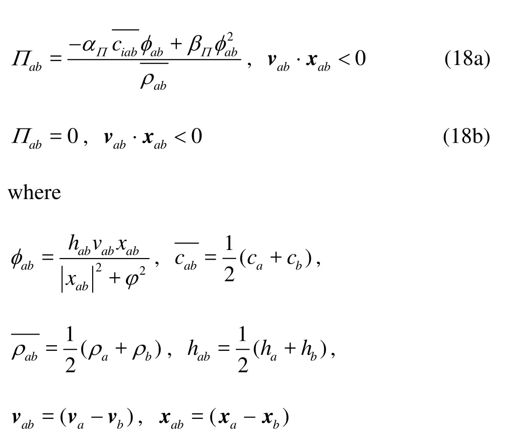
αΠandβΠare constants. The factorφ=0.1hijis inserted to prevent the numerical divergences when two particles are approaching each other.
For modeling the elastic solid objects, the particles are prone to clump together, and cause non-physical fractures in the material as in a tensile instability[9]. Therefore, an artificial stress[5]is used to remove or alleviate the tensile instability and it can be written as

To obtain the value ofRijin particlea, the principal stresses must be calculated from the following equations
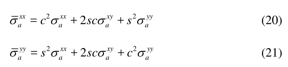
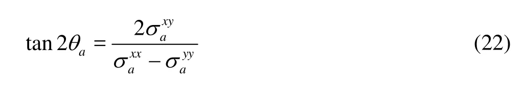
wherecandsrepresent cosaθand sinaθ,aθcan be obtained from
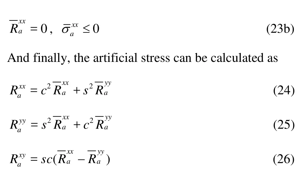
The transition variableRis calculated by the equation

2.3Fluid-solid interface treatment
The Solid Boundary Treatment (SBT) and the implementation of the solid boundary conditions are major challenges in the SPH simulation[10]. In order to model the solid boundary for moving rigid bodies or fixed solid walls, a coupled dynamic SBT (CD-SBT) algorithm was developed[11]. In the CD-SBT algorithm, two types of virtual particles (the repulsive particles and the ghost particles) are used to represent the solid obstacles. The repulsive particles are located right on the solid wall and can produce a suitable repulsive force on the approaching fluid particles near the solid boundary. Ghost particles are distributed in the obstacle area outside the solid boundary. The CD-SBT algorithm involves a soft repulsive force between repulsive particles and approaching fluid particles, and a higher order scheme to approximate the information of the virtual particles. Therefore it is effective to prevent the fluid particles from penetrating the solid walls and to avoid the pressure oscillation then to ensure an accurate pressure load[11].
As mentioned earlier, there were few paper dealing with the fluid-structure interactions by using the SPH method, and the fluid-solid interface is usually treated by using some kind of interface force. The interface force is usually dependent on the interface curvature, so the tangential and normal directions need to be calculated. It is usually difficult to do so in the particle methods such as the SPH and the MPS.
In this work, we further extend the CD-SBT algorithm for the treatment of the fluid-solid interface and the algorithm is called the coupled dynamic fluidsolid interface treatment (CD-FSIT). First in this CDFSIT algorithm, a soft, distance-dependent, pairwise repulsive force is applied along the centerline of the neighboring pairs of the fluid and solid particles to prevent them from penetrating each other. The repulsive force is the same as the repulsive force in the CD-SBT algorithm[11]and can be written as:


whereris the distance between two particles, and Δdis the initial distance of two adjacent particles. This soft repulsive force can prevent the unphysical particle penetration without obvious pressure disturbances as in the previous interface treatment algorithms with highly repulsive forces.
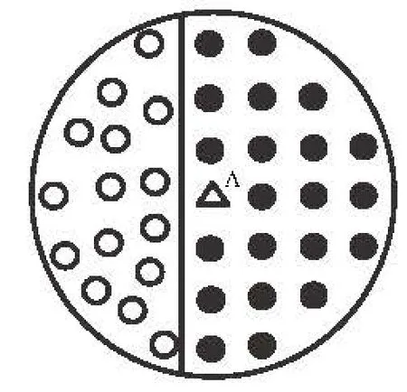
Fig.1 Illustration of the CD-FSIT algorithm: interface fluid and solid particles are treated by virtual particles and their counterparts

Fig.2 Illustration of the head-on collision of two rubber rings
Secondly, in this CD-FSIT algorithm, the interface fluid and solid particles are represented by the virtual particles and their counterparts as shown in Fig.1. Specifically, for a particle A (triangle in Fig.1) in the elastic solid region, the approximation of the physical variables on particle A is dependent on neighboring solid particles (filled circles in the support domain) and possible neighboring fluid particles (dotted circles in the support domain) if particle A is located at the interface area. The neighboring fluid particles are used as the virtual particles for particle A. Inapproximating the density of particle A, Eq.(11) cannot be directly used as it is valid only for particles from the same materials. For approximations with particles from different materials, the possible large density inhomogeneity may produce a large numerical oscillation in the interface region. Therefore, in the interface region, the density change rate (in the continuity equation) can be corrected by the density ratio of the solid particles to the fluid particles as follows

Fig.3 Simulation snapshots of the head-on collision of two rubber rings

Fig.4 Horizontal (a) and vertical (b) displacements of particles A and B

Fig.5 Illustration of dam-break with an elastic gate at the exit
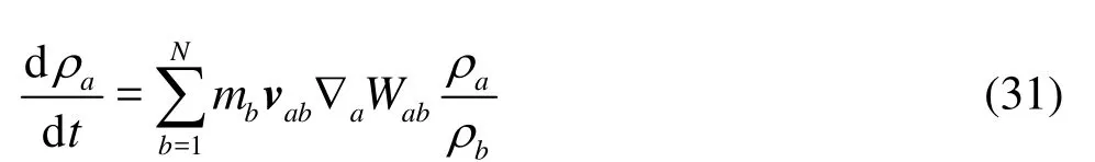

Fig.6 SPH simulation snapshots and experimental observations
It is clear that in Eq.(31), if particlebis from the same material as particlea(hereais the same as particle A in elastic solid objects), asρa≈ρb, Eq.(31) approaches Eq.(11). If particlebis a neighboring fluid particle, its contribution to dρa/dt(mbvab∇a⋅Wab) is underestimated as the mass (or density) of particlebis lower than that of particlea. Adding a corrective term ofρa/ρbcan help to balance the underestimation of the density change rate from particleb. The same idea applies to the numerical approximations of the interface fluid particles, and the density change rate of a certain fluid particle should be corrected by the density ratio of the fluid particles to the solid particles.
In summary, the CD-FSIT algorithm includes a soft repulsive force between approaching interface fluid and solid particles to prevent unphysical particle penetrations in the interface region, and a corrective density approximation scheme to remove the possible numerical oscillation due to a large density inhomogeneity. It can be demonstrated later on that this CDFSIT algorithm is effective to model hydro-elastic problems.
3. Numerical examples
3.1Head-on collision of two rubber rings
The effectiveness of the improved SPH in modeling incompressible fluid flows was previously demonstrated in a number of applications[12,13]. Here, in order to validate its effectiveness in dealing with the movement and the deformation of elastic solid objects, the head-on collision of two rubber rings is modeled firstly. Figure 2 shows the illustration of the head-on collision of two rubber rings. The two rubber rings are made of the same material with the same geometric dimensions and physical properties. Thehead-on impacting speed is 50 m/s, and the relative velocity is 100 m/s. The inner and outer radii of the rubber rings are 0.03 m and 0.04 m, respectively, and the initial distance between the centers is 0.09 m. The density of the rubber is 1 010 Kg/m3, the shear modulus is8
1.6× 10 Pa, and the initial sound speed is 852 m/s. About 18000 particles are used with an initial particle spacing of 0.0005 m. The time step is taken as 0.5×10⁻⁷s, and the coefficient of the artificial stress is taken ase=0.3,q=4.
Figure 3 shows the simulation snapshots of the head-on collision of two rubber rings using the improved SPH method. The obtained SPH results agree well with those obtained by Yang[14]who used a Lagrangian mesh method. As shown in Fig.3, as two rubber rings approach and impact each other, a large deformation occurs, and the initial circular ring in the interface area is quickly flattened (Fig.3(b)). As the stress wave propagates in the two rubber rings, the initial circular rings are elongated vertically and turn to be elliptic (Fig.3(c)). Due to the elastic nature of the solid objects, the two rubber rings tend to bounce back, gradually restore their original shape (Figs.3(d) and 3(e)) and are further elongated horizontally (Fig.3(f)). The elongation in vertical and horizontal directions lasts several periods with a gradually decayed amplitude, while the two rubber rings finally restore their original circular shape.
To further investigate the head-on collision process, the positions of particles A and B (see Fig.2) are tracked. Figure 4 shows the horizontal and vertical displacements of particles A and B. It is clear that during the head-on collision process, particles A and B stay on the horizontal line (Fig.4(b)). Right after the sudden collision, particles A and B stay at the same position (with small oscillations) for a long period of time to accumulate deformation. Later on, as the two rubber rings tend to bounce back and separate from each other, particle A moves along the negative direction and particle B moves along the positive direction. The obtained horizontal displacements of particles A and B are therefore anti-symmetric.
3.2Dam break with an elastic gate
In this case, a dam break is modeled, in which an elastic gate is placed at the exit (see Fig.5). The water pressure from the dam break can cause movement and deformation of the elastic plate. The improved SPH method is used to simulate this typical hydro-elastic problem. As shown in Fig.5, the top of the gate is clamped and the bottom is free. The height and width of the water are 0.14m and 0.1 m, respectively. The elastic gate is 0.079 m high and 0.005 m thick. The density and compressibility modulus of water are
1 000 Kg/m3and 2×10⁶N/m2, respectively. The density, the bulk and shear moduli of the elastic gate are 1 100 Kg/m3, 2×10⁷and 4.27×10⁶N/m2, respectively. In the simulation, the time step is 2.5×10⁻⁶s, the coefficient of the artificial stress is taken ase=0.3,q=4, and about 22 000 particles are used.
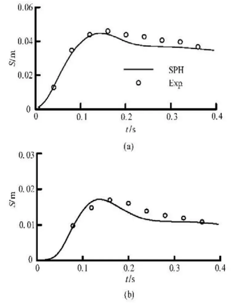
Fig.7 Horizontal (a) and vertical (b) displacements of the free end of the elastic gate
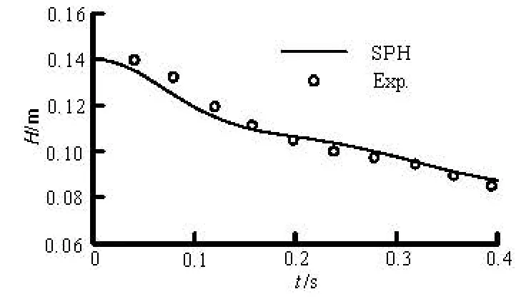
Fig.8 Time history of water level
Figure 6 shows the SPH simulation snapshots and the corresponding experimental observations. It is shown that before the dam break, both the water and the elastic gate are in a still state. After the sudden removal of the clamp, under the static water pressure, the elastic gate will deform and gradually open. The contained water is discharged from the gate and this leads to a large displacement of the elastic gate with a large water current out of the exit. Figure 7 shows the horizontal and vertical displacements of the free end of the elastic gate in the experimental observations. It is noted that with the movement of the elastic gate, more water flows out of the exit with a larger pressure load on the elastic gate, which further increases the movement and the deformation of the elastic gate until maximal displacements are reached. Later as the water height reduces, the pressure load on the elastic gatealso reduces, leading to smaller displacements. Figure 7 shows the peak values both in the horizontal and vertical displacements. Figure 8 shows the comparisons of the water level from the SPH simulation and the experimental observation. It is obvious that for both displacements and water height, the obtained SPH results agree well with experimental observations[15].
3.3Water impact onto a forefront elastic plate


Fig.9 Illustration of the water impact onto a forefront elastic plate
Figure 10 shows the simulation snapshots from the PFEM (left) and the SPH (right) at different instants. Figure 11 shows the time history of the horizontal displacement of the free end of the elastic plate. From Fig.10 and Fig.11, at about 0.14 s, the dam break flow impacts the elastic plate, causing its movement and deformation. At about 0.26 s, the displacement of the elastic plate reaches a maximum value. Later as the water level gradually reduces, the pressure impact on the elastic plate also reduces, leading to smaller displacements. At further later stages, as the water particles bounce back from the right solid wall, and move leftwards in the container, the elastic plate has negative displacements (moves leftwards). It is clear that for both the flow pattern and the displacement of the elastic plate, the obtained numerical results from the present SPH method in general agree well with those from PFEM[16]. At very late stages (T>0.6 s), there are some discrepancies, basically due to the complex turbulence and cavity effects.

Fig.10 Simulation snapshots from PFEM (left) and SPH (right) at different instants

Fig.11 Horizontal displacement of the free end of the elastic plate
4. Conclusion
This paper presents an improved SPH method for modeling hydro-elastic problems with violent free surface flows and strong fluid-structure interactions. The improved SPH method involves an improved numerical approximation scheme of the kernel gradient correction and an enhanced fluid-solid interface treatment algorithm. This purely meshfree method can well describe the deformation and the breakup of the free surfaces, and the movement and the deformation of ela-stic solid objects. The KGC technique improves the computational accuracy especially for disorderly distributed particles and truncated boundaries. The coupled dynamic fluid-solid interface treatment algorithm can well deal with the FSI without unphysical particle penetration and numerical oscillations. The effectiveness of the SPH model is demonstrated by three numerical examples, including the head-on collision of two rubber rings, the dam break with an elastic gate, and the water impact onto a forefront elastic plate. The obtained results agree well with results from other sources.
[1] KOSHIZUKA S., OKA Y. Moving-particle semi-implicit method for fragmentation of incompressible fluid[J]. Nuclear Science and Engineering, 1996. 123(3): 421-434.
[2] LIU M. B., LIU G. R. Smoothed particle hydrodynamics (SPH): An overview and recent developments[J]. Archives of Computational Methods in Engineering, 2010, 17(1): 25-76.
[3] MONAGHAN J. J., KOCHARYAN A. SPH simulation of multi-phase flow[J]. Computer Physics Communications, 1995, 87(1): 225-235.
[4] JIANG Tao, OUYANG Jie and LI Xue-juan et al. The first order symmetric SPH method for transient heat conduction problems[J]. Acta Physica Sinica, 2011, 60(9): 090206(in Chinese).
[5] GRAY J. P., MONAGHAN J. J. and SWIFT R. P. SPH elastic dynamics[J]. Computer Methods in Applied Mechanics and Engineering, 2001, 190(49): 6641-6662.
[6] CHEN Z., ZONG Z. and LI H. T. et al. An investigation into the Pressure on Solid Walls in 2D sloshing using SPH method[J]. Ocean Engineering, 2013, 59: 129-141.
[7] LIU M. B., LIU G. R. and LAM. K. Y. et al. Smoothed particle hydrodynamics for numerical simulation of underwater explosion[J]. Computational Mechanics, 2003, 30(2): 106-118.
[8] LIAN Y. B., ZHANG X. and ZHOU X. et al. Numerical simulation of explosively driven metal by material point method[J]. International Journal of Impact Engineering, 2011, 38(4): 238-246.
[9] LIU G. R., LIU M. B. Smoothed particle hydrodynamics: A meshfree particle method[M]. Singapore: World Scientific, 2003.
[10] GONG Kai, LIU Hua and WANG Ben-long. Water entry of a wedge based on SPH model with an improved boundary treatment[J]. Journal of Hydrodynamics, 2009, 21(6): 750-757.
[11] LIU Mou-bin, SHAO Jia-ru and CHANG Jian-zhong. On the treatment of solid boundary in smoothed particle hydrodynamics[J]. Science China Technological Sciences, 2012, 55(1): 1-10.
[12] YAKUTOVICH M. V., CARE C. M. and NEWTON J. P. et al. Mesh-free modeling of liquid crystals using modified smoothed particle hydrodynamics[J]. Physical Review E, 2010, 82(4): 041703.
[13] SHAO J. R., LI H. Q. and LIU G. R. et al. An improved SPH method for modeling liquid sloshing dynamics[J]. Computers and Structures, 2012, 100-101: 18-26.
[14] YANG Gang. The improvement and some typical application of smoothed particle hydrodynamics[D]. Doctoral Thesis, Changsha, China: Hunan University, 2010(in Chinese).
[15] ZHOU Guang-zhen, CHEN Zhi-hai and GE Wei et al. SPH simulation of oil displacement in cavity-fracture structures[J]. Chemical Engineering Science, 2010, 65(11): 3363-3371.
[16] IDELSOHN S. R., MARTI J. and LIMACHE A. et al. Unified lagrangian formulation for elastic solids and incompressible fluids: Application to fluid-structure interaction problems via the PFEM[J]. Computer Methods in Applied Mechanics and Engineering, 2008, 197(19): 1762-1776.
10.1016/S1001-6058(13)60412-6
* Project supported by the National Natural Science Foundation of China (Grant Nos. 11172306, 11232012 and 81271650), the New Century Excellent Talents (Grant No. NCET-10-0041) and the 100 Talents Programme of the Chinese Academy of Sciences.
Biography: LIU Mou-bin (1970-), Male, Ph. D., Professor
LI Hui-qi,
E-mail: huiqili@bit.edu.cn
杂志排行

水动力学研究与进展 B辑的其它文章
- A one-dimensional polynomial chaos method in CFD–Based uncertainty quantification for ship hydrodynamic performance*
- Numerical analysis of cavitation within slanted axial-flow pump*
- Analytic solutions of the interstitial fluid flow models*
- Experimental study of shell side flow-induced vibration of conical spiral tube bundle*
- A streamline approach for identification of the flowing and stagnant zones for five-spot well patterns in low permeability reservoirs*
- Theoretical analysis and experimental study of oxygen transfer under regular and non-breaking waves*