Simulation of gas kick with high H2S content in deep well*
2013-06-01SUNBaojiang孙宝江GONGPeibin公培斌WANGZhiyuan王志远
SUN Bao-jiang (孙宝江), GONG Pei-bin (公培斌), WANG Zhi-yuan (王志远)
School of Petroleum Engineering, China University of Petroleum (East China), Qingdao 266580, China, E-mail: sunbj1128@126.com
Simulation of gas kick with high H2S content in deep well*
SUN Bao-jiang (孙宝江), GONG Pei-bin (公培斌), WANG Zhi-yuan (王志远)
School of Petroleum Engineering, China University of Petroleum (East China), Qingdao 266580, China, E-mail: sunbj1128@126.com
(Received June 5, 2012, Revised February 26, 2013)
The phase transition, from a subcritical state to a gaseous state, of the natural gas with high H2S content and the solubility of the H2S component in the drilling fluid will make the multiphase flow behavior very different from the pure natural gas-drilling fluid two-phase flow under the gas kick condition in a deep well. With consideration of the phase transition and the solubility of the H2S component in the natural gas, a multiphase flow model is established. The simulation analysis results indicate that, for a typical case of a well depth of 4 325 m, the density of the 100%-H2S natural gas can be 4 times higher than that of the 0%-H2S natural gas, and the solubility of the 100%-H2S natural gas is 130 times higher than that of the 0%-H2S natural gas. These will make the detection of the gas invasion more difficult. While the invasion gas moves up along the wellbore to a certain position, the phase transition and the release of the dissolved gas may cause a rapid volume expansion, increasing the blowout risk. The calculation results also show that the risks of a gas kick can be reduced by increasing the wellhead back pressure.
hydrogen sulphide, supercritical condition, solubility, well control, multiphase flow
Introduction
A mathematical model for predicting the annulus pressure is the main concern of the study of the well control in the process of oil and gas well drilling. Various multiphase flow models were proposed under different conditions. Nickens[1]presented a model based on the analysis of the state equations of gas and mud, the changes of the mass (liquid and gas) and the momentum (gas-liquid mixture). In the model, the slippage between phases, the effects of the well geometry, the drill string, the bit and mud pumps were also considered. Santos[2]proposed a model for the kick in horizontal wells based on the Nickens model. The model can be used to predict the pressure distribution in the annulus. Nunes et al.[3]presented a mathematical model for deepwater and ultra deepwater wells with the annulus flow being considered as a slug flow. Based on Nunes model, Wang and Sun[4-7]established a mathematical model for the multiphase flow in the annulus with consideration of the phase transformation between gas and oil. The model was extensively applied in oil fields in China. Li et al.[8]constructed a gas-liquid flowing finite differential equation set, which considered the different permeability and the exposed length of the gas reservoir during the gas kick. Long and Zhou[9,10]presented a dynamic model for calculating the bottom hole pressure of the multiphase flow in the annulus of an underbalanced well.
In most of the existing multiphase flow models describing the flow in the wellbore, only the twophase flow of the natural gases and the liquid is considered for the prediction of the well kick, and they cannot be used to precisely analyze the flow behavior of the natural gases with high H2S content (mole concentration >5%). When the gases with high H2S content invade the wellbore, along with the dissolution of H2S in the water base drilling fluid, the natural gas phase changes from a supercritical state to the liquid state and then to a gaseous state along the wellbore. This will have a great effect on the flow behavior, especially, in a deep well at High Temperature and under High Pressure (HTHP)[11-13]. These phenomena were ignored in the previous models, and only a few qualitative analyses were conducted. Field experiencesshow that the existence of the natural gases with high H2S content in the wellbore has a significant effect on the flow behavior and the pressure control in the wellbore. Therefore, it is necessary to consider the phase transition and the solubility of the gas with high H2S content in the multiphase flow model to improve the accuracy of the model predictions in the deep well control.
1. Multiphase flow governing equations
During drilling in formations, the drilling fluids, the drill cuttings and the invaded natural gases with H2S will form a gas-liquid-solid multiphase flow system in the wellbore. When the multiphase flow travels up along the wellbore, the phase of the natural gases with high H2S content changes between supercritical/liquid/gas states with the temperature and pressure changes at different locations of the wellbore in a deep well. Considering the phase transition of the natural gas with high H2S content and the dissolution of H2S in the water base drilling fluid, a set of governing equations for the multiphase flow in the wellbore is established, including the mass conservation equations, the momentum conservation equation, the energy conservation equations and the auxiliary equations. With mathematical algorithms, the equation set is solved to obtain the multiphase flow behavior.
1.1 Multiphase flow equations in annulus
1.1.1 Mass conservation equations
To simplify the calculation, the following assumptions are made based on the actual situation in the deep well drilling:
(1) The formation temperature profile is continuous and the temperature increases with the depth at a constant geothermal gradient.
(2) The difference of the physical properties between the gas released from the phase change and the gas produced from the reservoir can be neglected.
(3) The water base drilling fluid is used and no mass transfer between the drilling fluid and the hydrocarbon components in the natural gas.
(4) The heat transfer between the wellbore and the formation is in astate of equilibrium.
Then, the mass conservation equations take the following form:
For natural gas with high H2S content

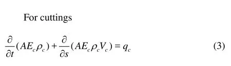
where A is the area of the annulus,Eg,Emand Ecare the volumetric fractions of the natural gas with high H2S content, the water base drilling fluid and the cuttings,ρmand ρcare the densities of the drilling mud and the cuttings,fρgand fρgcare the density functions of the natural gas with high H2S content,Ppc,Tpc,Mg,Sgare the critical pressure, the critical temperature, the molecular mass, and the supercritical factor of the natural gas with high H2S content,Vg,Vm,Vcare the velocities of the natural gas, the water base drilling fluid and the cuttings,qg,qcare the productions of the natural gas and the cuttings,qgis the released H2S, which can be calculated by the method shown in “Section 2.2.2”, and is dissolvedinthe water base drilling fluid.
1.1.2 Momentum conservation equation

where the subscript “j”(=1,2,3)means the natural gas, the drilling fluid, and the cuttings, respectively, αis the hole deviation angle,pis the annular pressure,sis the coordinate in the flow direction,g is the gravity acceleration,d Pf/dsis the friction loss.
1.1.3 Energy conservation equations
The influence of the cuttings on the heat transfer process between the formation and the fluid in the wellbore is neglected and the natural gas and the drilling fluid are the only components participating in the process of the heat transfer[6]. The energy conservation equations in the annulus and the drilling pipe are as follows:
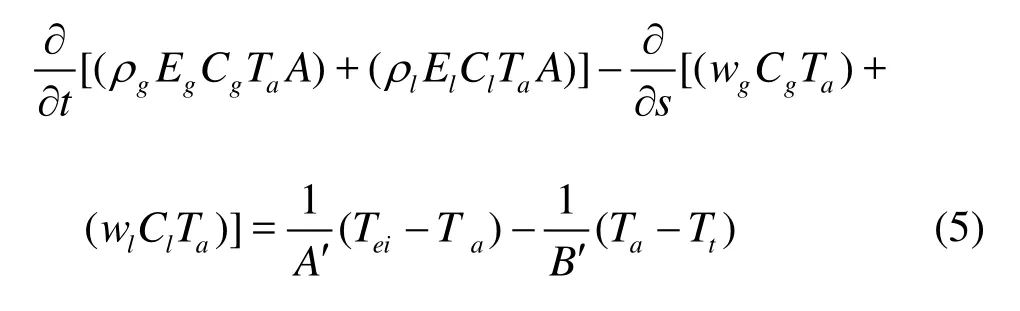
The energy conservation equations in the annulus
The energy conservation equations in the drilling pipe

where wg,wlare the mass flow rates of the gas and the liquid,Tei,Ta,Ttare the temperatures of the formation, the fluids in the annulus and the pipe,A′and B′are coefficients and can be calculated by

where keis the heat conduction coefficient of the formation,rcois the outer radius of the casing,rtiis the inner radius of the drilling pipe,TDis the initial environment temperature[9].Utis the heat transfer coefficient between the drilling fluid in the drilling pipe and the wall of the drilling pipe,Uais the total heat transfer coefficient of the annular fluid and the strata and can be calcula- ted by
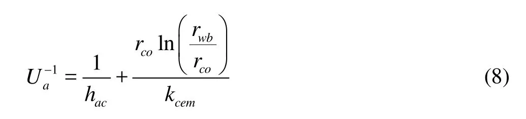
where hacis the convection heat transfer coefficient between annulus and casing,rwbis the radius of the well and kcemis the heat conductivity of cement.
1.2 Auxiliary equations
To solve the multiphase flow and heat transfer equations, some auxiliary equations are needed. They are the velocity equations, the slip velocity equations, the PVT equations of the fluids, the wellbore geometry equations, the volumetric fraction equations, the fluid viscosity equations, the friction loss equations, the formation temperature equations, etc.. The main auxiliary equations representing the natural gas properties are as follows.
1.2.1 Solubility of H2S in water base drilling fluid
The state equation is universally required to compute the solubility in the gas/liquid equilibrium state at high pressure conditions. The fugacities of H2S in the gas and liquid states are equal when the solubility of the gas is balanced in the liquid, as expressed by the following equations.

The solubility of H2S in the drilling fluid can be expressed by

With A =ap/R2T2,B =bp/RT,Z =PV /RT, Eq.(11) can be written as

wherea,bare coefficients, which can be solved by the following equations:
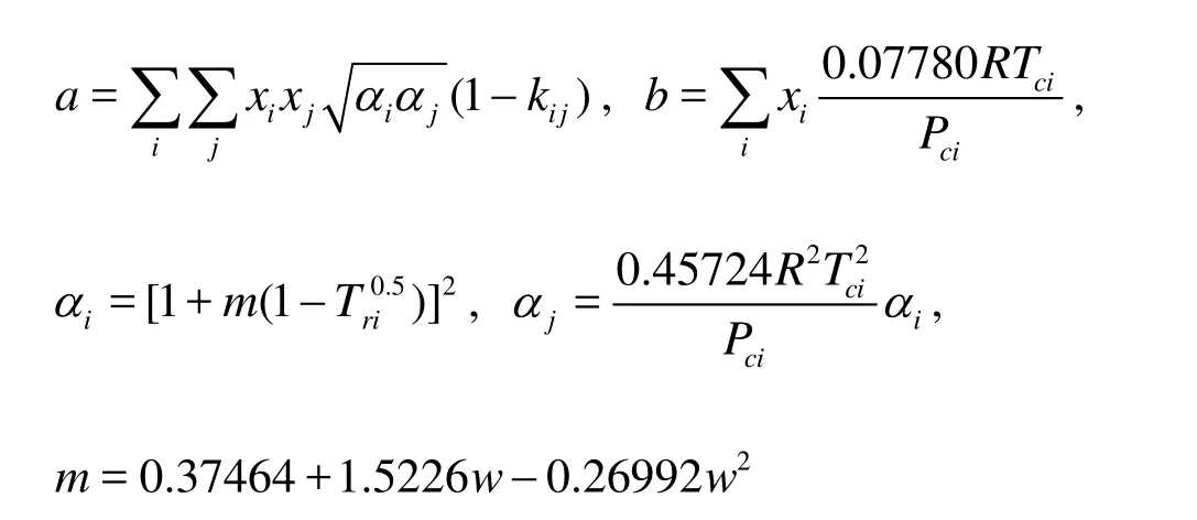
where kijis the interaction coefficient between H2S and hydrocarbon components in the natural gas,Tci, Pciare the critical temperature and pressure of H2S, Triis the correspondent temperature of H2S,wis the acentric factor of H2S.
The expression of the fugacity coefficient of a certain component is
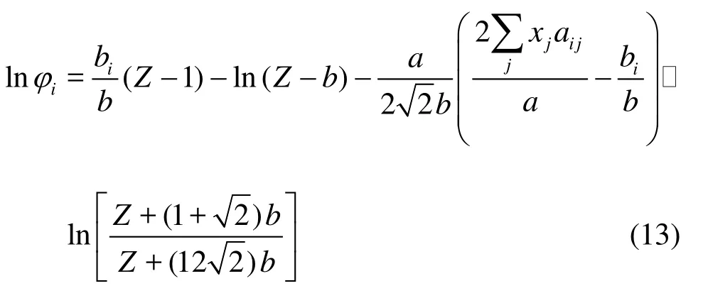
Combining Eq.(10) through Eq.(13), the solubility of H2S in the liquid can be obtained.
1.2.2 Viscosity of natural gas with high H2S content
The equations proposed by Sutton[15]is used to calculate the viscosity of the natural gas with high H2S content under high pressure:
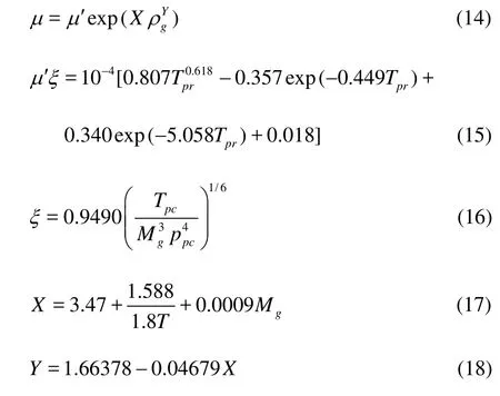
where Mgis the molecular mass of the gas,ρgis the density of the gas,Tis the temperature,Ppcis the gas critical pressure andTpcis the critical temperature of the natural gas with high H2S content, and Ppcand Tpcchange with the increase of H2S content.
1.2.3 The criterion of supercritical conditions
In the critical or supercritical flow in the wellbore, due to the high pressure in the bottom hole, it is an obvious phenomenon that the acidic gas is dissolved in the drilling fluid, involving a significant fraction of the acidic gas. When the gas is fully dissolved in the drilling fluid, the flow can be considered as the liquid-solid flow. If a part of the gas is dissolved in the drilling fluid, the flow can be a gas-liquid-solid flow. With the supercritical flow moving upward along the wellbore, a part of the supercritical gas which is originally dissolved in the fluid will be released, thus the gas component increases in the wellbore. For the supercritical state fluid, the temperature and the pressure are higher than its critical temperature and critical pressure.

where Ppcis the gas critical pressure and Tpcis the critical temperature of the natural gas with high H2S content,Sis the supercritical factor. When the gas is in the supercritical status, the gas-liquid-solid flow can be seen as a liquid-liquid-solid flow. As the above equation contains seven kinds of components, it will be called the seven-component multiphase flow model.
2. Numerical solution method
2.1 Definition conditions of energy equation
(1) Initial conditions
The flow conditions of the well bore in the drilling process will be changed by the formation fluid invasion. The initial conditions of temperature field (energy conservation equation) are the stable temperatures in the annulus and in-pipes of drilling.
(2) Boundary conditions
The temperature at the drilling pipe entrance can be measured,
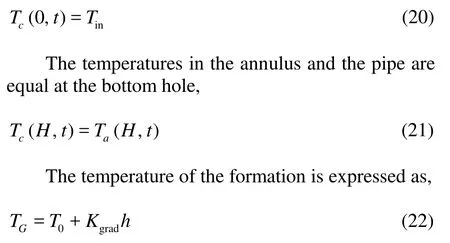
where Tinis the temperature at the drilling pipe entrance,Kgradis the geothermal gradient,His the total drilled depth,his a given position of the well bore.
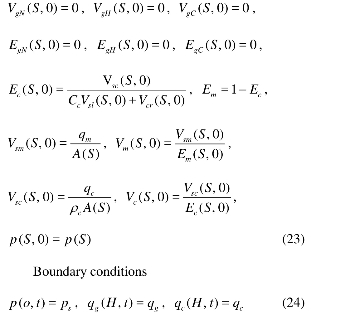
2.2 Definition conditions of flow and pressure equations
(1) Kicking period
During the kicking period, the fluid circulation is still on and the wellhead is open. The initial conditions are as follows
(2) Shut in period
Initial conditions are determined by the ending conditions of the kick process before the shut in
(3) Killing period
During the killing period, the flow is set to the half-rate and the “driller’s method” is used within the wellbore. The initial conditions are


where Qg(t)is the gas production function during the shut-in period,ppis the formation pressure,peis the killing supplementary pressure.
2.3 Solution procedure
The flow is unsteady if the fluids are produced in the drilling process. The finite difference method is used to solve the equations. The overflow dynamic process of any two nodesjand j+1in the annulus from timento n+1is taken as an example to illustrate the solving method,ΔSj=Sj+1-S,Δt= ΔSj/Vg. The solution procedure is as follows:
(1) Assuming that the pressure at node jand timen +1as pn+1(0).
j
(2) Calculate the temperature Tn+1at node j and time n+1in the annulus and the pipe by solving the energy equation.
(3) Determine the phase equilibrium of the acid gases in the well bore under the supercritical condition with the related pressure and temperature.
(4) Calculate the density, the viscosity and other physical parameters of each phase from the Equation Of State (EOS).
(5) Calculate the density, the viscosity and other physical parameters of the mixture.


3. Case study of deep well control
This calculation case is based on a real drilling project and the result can provide some guidance and reference for the industry. In order to better understand the processes of the gas kick and its killing in the wells with H2S, the multiphase flow model described above is applied to the simulation and analyzing processes. The basic parameters of the well are as follows: the calculated well depth is 4 325 m, the drilling fluid density is 1.2×10³kg/m3, the drilling fluid plastic viscosity is 30 mPa∙s, the dynamic shear force is 10 Pa, the drill string outer diameter is 0.127 m, the inner diameter is 0.1086 m, the surface temperature is 30oC, the geothermal gradient is 3oC/100 m, and the formation pressure coefficient is 1.254.

Fig.1 Density curves of natural gas with different H2S contents
3.1 The density of natural gas with different H2S content in well bore
When the gas enters the wellbore along with the travelling up of the drilling fluid, the temperature and the pressure change continuously along with the gas density. For the natural gas with high H2S content (we assume that the natural gas is composed of CH4and H2S) in the supercritical state in the down hole, the density change along the well depth is different from that of a normal hydrocarbon gas. This paper uses the density curves of the natural gas with different H2S contents as shown in Fig.1. The density of the methane reaches more than 200 kg/m³, but H2S, which is in the supercritical state, can reach 800 kg/m³, close to the liquid density. When H2S approaches the well- head, its density falls rapidly from 800 kg/m³ to less than 100 kg/m³. At the same time, the volume expands dramatically due to the change from the supercritical state to the subcritical state, with a great risk to the well control. When the acidic gas enters, with the same mass, it occupies a smaller volume than the hydrocarbon gas since its density is higher. Therefore, its detection is difficult. However, when it rises to the wellhead, the fierce volumetric expansion significa- ntly increases the risk of the blowout. Therefore, a great attention should be paid to this situation.
3.2 The variations of solubility of acid gases along wellbore
The gas compressibility factor is an important parameter to adjust the behavior deviation between the real gas and the ideal gas. The gas compressibility factor of the natural gas with different H2S contents varies in the flow process along the wellbore. The minimum gas compressibility factor of the gas with 100%-H2S is less than 0.2, while the minimum gas compressibility factor of the gas with 0%-H2S is about 0.8. As a result, the acid gas deviates more severely from the ideal gas than the normal hydrocarbon gas, and the compression degree of the acid gas in the wellbore is higher. The density is also relatively high.

Fig.2 Solubility distribution of the natural gas with different H2S contents along the wellbore
The solubility of the natural gas with different H2S contents in the wellbore is calculated by using the solubility computational equation, and the results are shown in Fig.2. In the wellbore condition, the solubility of the natural gas with 0%-H2S is very small, and its neglect would have little effect on the result of the multiphase flow calculation. Compared with the natural gas with 0%-H2S, the solubility of the natural gas with 100%-H2S are much higher, and in the well depth of 4 250 m the solubility is 0.4067, which is about 130 times higher than that of the natural gas with 0%-H2S. With the increase of the H2S content in the natural gas, the solubility of the gas also increases. Therefore, in the case of higher H2S concentration, the solubility of the gas cannot be ignored in thecomputa- tion. The solubility of H2S changes gradually when the depth is more than 600 m. However, it changes sharply approaching the wellhead.
Assuming that 0.5 m3of drilling fluid saturated with the natural gas with different H2S contents at the bottom travels up along the wellbore, and within 600 m to the top depth, the gas volume increases quickly. At the surface, the volumes of the natural gases with 100%-H2S, 20%-H2S, 10%-H2S, 5%-H2S and 0%-H2S reach the maximum values of 6.35 m³, 2.62 m³, 2.23 m³, 1.84 m³ and 0.185 m³, respectively. With the increase of H2S content, the released gas volume becomes larger as shown in Fig.3. Therefore, in the H2S rich formation, some of the gas can be dissolved into the drilling fluid after the gas invasion, which makes the well kick “invisible”. The large amount of the gas dissolved in the drilling fluid will come out near the surface, which makes the well kick a “sudden” incident. All these will make the well control difficult, and a special attention should be paid in the drilling practice.
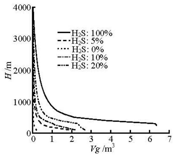
Fig.3 Volume variation of the released gas when 0.5 m3drilling fluid saturated with gas with different H2S contents at bottom travels up along the wellbore
3.3 Simulation of acidic gas expansion in wellbore
In the northeastern Sichuan area of China, the content of H2S is over 10%. Considering the supercritical characteristics of the acidic gas and its dissolution, taking the methane containing rich H2S (0%, 5% and 10%) as an example, the expansion of the gas is simulated with the invaded 0.5 m3gas at the bottom hole moving upward along the wellbore. Figure 4 shows the changes of the natural gas fractions along the wellbore with the gas ascending 35 min and 135 min to the wellhead with different contents of H2S. It is shown that the natural gas is in a supercritical state at the depth corresponding to 35 min. At this stage, the density is relatively high, and a part of the acidic gas is dissolved into the drilling fluid. There- fore, a higher H2S content corresponds to a lower gas volume fraction. However, at the instant of 135 min, the gas flows to the upper wellbore and its tempera- ture and pressure decrease. The acidic gas transits from the supercritical state to the subcritical state, and then becomes the normal gas. With this transforma- tion, the gas volume expands abruptly, at the same time, the acidic gas is released from the solution. Therefore, the volume fraction of the gas with higher H2S content is greater than that of the gas with lower H2S content.
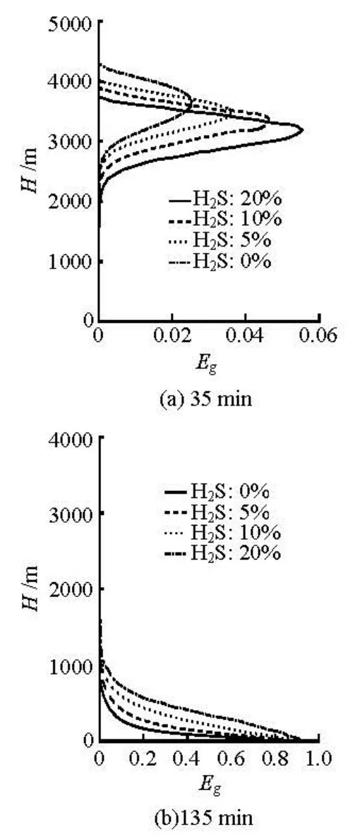
Fig.4 The gas void fraction in wellbore at 35 min after gas invasion at bottom hole with different H2S contents

Fig.5 Pit gain changes when the invaded gases move upward along the wellbore with different H2S contents
Figure 5 shows the Pit Gain (PG) changes when the invaded gases move upward along the wellbore. It also indicates that the natural gas with higher H2S content expands much more when coming very close to the wellhead. In this example, the PG with 10% H2S is 2 m3more than the PG without H2S. If the initial invaded gas volume is very high, the situation iseven worse.
3.4 The acidic gas overflow process simulation
The gas overflow process is simulated with the natural gas with different contents of H2S as examples. In all cases, the gas production index is 0.15 Nm3/(MPa∙s). Figure 6 shows the PG curve in the process of the acidic gas invasion over time. With the same gas production index, the invasion process of the acidic gas with different contents of H2S shows different features. In the initial stage of the gas invasion, the PG with lower H2S content is higher than that with higher H2S content. H2S is in the supercritical state under the HTHP condition at the bottom hole, and its density is relatively high. A smaller volume is requi- red for the same quantity of gas invasion. In addition, due to the high solubility of H2S at the bottom of a well, a part of H2S is dissolved in the drilling fluid, which makes the gas volume smaller. With the gas invasion going on for some time, the phase change eventually occurs and the supercritical H2S is transfor- med to the gas along with the return of the drilling fluid. At the same time, H2S is also released from the drilling fluid gradually, which causes a severe in- crease of the gas content in the wellbore. Therefore, the PG with higher H2S content has a larger slope than the PG with lower H2S content at the later stage of the gas invasion. For example, the increase of PG from 10 m3to 57 m3takes 28 min for the case without H2S, 21 min for the case of 5% H2S content, and only 18 min for the case of 10% H2S content. As a result, the well kick with high acidic gas content has a pote- ntial effect at the early stage and a ramping effect at the later stage.
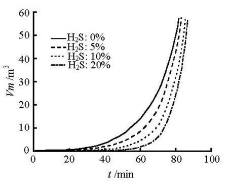
Fig.6 Pit gain changes with time with different H2S contents
The calculations of the mud pool increment, the variations of BHP and the shut-in casing pressure in the process of the acidic gas invasion all show an important feature: the invasive gas expands latently at the early stage but suddenly at the later stage. Therefore, for the drilling in layers with high acid gas content, early monitoring should be very important, and once an overflow is found, a great attention should be paid. If it is needed to cycle out the overflow, a higher back pressure at the wellhead should be maintained while ensuring the safety of the wellbore, in order to restrain the severe expansion of the acid gas.
3.5 Discussion on suppression of acid gas expansion
For the acid gas well kick may expand latently at the bottom but suddenly near the wellhead, a back pressure can be added to the wellhead while circulating out the gas invasion. Figure 7 shows the expanding changes of the 0.5 m3invasive gas while rising along the wellbore under the back pressures of 3 MPa. It can be observed that the wellhead back pressure has a significant inhibition effect on the gas expansion. The higher the back pressure is, the smaller the acidic gas expansion is in the borehole, and the smaller PG is. Therefore, while drilling in layers with high acid gas content, the back pressure can be raised up properly in the process of circulating out the gas invasion to restrain the acid gas sudden expansion, to ensure the safety of the well control.
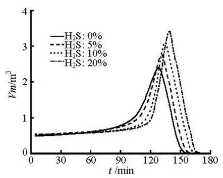
Fig.7(a) Pit gain changes with gases moving upward along wellbore with the wellhead back pressure of 3 MPa

Fig.7(b) The maximum value of pit gain at different wellhead back pressures
4. Case analysis
Using the gas kick field data of the “DW-X1H well” in Sichuan basin, where a high content of H2S is present, the proposed algorithm is validated. In the process of drilling, the mud volume is found to increase 1.9 m3. At this instant, the well depth is3 719 m, the well diameter is 0.32 m, the flow rate is 30 L/s, the drilling fluid density is 1.43×10³kg/m3, the drilling fluid viscosity is 28 mPa∙s, the drilling fluid shear stress is 12.5 Pa, and the H2S content is 17% (molar concentration). After the shut-in, the shut-in casing pressure is 2 MPa and the shut-in stand pipe pressure is about 1.9 MPa. With the throttle pressure of 2 MPa, the circulation is provided to replace the invasion gas. According to the basic data of the well, the simulation of the overflow is carried out, and the simulation results and the field data are compared, as shown in Fig.8. It can be seen that the simulation results considering the gas phase transition and the H2S solubility agree very well with the field data and the maximum simulation error is only 4.8% while the simulation error without considering the gas phase transition and the H2S solubility is 19.7%.

Fig.8 Comparisons between simulated results and field data for pit gain
5. Conclusions
In the process of deep well drilling, the natural gases with high H2S content are in the supercritical state when they invade the wellbore at the bottom hole. They go into the subcritical or gaseous state when moving up along the wellbore. The solubility of H2S component in the natural gas is high at high pressures and the dissolved gas can be released rapidly when the pressure drops near the wellhead region. Due to this behavior of the natural gas with high H2S content, the gas invasion would be in greater extent hidden in the lower wellbore, accompanied with the abrupt kick in the upper wellbore. In this study, a multiphase flow model is proposed with consideration of the phase transition and the solubility of H2S in the natural gas. A numerical methodto solve the model equations is also presented.
The simulation results indicate that, the natural gases with high H2S contents have high densities under supercritical conditions, and smaller volumes compared to the hydrocarbon gases at high pressures. The density of H2S is around 800 kg/m³ at a depth of over 500 m, and it sharply reduces to less than 2 kg/m³ from the depth of 500 m to the wellhead. The solubility of H2S has a similar trend as that of the density which means that it changes very little at the depth over 500 m and decreases sharply from the depth of 500 m to the wellhead. The solubility of H2S is 130 higher than that of methane at the depth of 4000 m. In the initial stage of the gas kick, the PG with lower H2S content is higher than the PG with higher H2S content. At a later stage of the gas kick, however, the PG with higher H2S content has a larger slope than the PG with lower H2S content due to the supercritical H2S transi- tion to the gas state and the release of the dissolved H2S from the drilling fluid. The higher the content of H2S is, the more slowly the bottom hole pressure and the shut-in casing pressure change in the early stage of the gas kick, and the more severely it declines later on. In order to eliminate the hazards to the well control caused by the abrupt expansion of the acid gases near the wellhead region, an effective practice is to in- crease the wellhead back pressure.
[1] NICKENS H. V. A dynamic computer model of a kicking well[J]. SPE Drilling Engineering,1987, 2(2): 159-173.
[2] SANTOS O. L. A. Well control operations in horizontal wells[J]. SPE Drilling Engineering, 1991, 6(1): 111- 117.
[3] NUNES J. O. L., BANNWART A. C. and RIBIRO P. R. Mathematical modeling of gas kicks in deep water scenario[C]. IADC/SPE 77253. Jakarta, Indonesia, 2002.
[4] SUN Bao-jiang, WANG Zhi-yuan and GONG Pei-bin et al.Applicationof a seven-components multiphase flow model to deepwater well control[J]. Acta Petrolei Sinica, 2011, 32(6): 1042-1049(in Chinese).
[5] WANG Zhi-yuan, SUN Bao-jiang and GAO Yong-hai et al. Simulated calculation of killing well for deepwater driller’s method[J]. Acta Petrolei Sinica, 2008, 29(5): 781-790(in Chinese).
[6] WANG Zhi-yuan, SUN Bao-jiang and GAO Yong-hai et al. Study on annular multiphase flow characteristic of gas kick during hydrate reservoir drilling[J]. Journal of Basic Science and Engineering, 2010, 18(1): 129- 140(in Chinese).
[7] WANG Zhi-yuan, SUN Bao-jiang. Annular multiphase flow behavior during deep water drilling and the effect of hydrate phase transition[J]. Petroleum Scuence, 2009, 6(1): 57-63(in Chinese).
[8] LI Xiang-fang, ZHUANG Xiang-qi and SUI Xiu-xiang et al. Study on two-phase gas-liquid flow during gas kick[J].Journal of Engineering Thermophysics, 2004, 25(1): 73-76(in Chinese).
[9] LONG Zhi-hui, WANG Zhi-ming and FAN Jun. A dynamic modeling of underbalanced drilling multiphase-flow and numerical calculation[J]. Petroleum exporation and development, 2006, 33(6): 749-753(in Chinese).
[10] ZHOU Ying-cao, GAO De-li and LIU Yong-gui. New model for calculating bottom hole pressure of multiphase flow in annulus of underbalanced straight well[J]. Acta Petrol ei Sinica, 2005, 26(2): 96-99(in Chinese).
[11] HALLMAN J. H. Fluid customization and equipment optimization enable safe and successful underbalanced drilling of high H2S horizontal wells in Saudi Arabia[C]. SPE108332. Galveston, Texas, USA, 2007.
[12] WU Q., QIAN X. and GUO Z. Probability of receptor lethality in blowout of sour gas wells[J].Petroleum ex- ploration and development,2009, 36(5): 641-645.
[13] LIU Zhen-yi, ZHANG Ying-an and QIAN Xin-ming et al. Numerical simulation on available ignition range of well blowout in sour gas field[J]. Acta Petrolei Sinica, 2009, 30(4): 621-624(in Chinese).
[14] PENG D. Y., ROBINGSON D. B.A new two-constant equation of state [J]. Industrial Engineering Chemistry Fundamentals, 1976, 15(1): 59-64.
[15] SUTTON R. P. Fundamental PVT calculations for associated and gas/condensate natural-gas systems[J]. SPE Reservoir Evaluation and Engineering, 2007, 10(3): 270-284.
10.1016/S1001-6058(13)60362-5
* Project supported by the National Natural Science Foundation of China (Grant Nos. 51034007, 51104172 and 51004113), the National Science and Technology Major Project of China (Grant No. 2011ZX05026-001), and the Program for Changjiang Scholars and Innovative Research Team in University (Grant No. IRT1086).
Biography: SUN Bao-jiang (1963-), Male, Ph. D., Professor
猜你喜欢
杂志排行

水动力学研究与进展 B辑的其它文章
- An experimental study on runup of two solitary waves on plane beaches*
- Electro-osmotic flow of a second-grade fluid in a porous microchannel subject to an AC electric field*
- Parametric instability of a liquid metal sessile drop under the action of low-frequency alternating magnetic fields*
- Influence of flow field on stability of throttled surge tanks with standpipe*
- Influence of emergent macrophyte (Phragmites australis) density on water turbulence and erosion of organic-rich sediment*
- Hydrodynamic performance of a vertical-axis tidal-current turbine with different preset angles of attack*