Hydrodynamic performance of a vertical-axis tidal-current turbine with different preset angles of attack*
2013-06-01ZHAOGuang赵广YANGRansheng杨冉升LIUYan刘艳ZHAOPengfei赵鹏飞
ZHAO Guang (赵广), YANG Ran-sheng (杨冉升), LIU Yan (刘艳), ZHAO Peng-fei (赵鹏飞)
School of Energy and Power Engineering, Dalian University of Technology, Dalian 116024,China, E-mail: zhaoguang@dlut.edu.cn
Hydrodynamic performance of a vertical-axis tidal-current turbine with different preset angles of attack*
ZHAO Guang (赵广), YANG Ran-sheng (杨冉升), LIU Yan (刘艳), ZHAO Peng-fei (赵鹏飞)
School of Energy and Power Engineering, Dalian University of Technology, Dalian 116024,China, E-mail: zhaoguang@dlut.edu.cn
(Received June 28, 2012, Revised October 23, 2012)
The instantaneous angle of attack on the blade has a significant effect on the hydrodynamic performance of a vertical-axis tidal-current turbine with straight blades. This paper investigates the influence of different preset angles of attack on the hydrodynamic performance of a three-bladed, vertical-axis, tidal-current turbine both experimentally and numerically. Experiments are carried out in a towing tank. This tested turbine’s solidity is 0.1146. The preset angles of attack on the blade are –3o, 0o, 3o, and 5o, in the experiments. Experimental results show that with the increase of the preset angle of attack from –3o, to 5o, the hydrodynamic performance of the turbine is improved significantly with the power coefficients being increased from 15.3% to 34.8%, respectively. Compared to the result of a 0opreset angle of attack, the performance of the turbine with positive preset angles of attack is experimentally demonstrated to be beneficial. This performance improvement is also shown by numerical simulations based on the Unsteady Reynolds Averaged Navier-Stokes (URANS) equations. In addition, the numerical results show that the optimal positive preset angle of attack is 7ofor the turbine studied. The corresponding power coefficient is 38%. Beyond this optimal preset angle of attack, the hydrodynamic performance of the turbine decreases. Therefore, due to the dynamic stall phenomenon, an optimal preset angle of attack exists for any vertical-axis turbine. This value should be considered in the design of a vertical-axis tidal-current turbine.
tidal-current turbine, preset angle of attack, tidal energy, numerical simulation
Introduction
With the running out of fossil fuels[1]and the environment deterioration[2], people are urgently seeking alternative energy sources, especially, renewable ones[3], such as the solar energy, the wind energy and the ocean energy. The tidal energy is, as compared to the others, predictable, relatively stable and has low visual and aural impact[4]. As a newly-developed field, the tidal-current power industry is still in its infancy.
A tidal-current turbine is a device for harnessing the energy from tidal currents and functions in a manner similar to a wind turbine. Generally, the tidalcurrent turbine can have either a horizontal or a vertical axis. Compared to horizontal-axis tidal turbines, the Vertical Axis Tidal Turbines (VATTs) can rotate in the same direction regardless of the direction of the water flow[5]. Douglas et al.[6]introduced the parameters of “SeaGen”, with a capacity of 1.2 MW. Li and Sander[7,8], Matthew et al.[9]studied the characteristics of a tidal current turbine, including its power output, the torque, the induced velocity, and the acoustic emission. They also investigated an array of tidal-current turbines including the distribution and the interaction within the turbine system. Commercialization of the tidal-current turbine is booming.
As any foil rotates for a VATT, the free-stream induces an angle of attack on the foil. Due to the rotation, the angles of attack change with the positions of the foil, varying over a wide range. According to the theory of airfoils, for any types of foils at a Reynolds number, there exists an angle of attack with the maximum lift. When the angle of attack is larger than this critical value, the lift drops sharply, which is the stall phenomenon[10]. Correspondingly, the torque generated by the turbine drops quickly as well. Due to the dynamic effects, the critical angles of attack for rotating blades are different from those obtained from a stationary state even at the same Reynolds number. Therefore, if the angle of attack can be adjusted to an optimal value for each blade at any position, the stallphenomenon can be avoided for this device and thus a good performance can be achieved.
Instantaneously adjusting the angle of attack for the VATTS is an ideal method to improve a turbine’s performance. However, additional mechanical devices are required to change the angle of attack, which might increase the structural complexity and the maintenance cost of the equipment. The most economic way is to set a proper angle of attack for each blade in advance. Rawlings[5]did a number of experiments on VATTs with different preset angles of attack. Results show that the turbines with preset angles of attack of 3oand 5oproduce a larger torque compared to those without the preset angles of attack. Hwang et al.[11]investigated the performance of “cycloidal water turbines” experimentally and numerically. A number of cases were studied with different numbers of blades, various tip speed ratios and pitch angles. Their results show that turbines with varied pitch angles perform better than those with a fixed pitch angle. Zhang et. al.[12]designed and studied a VATT with a spring-controlled, passive, varied-pitch mechanism. They investigated the influence of different turbine parameters. Results provided some guidance for the selection of turbine’s parameters and the optimization.
The above references did not provide the optimum angles of attack for the turbines studied in these papers. The current paper investigates the performance of a three-bladed vertical-axis tidal-current turbine with different preset angles of attack both experimentally and numerically in order to find the optimal preset angle of attack. Also numerical results provide information for the flow fields, which would be helpful for designing VATTS.
1. Description of experiment
All experiments were conducted in a towing tank at Dalian University of Technology. The tank is 160 m long, 7 m wide and 4 m deep and was originally designed for ship-model tests. A system was designed to adapt this facility to test tidal turbines. A support structure is fixed to the towing carriage. Therefore, the whole turbine system, held by the support structure, moves together with the towing carriage. Experiments were conducted by moving the towing carriage in still water.
The test system is shown in Fig.1, and its schematic diagram is shown in Fig.2. The whole system includes a vertical-axis turbine with three identical straight blades, a transmission system, a control system, the data acquisition equipment and the support system. The turbine was kept rotating by the motor at different speeds. The energy extracted by the turbine was recorded by a torque meter. It is convenient to obtain accurate tip-speed ratios (λ, TSR) when the whole device operates in such a way.
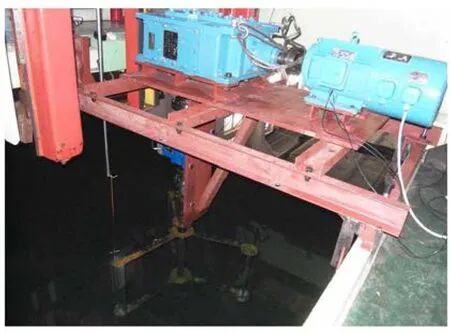
Fig.1 The experimental test system
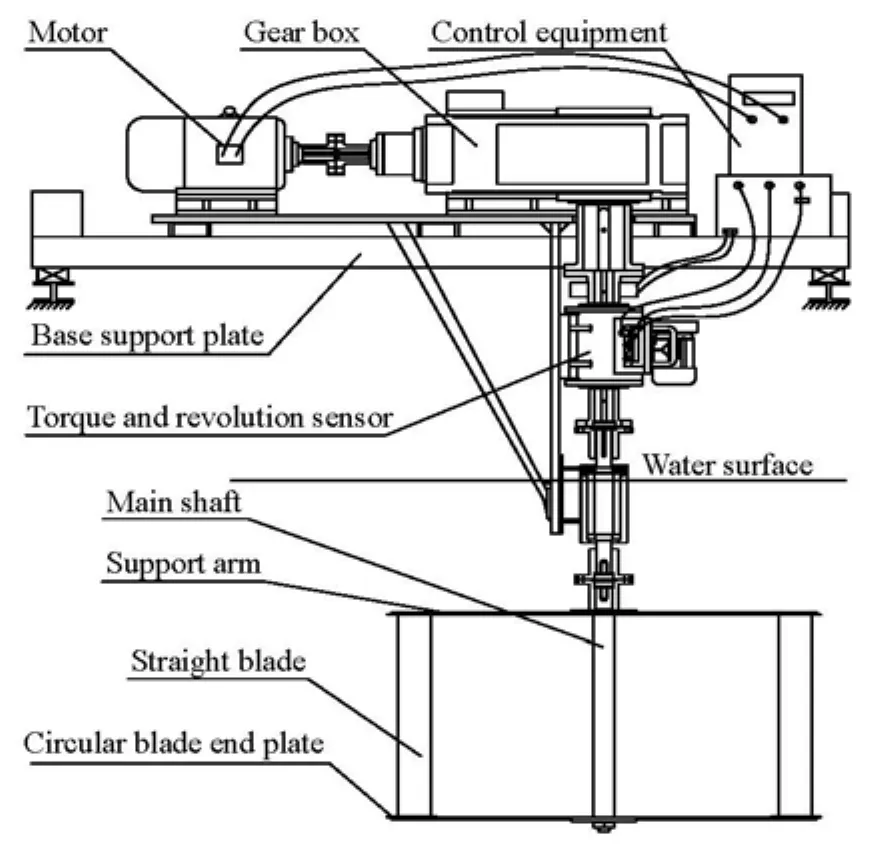
Fig.2 The turbine assembly
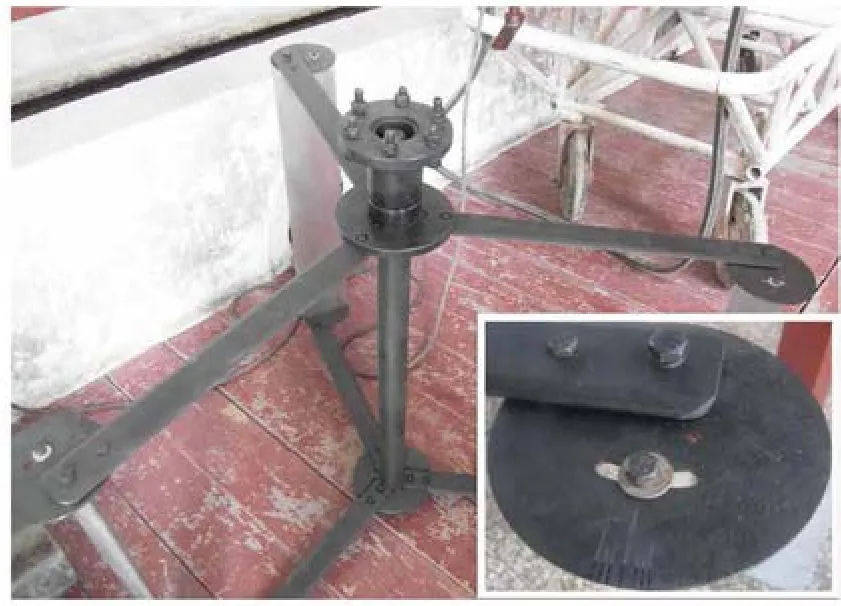
Fig.3 The photo of the three-bladed turbine with circular end plates
A circular plate is fixed on each end of every blade as shown in Fig.3. These thin plates are used to diminish the vortex loss at the blade ends[13]. Therefore, this arrangement can enhance the blade performance by decreasing the drag force[14]. Every blade is connected to the central axis by both an upper arm anda lower support arm. The circular plate and the support arm are fixed together. The blade is fixed to them by two bolts. This design provides a stable connection and a reasonable way to control the preset angle of attack on the blade. Support arms are simple rectangular solids with smoothed edges. Table 1 summarizes main parameters of the turbine.

Table 1 Parameters of the tested turbine
The experiment started with the turbine with a zero preset angle of attack at VA=1.0 m/s and VA= 1.5 m/s. The rotating speed of the turbine was kept constant by the motor during each run. For a speed of the carriage or any VA, different tip-speed ratios were achieved accurately by changing the speed of the motor. To avoid the influence of the water surface on the turbine, the upper support arms of the turbine were placed in a position of 0.5 m under the water surface. The diameter of the turbine is 1 m, while the width of the towing tank is 7 m. Therefore, no blocking effects need to be considered. For each test run, the experimental procedures are as follows:
(1) Before each test, the water surface of the tank was kept as calm as possible.
(2) The data acquisition equipment and the motor were switched on, and then the motor drove the turbine to rotate at a desired rotation speed.
(3) The carriage was accelerated up to a desired speed and kept running while the motor maintained the turbine at a desired rotation speed. Meanwhile the torque sensor recorded the instantaneous torque values when the turbine was rotating.
(4) When the recorded torque data appeared to change periodically and steadily, the data acquisition system was switched off. Then the motor and the carriage were turned off. This completed one test run.
Repeating the above procedures of (1)-(4), a number of sets of torque data were obtained for different carriage speeds and various rotation speeds. After finishing measurements for the case with zero preset angle of attack, the cases with preset angles of attack of –3o, 3oand 5owere investigated. Experimental results for different cases are given in Section 4.
2. Numerical method
2.1 Governing equations
For Newtonian incompressible fluids, the Unsteady Reynolds Averaged Navier-Stokes (URANS) equations can be written in the following tensor forms:
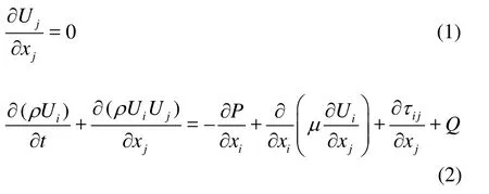
where i =1,2,3,j =1,2,3,Uand Prepresent the time averaged velocity and pressure, reospectively, µis the dynamic viscosity of water at 15C,ρrepresents the density of water,xjdenotes the spatial coordinate component,τijis the Reynolds stress, which is required to be modeled to close the above equations. For an inertial frame, the source termQ is zero, and Ujis an absolute velocity component. For a rotating frame,Qis the sum of the Coriolis and centrifugal forces, and Ujis a relative-velocity component. Here thek-εturbulence model is employed to computeτijin this study.
2.2 Computational domain
To save the computation resources and time, a half of the actual geometric model is used in thez direction (rotating axis). In addition, a turbine with a single blade is studied to obtain the performance of one blade during one cycle (360o) without influence from other blades. It should be mentioned that rectangular end plates are used instead of circular ones in the computations. This simplifies the mesh generation.

Fig.4 Computation domain with a rotational and a stationary parts
The dimension of the computational domain is 15 D×10 D ×2.5L(x×y×z )(whereDis the turbine rotor diameter, andLis the length of the blade). This computational domain is divided into two parts as shown in Fig.4. The outside part is the stationary domain, while the inside part is the rotational domain. The rotational domain is a cylinder with a diameter of 1.2D and a height ofL. This domain is computed under a rotation frame. The boundary conditions are: the inlet velocity and the outlet pressure, the wall condition for solid surfaces and other surfaces being symmetrical. A structural grid with 3 672 378 nodes of good quality was employed. The non-dimensional wall distances(y+)for the first grid nodes to the wall are between 20 and 300 for every case.
3. Results and discussions
3.1 Reynolds numbers and angles of attack
Since the energy captured by the turbine is all from the three blades, the variations of the lift force (FL)and the drag force (FD)might play a significant role. When the turbine rotates, both the attack angle(α)of the foil and the relative Reynolds numbers vary with the azimuth angle (θ). The tangential force(Ft)provides the driving force for rotation[15]. Figure 5 shows the directions of the forces anod the velocities schematically for the case ofφ=0. The relative velocity(VR)of the water is the resultant of the incoming velocity(VA)and the tangential velocity(Rω)of the water.

Fig.5 Schematic diagram of forces acting on a blade by flowing water
The static angle of attack (α)is defined as
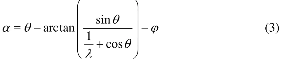
whereφis the preset angle,λ= Rω/VAis the Tip Speed Ratio (TSR) of the blade. Figure 5 shows the variation of the static local angles of attack and the relative Reynolds numbers with azimuth angles of the foil whenVA=1.5 m/s and λ=2.269 for three cases with the preset angles of attack of 0o, 3oand 5o. The definition for the relative Reynolds number(Re)is
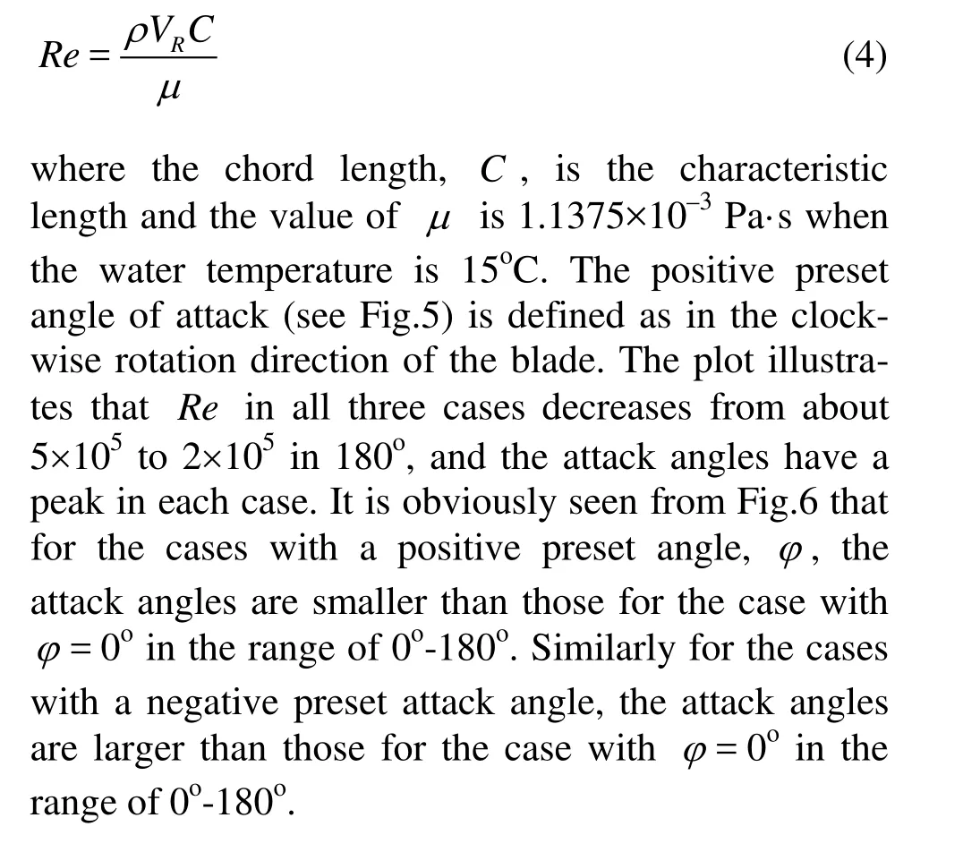
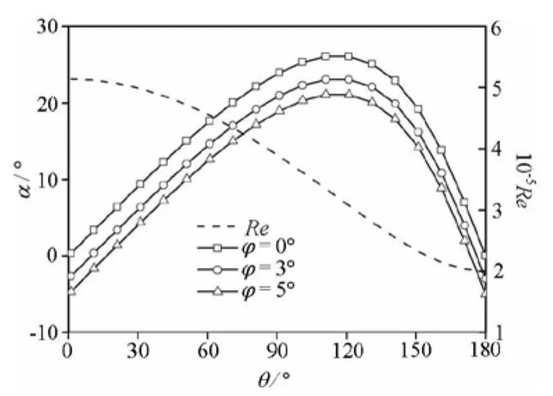
Fig.6 Variation of αand Re over 180oat λ=2.269
3.2 Experimental results
Two carriage running speeds at 1 m/s and 1.5 m/s were employed in tests. For each carriage speed, different tip speed ratios and preset angles of attack were considered. Figure 7 shows the measured power coefficient (CP)againstλat VA=1.5 m/s for four cases with different preset angles of attack.CPis calculated by using Eq.(5). There exists a maximum CPfor each case. The maximum CP(CPmax)and its corresponding optimal tip-speed ratio (λopt)for each curve are given in Table 2.
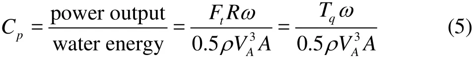
In Eq.(5),Tqrepresents the averaged torque over one revolution andAis the projected frontal area of the turbine. Here A= LD /2.
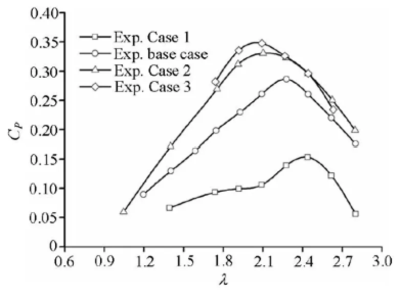
Fig.7 Measured CPagainst λat VA=1.5 m/s for the four cases
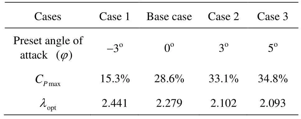
Cases Case 1 Base case Case 2 Case 3 Preset angle of attack ()φ-3o 0o 3o 5omax P C 15.3% 28.6% 33.1% 34.8% opt λ 2.441 2.279 2.102 2.093
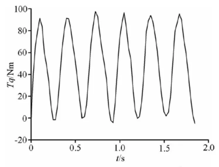
Fig.8 Variation of Tq for the case with φ=0oat λ=2.269
It can be observed from Fig.7 that the CPin all four cases increases gradually, then decreases after reaching the peak with the increase ofλ. TheCPmaxbecomes large, and its corresponding λoptdecreases with the increase of the preset angle of attack. This result can be clearly seen from Table 2. Also it can be found that the negative preset angles of attack are disadvantageous, while the positive preset angles of attack are beneficial. The reasons will be explained in Section 3.3. Therefore, when designing a VATT, it is better to preset a positive angle of attack. This can not only improve the power coefficients, but also reduce the rotating speed of the turbine. The latter feature makes the system safer and reduces the risk of cavitations.
Figure 8 shows the torque of the turbine (Tq) with φ=0oat VA=1.5 m/s and n =65 rpm,trepresents time. It has three peaks and troughs over one revolution in 0.923 s as expected.
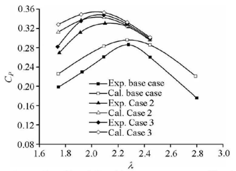
Fig.9 Comparison of predicted CPwith measurements at VA=1.5 m/s
3.3 Numerical results and discussions
Figure 9 compares the predicted CPobtained from thek-εmodel with experimental data for φ= 3oand φ=5oat VA=1.5 m/s. It can be seen from Fig.9 that the trend of the predictedCPis in a reasonable agreement with experimental data for each case. However the power coefficients of the turbine are numerically over-predicted, especially, at lowλ conditions. For small tip speed ratios, the flow separation occurs easily with large angles of attack. This flow phenomenon is difficult to be captured accurately with turbulence models. For highλconditions, the angles of attack become smaller, while the influence of the drag becomes stronger. The drag is determined by the viscous force on the surface of the blade. For any turbulence models, the viscous forces are difficult to predict accurately. These can partly explain the difference between the predicted CPand the experimental data. Moreover, without use of a transition model, a larger time step and the half domain used in the computations may contribute to some errors as well.
Figure 10 shows the streamolines of the flow field around the turbine within 120 forλ=2.269 at the symmetry plane (the middle part of the whole blade span). From this figure it can be seen that the water velocity drops and the kinetic energy is absorbed at places downstream of the turbine. Also the figure shows that the streamlines are curved and the flow is unsteady. After meeting the blades at the upstream surface, the flow is disturbed and decelerated significantly. Therefore, the divergence effect must be takeninto account in using the streamtube method to forecast the performance of the VATTs.
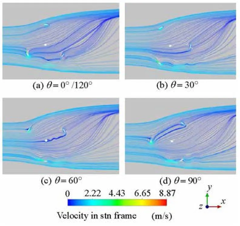
Fig.10 Streamline patterns within 120ofor λ=2.269 at the symmetry plane
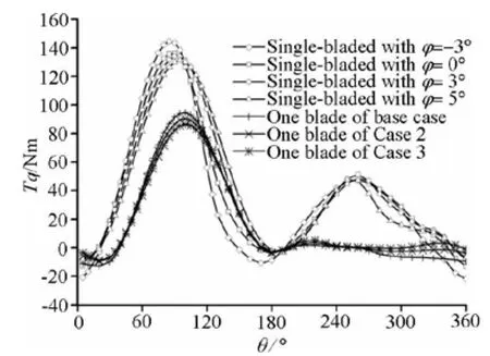
Fig.11 Variation of Tq with θin one revolution for different cases
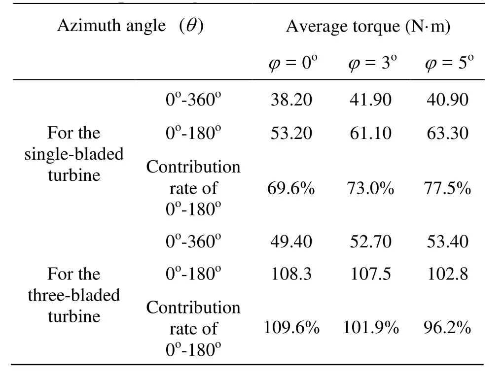
Table 3 Comparison of torque for different cases with different preset angles of attack
In order to further demonstrate the advantages of the preset angles of attack, a single-bladed turbine with preset angles of attack of 0o, 3oand 5oat VA= 1.5 m/s and n=65 rpm was studied numerically. Figure 11 shows the variation of the torque(Tq) with the azimuth angle (θ)in one revolution for the one-bladed turbine and one blade of the three-bladed turbine atVA=1.5 m/s and n=65 rpm. The figure indicates that the torque generated overθ=0oto 180o(the upstream zone) contributes most of the total output torque, especially, for the three-bladed turbine. In other words, the upstream zone affects the performance of the turbines significantly. Table 3 summarizes the average torque for one-bladed and three-bladed turbines with different preset angles of attack.
When analyzing forces acting on a blade (see Fig.5), the tangential component of the hydrodynamic force on the blade can be calculated by Eq.(6). It is the force Ftthat makes the turbine rotate. From Eq.(6), it can be found that Ftcan become larger if the lift (FL)increases and the drag (FD)decreases. Also with α being a constant, with the increase ofφ, sin(α+ φ)increases while cos(α+ φ)decreases. ConsequentlyFtcan also become greater as long as the sum of αandφis less than the stall angle ofattack. Therefore increasingφis of some benefit.
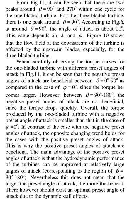

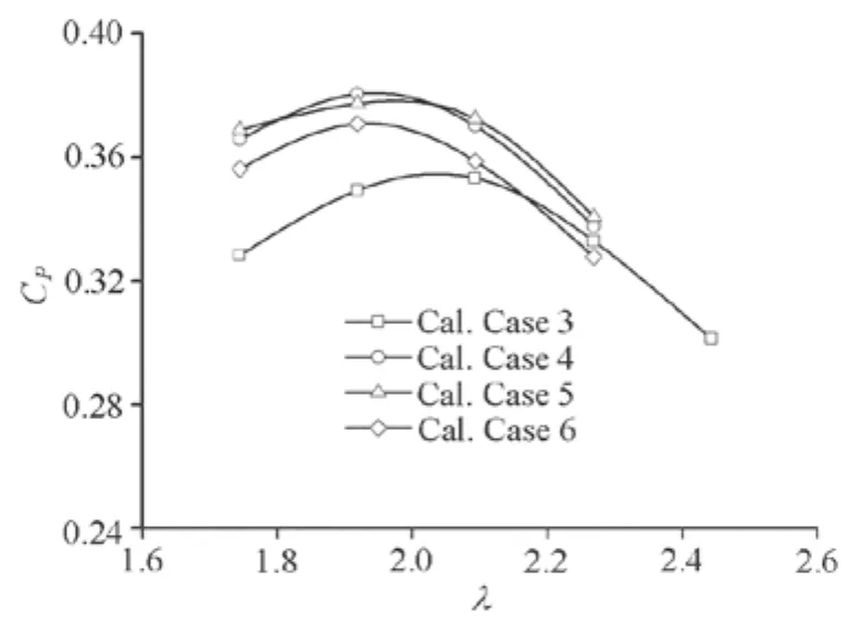
Fig.12 Comparison of predicted CPfor four cases with different φagainst λat VA=1.5 m/s
4. Conclusions
The influence of the preset angles of attack on the hydrodynamic performance of a vertical-axis tidalcurrent turbine has been investigated both experimentally and numerically. The blade profile employed is NACA0018. The experiments were carried out in a towing tank. Experimental results show that, compared to the base case with 0opreset angle of attack, the positive preset angles of attack are beneficial. The hydrodynamic performance of the turbines with positive preset angles of attack is shown to be better than turbines with negative preset angles of attack and the base case. The maximum power coefficient CPmaxare 15.3%, 28.6%, 33.1% and 34.8% for Case 1, the base case, Case 2 and Case 3, respectively. Therefore, the negative preset angles of attack are shown to be disadvantageous and the positive preset angles of attack beneficial.
Numerical results obtained from the URANS have verified the experimental findings. The following conclusions are drawn: First, the flow field at the downstream of the turbine is affected by the upstream blades. The torque contributed from the downstream zone is much smaller than that from the upstream zone. Second, the torque generated in the upstream zone becomes larger with the increase of the preset angle of attack. Therefore larger preset angles of attack help improve the hydrodynamic performance of the turbine studied. Third, due to the inevitable stall effects, there exists an optimal preset angle of attack for verticalaxis turbines. For the three-bladed turbine studied in this paper, the optimal preset angle of attack is 7o. Correspondingly the maximum power coefficient is about 38%. This value shows an increase of 33% as compared to CP=28.6% for the base case.
Acknowledgements
This work was supported by the Fundamental Research Funds for the Central Universities (Grant No. DUT13JN10) and the Doctoral Starting Up Funds of Liaoning Province (Grant No. 20111029).
[1] SHAFIEE S., TOPAL E. When will fossil fuel reserves be diminished[J]. Energy Policy, 2009, 37(1): 181-189.
[2] SOLOMON S., PLATTNER G.-K. and KNUTTI R. et al. Irreversible climate change due to carbon dioxide emissions[J]. Proceeding of the National Academy of Sciences, 2009, 106(6): 1704-1709.
[3] THEODORE R. T., LLEWELLYN J. Investors hunger for clean energy[J]. Harvard Business Review, 2007, 85(10): 38-40.
[4] LANG C. Harnessing tidal energy takes new turn[J]. IEEE Spectrum, 2003, 40(9): 13-14.
[5] RAWLINGS W. G. Parametric characterization of an experimental vertical axis hydro turbine[D]. Master Thesis, Vancouver, Canada: University of British Columbia, 2008.
[6] DOUGLAS C. A., HARRISON G. P. and CHICK J. P. Life cycle assessment of the seagen marine current turbine[J]. Proceedings of ImechE Part M: Journal of Engineering for the Maritime Environment, 2008, 222(1): 1-12.
[7] LI Y., SANDER C. S. M. Numerical analysis of the characteristics of vertical axis tidal current turbines[J]. Renewable Energy, 2010, 35(2): 435-442.
[8] LI Y., SANDER C. S. M. A discrete vortex method for simulation a stand-alone tidal-current turbine: Modeling and validation[J]. Journal of Offshore Mechanics and Arctic Engineering, 2008, 132(8): 031102.
[9] MATTHEW J. C., LI Y. and PATRICK J. M. A largeeddy simulation study of wake propagation and power production in an array of tidal-current turbines[C]. 9th European Wave and Tidal Energy Conference 2011. Southhampton, UK, 2011.
[10] WANG X. F. Marine air-hydrofoils theory[M]. Beijing, China: National Defence Industry press, 1998(in Chinese).
[11] HWANG I. S., LEE Y. H. and KIM S. J. Optimizationof cycloidal water turbine and the performance improvement by individual blade control[J]. Applied Energy, 2009, 86(9): 532-1540.
[12] ZHANG Liang, SUN Ke and LI Feng-lai et al. Hydrodynamic experimental study on new type of verticalaxis variable-pitch turbine[J]. Journal of Harbin Engineering University, 2006, 27(Suppl. 2): 346-352.
[13] GERONTAKOS P., LEE T. Effects of winglet dihedral on a tip vortex[J]. Journal of Aircraft, American Institute of Aeronautics and Astronautics, 2006, 43(1): 177-124.
[14] SOLTANI M. R., GHORBANIAN K. And NAZARINIA M. Experimental Investigation of the effect of various winglet shapes on the total pressure distribution behind a wing[C]. Proceeding of the 24th International Council of Aeronautical Sciences. Yokohama, Japan, 2004.
[15] SAEED F., PARASCHIVOIU I. and TRIFU O. et al. Inverse airfoil design method for low-speed straightbladed darrieus-type VAWT applications[J]. Wind Engineering, 2011, 35(3): 357-368.
10.1016/S1001-6058(13)60364-9
* Biography: ZHAO Guang (1981-), Male, Ph. D., Lecturer
LIU Yan, E-mail:yanliu@dlut.edu.cn
猜你喜欢
杂志排行

水动力学研究与进展 B辑的其它文章
- An experimental study on runup of two solitary waves on plane beaches*
- Electro-osmotic flow of a second-grade fluid in a porous microchannel subject to an AC electric field*
- Parametric instability of a liquid metal sessile drop under the action of low-frequency alternating magnetic fields*
- Influence of flow field on stability of throttled surge tanks with standpipe*
- Influence of emergent macrophyte (Phragmites australis) density on water turbulence and erosion of organic-rich sediment*
- Observation of the induced pressure in a hybrid micro/nano-channel*