Simulation and experimental analysis of supporting characteristics of multiple oil pad hydrostatic bearing disk*
2013-06-01ZHANGYanqin张艳芹FANLiguo范立国LIRui李锐DAIChunxi戴春喜
ZHANG Yan-qin (张艳芹), FAN Li-guo (范立国), LI Rui (李锐), DAI Chun-xi (戴春喜),
YU Xiao-dong (于晓东)
College of Mechanical and Power Engineering, Harbin University of Science and Technology, Harbin 150080, China, E-mail:yinsi1016@163.com
Simulation and experimental analysis of supporting characteristics of multiple oil pad hydrostatic bearing disk*
ZHANG Yan-qin (张艳芹), FAN Li-guo (范立国), LI Rui (李锐), DAI Chun-xi (戴春喜),
YU Xiao-dong (于晓东)
College of Mechanical and Power Engineering, Harbin University of Science and Technology, Harbin 150080, China, E-mail:yinsi1016@163.com
(Received May 20, 2012, Revised August 23, 2012)
To study the heavy hydrostatic bearing with multiple oil pads, a reasonably simplified model of the pad is put forward, and the mathematical model of the bearing characteristics of the multiple oil pad hydrostatic bearing is built with consideration of variable viscosity. The pressure field in the clearance oil film of the hydrostatic bearing at various velocities is simulated based on the Finite Volume Method (FVM) by using the software of Computational Fluid Dynamics (CFD). Some pressure experiments on the hydrostatic bearing were carried out and the results verified the rationality of the simplified model of the pad and the validity of the numerical simulation. It is concluded that the viscosity has a great influence on the pressure in the heavy hydrostatic bearing and cannot be neglected, especially, in cases of high rotating speed. The results of numerical calculations provide the internal flow states inside the bearing, which would help the design of the oil cavity structure of the bearing in engineering practice.
hydrostatic bearing, oil pad, supporting characteristics, Finite Volume Method (FVM)
Introduction
The heavy hydrostatic bearing with multiple oil pads enjoys large bearing capacity, low friction coefficient and high working stability and reliability, and is the key part of the heavy CNC equipment .The performance of the bearing directly influences the machining quality and the working efficiency of the whole equipment. With the development of the modern industry, the rotating machinery features high speed, high accuracy and large power, and the performance requirements in all aspects of the bearing becomes higher and higher. The related researches are very urgent.


The above studies were all focused on the fluid flow characteristics, but the studies of the bearing characteristics of a multiple oil pad hydrostatic bearing were few. The laboratory tests were used to analyze the lubricate performance of the gap between supporting rings in a hydrostatic bearing with multiple oil pads to determine the sector curve, and the distribution of the flow velocity and the pressure inside the hydrostatic bearing were obtained by using the finite volume method and also the temperature distributions[12-14]. This paper carries out the theoretical and experimental analyses of the bearing characteristics of a multiple oil pad hydrostatic bearing with variable viscosity, to shed light on the reliability of the heavy hydrostatic bearing.
1. The simplified model of oil pad
A special oil feeding equipment is used to lead the lubricant with a certain pressure into the static pressure cavity. The lubricant film with a certain pressure is formed to provide different pressures on the hydrostatic bearing to raise the bearing head spindle and to avoid external losses[15]. Take the constant flux oil hydrostatic bearing working element shown in Fig.1 as an example, the oil is supplied by the pump 1 and then it flows out along the radial cavity and outer annulus.

Fig.1 Constant flux oil hydrostatic bearing working elements

Fig.2 Resistive oil corners of oil pad
This element used to be simplified into two pairs of rectangular parallel plates in previous analyses of this model. The flow in the four corners could not be calculated, which will lead to a large error for the calculation of performance parameters. In order to reduce the error and increase the calculation precision, and to consider the flow in four corners, the areas of L1,L2, B1and B2and the other parameters are determined, as shown in Fig.2.
Based on the hydrodynamics and the lubrication theory, the oil pad model is simplified into two parts, the oil pad with the annular plane composed of the internal and external bilateral oil seal edges and the rectangular parallel plate with the relative movement composed of left and right bilateral oil seal edges. According to the actual fluid characteristics of the hydrostatic thrust bearing, we consider a two parallel plate flow, a ring clearance flow, as well as a truncated cone clearance flow.
2. The mathematical model of the bearing characteristics of oil film
The effective bearing area of the sector curve of the multiple pad round the guide could be simplified as a rectangular cavity in order to make calculations. The structure dimensions of the heavy hydrostatic thrust bearing, studied in this paper, are large and the maximum diameter of the machined workbench may come to 10 m. The effective bearing area is shown in Fig.3 as the shade area, where R1,R2,R3,R4,φ1and φ2are the structure dimensions of the round guide,L,l,B and bare the dimensions of the simplified rectangular cavity.

Fig.3 Effective bearing area of separate oil pad
Ae, the effective bearing area of a single oil pad, can be calculated as

The parameters shown in Fig.2,L1,L2,B1and B2are as follows:

The flow condition has a great effect on the performance as the fluid flows through the hydrostatic thrust bearing. The aim of calculating the flow field of the bearing is not only to select the rational pump but also to secure the worktable being raised through the pressure difference produced by a certain flow and the liquid resistance. Other performance formulas can also be established by calculating the flow field.
In this paper, the No. 46 Hydraulic Oil is chosen as the lubricating medium, and the numerical calculation is carried out under the condition of variable viscosity, with the viscosity-temperature relationship expressed in a power function.
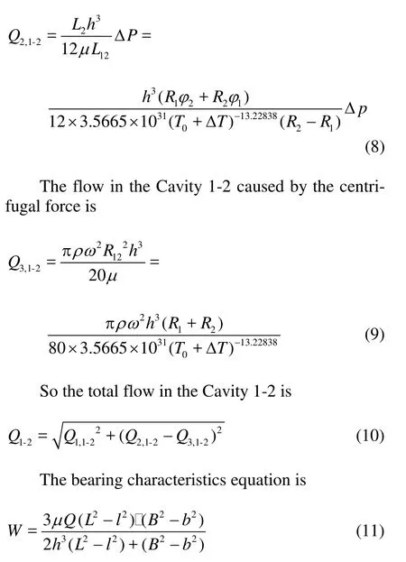
The total flow of a single oil pad is

whereQ is the total flow through the oil seal edges, Q1is the clearance flow caused by the shear stress, Q2is the clearance flow caused by the pressure difference,Q3is the clearance flow caused by the centrifugal force.Q4is the flow caused by the thermal wedge related with the pressure field and produced by the oil expansion for the temperature rise.
The influence of the thermal wedge flow can be completely ignored when the maximum cavity pressure of a single oil pad in the heavy hydrostatic thrust bearing is less than 10 MPa, and the temperature rise is over 40oC at various viscosities, that is. in the Blackburn’s theoretical condition.
Consider the oil pad. The flows through the Gaps 1-2, 3-4, 5-6 and 7-8 can be calculated as follows.
The flow in the Cavity 1-2 caused by the shear stress is

The flow in the Cavity 1-2 caused by the pressure difference is

where Q is the total flux of a single oil-pad,μis the Lubricant viscosity,his the oil film thickness, L,l,Bandb is the structure sizes of the oil-pad.

Fig.4 Boundary types
3. The numerical calculation results for the multiple oil pad hydrostatic bearing
The boundary conditions chosen in the calculation of the clearance fluid in the hydrostatic bearing are composed of the inlet boundary of the mass, the outlet boundary of the pressure, the periodic boundary, the rigid boundary, and the rotating wall boundary. Asshown in Fig.4, the geographic model field is chosen as the flow area, with the inlet and the outlet boundaries as Inner 1, Inner 2, Inner 3, Outer 1, Outer 2 and Outer 3, respectively, and the periodic boundary as Interface 1 and Interface 2. Considering only the clearance oil film, the upper surface which touches the undersurface of the worktable is the rotating wall boundary, without sliding along the grid wall.
3.2 Analysis of the numerical calculation results
The finite volume method, known as the control volume method, is adopted, whose basic idea is to mesh the calculation region and make sure that there is a mutually uncorrelated control volume around each grid point, quadrature the unknown differential equation for each control volume and obtain a set of discrete equations. Based on the selection method of the integral region, the Finite Volume Method (FVM) is the subdomain method of the weighted residual method, and from the point of view of the approximate solution method, the FVM is the discrete method by alocal approximation.

Fig.5 Pressure of oil film at 2 r/min

Fig.6 Pressure of oil film at 10 r/min
The numerical calculation conditions for the multiple oil pad hydrostatic bearing include the load of 104 t, the cavity depth of 10 m, the diameter of 0.014 m, the oil mass flow rate of 0.098 kg/s at the inlet, the rotating speed of 2 r/min, 4 r/min, 6 r/min, 8 r/min, 10 r/min, 12 r/min, 14 r/min, 16 r/min,
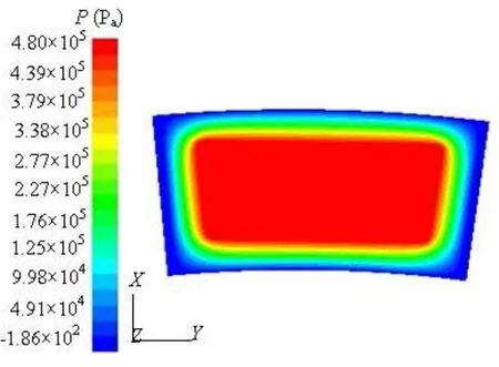
18 r/min, and 20 r/min.The results are shown in Fig.5, Fig.6 and Fig.7, respectively. By the way, only the numerical calculation results for the rotating speeds of 4 r/min,10 r/min and 16 r/min are shown in this paper, in order not to take up too much space. The calculation results under other working conditions can be deduced from the relationship curve between the clearance fluid pressure and the rotating speed.
水利部政府采购进口产品申报审批管理探析…………………………………………… 沈桑阳,郑灵芝(18.53)

Fig.7 Pressure of oil film at 20 r/min
The numerical calculation results show that the high pressure regions are distributed in the whole oil recess area when the speed is low, while the high pressure regions are distributed on the left of the oil recess at the high speed due to the hydrodynamic effect, as shown in Fig.7.
Based on the calculated results, we can obtain the relationship curve between the cavity pressure and the rotating speed, as shown in Fig.8.
It is can be seen that the pressure in the hydrostatic bearing decreases from the cavity to the seal edges, and the pressure is higher than the cavity pressure when the cavity circumferential direction is in accordance with the rotating direction of the worktable due to the dynamic pressure effect at a high rotating speed.

Fig.8 Relationship curve between the cavity pressure and the rotating speed
4. Experiments on multiple oil pad hydrostatic bearing
The oil film pressure on the heavy hydrostatic thrust bearing was measured on the DVT1000×50/ 150Q-NCdouble-pillar vertical lathe under the load of 104 t and in various rotating speeds. The hydrostatic bearing experimental equipment is shown in Fig.9.The pressure sensors are fixed on the three oil pads uniformly arranged in the circumferential direction of the annular guide of the hydrostatic bearing base.

Fig.9 hydrostatic bearing testing facility

Fig.10 Magnetic-assisted electric contact pressure gauge
The optimized magnetism electric contact pressure gauge is shown in Fig.10. The oil film pressure is measured by using the magnetism electric contact pressure gauge, with the measuring range of –0.1-0.06~2.4Mpa, with the indication accuracy of ±1.5%(FS), the setting precision of ±4%(FS), and the allowed medium working temperature of –25oC-100oC, which can meet the requirements of testing.

Fig.11 Circumferential distribution curve of film pressure in 2 r/min
The distribution curve in the circumferential direction of the oil film pressure on the hydrostatic bearing was obtained based on the experiment data and compared with that obtained from the numerical simulation and the theoretical calculation, as shown in Fig.11, where the recess pressure is used as the ordinate against the distance between the point on the single oil pad and the oil slot as abscissa.
The comparison among the theoretical calculation values, the simulation values and experimental values show that the error of the experimental results is within 3.5%, which is mainly due to the tube loss, the machining error and other aspects.
5. Conclusions
(1) In this paper, the pressure field is indirectly obtained through the finite volume method and the numerical simulation. The results are consistent and stable. Meanwhile, the pressure field agrees with the real measurements, which shows the reliability of the method.
(2) The rotating speed has a great influence on the cavity pressure. The cavity pressure becomes higher and higher by the increase of the rotating speed under condition of variable viscosity when the rotating speed is under 8 r/min.But when it is above the speed, the cavity pressure decreases greatly with the increase of the speed.
[1]HEINRICHSON N., FUERST A. and SANTOS I. F. The influence of injection pockets on the performance of tilting-pad thrust bearings[J].Journal of Tribology ASME, 2007, 129(4): 895-903.
[2]NOVIKOV E. A.,SHITIKOV I. A. andMAKSIMOV V. A. Characteristics of hydrostatic thrust bearing[J]. Khimicheskoe Neftegazovoe Mashinostroenie, 2004, 12(4): 23-26.
[3] MA Wen-qi, JIANG Ji-hai and ZHAO Ke-ding. Research on temperature rise of hydrostatic thrust bearing under variable viscosity[J]. China Mechanical Engi- neering, 2001,12(8): 953-955(in Chinese).
[4] JIANG Ji-hai, MA Wen-qi and ZHAO Ke-ding. Characteristic analysis of annular hydrostatic bearing based on variable viscosity[J]. Journal of Harbin Institute of Technology, 2000, 32(4): 19-25(in Chinese).
[5]CHEN G. H.,KANG Y. and CHANG Y. P. et al. Influences of recess geometry and restrictor dimension on flow patterns and pressure distribution of hydrostatic bearings[C]. American Society of Mechanical Engineers, Proceedings. Ann Arbor, USA, 2007, 2: 1045- 1053.
[6] SHAO Jun-peng, ZHANG Yan-qin. Numerical simulation analysis of sector and circular oil recess temperature field of heavy hydrostatic[J].Journal of Hydro- dynamics, Ser. A, 2009, 24(1): 119-123(in Chinese).
[7] ZHOU Jing-jun, YU Kai-ping and MIN Jing-xin. The comparative study of ventilated super cavity shape in water tunnel and flow field[J]. Journal of Hydrodyna- mics, 2010, 22(5): 647-655.
[8] YU Xiao-dong, MENG Xiu-li and WU Bo. Simulation research on temperature field of circular cavity hydrostatic thrust bearing[J]. Key Engineering Materials, 2010, 141-149: 419-421.
[9] YU X., MENG X. and JIANG H. Research on lubrication performance of super heavy constant flow hydrostatic thrust bearing[J]. Advanced Science Letters, 2011, 4(8-10): 2738-3741
[10] SHAO Jun-peng, ZHANG Yan-qin and LI Peng-cheng. Static flow simulation of hydrostatic bearing ellipse and sector curve based on fluent[J]. Lubrication Engineering, 2007, 32(1): 93-95(in Chinese).
[11] SHAO Jun-peng, DAI Chun-xi and ZHANG Yan-qin et al. The effect of oil cavity depth on temperature field in heavy hydrostatic thrust bearing[J]. Journal of Hydrodynamics, 2011, 123(5): 676-680.
[12] ZHANG Yan-qin, SHAO Jun-peng and NI Shi-qian. Numerical simulation of temperature field in large size hydrostatic bearing[J]. China Mechanical Engineering, 2008, 19(5): 563-565(in Chinese).
[13] ZHANG Y. Q., YU X. D. and YANG X. D. et al. Viscosity influence research on load capacity of heavy hydrostatic bearing[J]. Key Engineering Materials, 2010, 450: 63-66.
[14] ZHANG Y. Q., YANG X. D. and LI H. M. et al.. Research on influence of cavity depth on load capacity of heavy hydrostatic bearing in variable viscosity condition[J]. Advanced Materials Research, 2010, 129-131: 1181-1185.
[15] DING Zhen-qian. Design of fluid hydrostatics support[M]. Shanghai, China: Shanghai Scientific and Technological Publishings, 2004(in Chinese).
10.1016/S1001-6058(13)60358-3
* Project supported by the National Natural Science Funds for Young Scholar of China (Grant No. 51005063), the Heilongjiang Postdoctoral Science-Research Foundation (Grant LBH-Q12062) and the National Natural Science Foundation of China (Grant No. 51075106).
Biography: ZHANG Yan-qin (1981-), Female, Ph. D.,
Associate Professor
猜你喜欢
杂志排行
水动力学研究与进展 B辑的其它文章
- An experimental study on runup of two solitary waves on plane beaches*
- Electro-osmotic flow of a second-grade fluid in a porous microchannel subject to an AC electric field*
- Parametric instability of a liquid metal sessile drop under the action of low-frequency alternating magnetic fields*
- Influence of flow field on stability of throttled surge tanks with standpipe*
- Influence of emergent macrophyte (Phragmites australis) density on water turbulence and erosion of organic-rich sediment*
- Hydrodynamic performance of a vertical-axis tidal-current turbine with different preset angles of attack*
