Sewerage Force Adjustment Technology for Energy Conservation in Vacuum Sanitation Systems
2013-03-01GUOZhonghuaLIXiaoningandKAGAWAToshiharu
GUO Zhonghua, LI Xiaoning, and KAGAWA Toshiharu
1 School of Mechanical Engineering, Nanjing University of Science and Technology, Nanjing 210094, China
2 Precision and Intelligence Laboratory, Tokyo Institute of Technology, Yokohama 226-8503, Japan
1 Introduction
Sanitation is the safe and sound disposal of human excreta, including people’s approach to satisfy their primal urge. The interest in vacuum sanitation systems for excreta collection has grown in many countries over the past decade, because vacuum sanitation systems offer advantages over traditional gravity systems, including water conservation and low maintenance cost. Under special living conditions, human excreta are collected by vacuum sanitation systems and recycled through biological approaches[1–2]. As the sanitation equipment in passenger transport, the vacuum sanitation systems are installed in high-speed railways, submarines and flights[3–4].
In the new century, as the global energy crisis deepens,energy efficiency requirements are studied in the vacuum sanitation systems. What people have realized is that the energy resources must be used wisely. So far, in vacuum sanitation systems, the water consumption is reduced, but the electric or air power is consumed to generate the vacuum at the pumps or ejectors. JR Ltd. Japan uses the concept of air power (proposed by Prof. CAI, et al[5]) to calculate the energy consumption of present vacuum sanitation systems in high-speed railways[6], and the energy efficiency of the ejector is less than 30%, resulting in a large consumption of air power. In fact, a significant portion of the energy consumed by vacuum sanitation systems is wasted due to improper settings of the same propulsive force for different amount of excreta. In respect that designers of current systems did not consider the difference in energy supply to collect different amount of excreta, these systems can be improved upon through sewerage force adjustment for energy conservation. To improve the energy efficiency, this research proposes an energy conservation design in vacuum sanitation systems based on pneumatic ejector circuit.
In this new design, the sewerage force is adjusted due to the amount of excreta. The propulsive force needed to push the excreta into the vacuum tank is related to the amount of the excreta. For liquid excreta, the sewage is considered as continuous fluid, and the propulsive force is provided by the difference between the atmospheric pressure and the vacuum. When the excreta contain solid components, the black water (mixture of water and excrement) can be considered as power law fluid, where the power law flow behavior index n is 0.352 and power law consistency coefficient K isThe pressure drop along the pipe is calculated by using the empirical model of non-Newtonian fluids.
The sewerage force is adjusted by controlling the air supply to the ejector. According to the dynamic pressure response of pneumatic ejector circuit[8], the pressure change is calculated by using the air status equation and ejector flow-rate characteristic relations. The compressed air is supplied to the ejector until the pressure in the vacuum tank reaches the vacuum degree needed to collect the excreta.
As above mentioned, in this paper, the design of sewerage force adjustment is proposed for energy conservation in vacuum sanitation systems. The system components are firstly introduced in section 2, and the working process of the system is described. After that, in section 3, the mathematical model of sewerage is built and the pressure drop along the pipes is calculated additionally for black water. Then in section 4, the pressure response in vacuum tank is studied, and the proposal of variable vacuum degree is feasible by controlling the compressed air supply to the ejector. On the basis of these studies, the effect of energy conservation is verified through experiments in section 5.
2 System Components
The system is composed of water circuits, pneumatic circuits and electricity circuits, as shown in Fig. 1, where the input and output signals are dealt with by the PC.
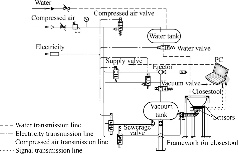
Fig. 1. Proposal for energy conservation design
The closestool has the degree of freedom in the vertical direction, and the sensors are developed to get the information of the amount of the excreta. The frameworks are made outside the closestool, supporting the load of the customers.
The pneumatic ejector circuit provides the propulsive force for sewerage. According to the amount of the excreta to be collected, the vacuum is generated, and the excreta are pushed into the vacuum tank by the difference between atmospheric pressure and the vacuum.
The experimental platform is built up in the laboratory.The closestool, vacuum tank, water tank, and storage reservoir are made of stainless steel. The electric valves are provided by SMC Ltd. Pneumatic ball valves are used as the sewerage valves at the inlet and outlet of the vacuum tank, driven by the compressed air with quick response.Fig. 2 is the photo of current experimental platform.
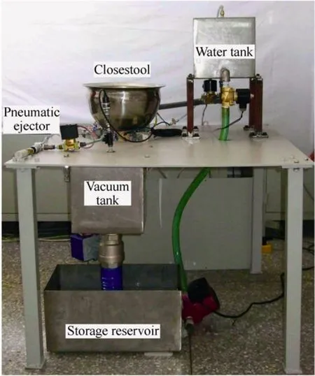
Fig. 2. Photo of the experimental platform
The working process of the system is described in detail in Fig. 3.
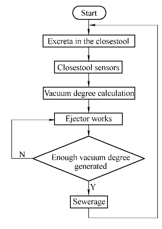
Fig. 3. System flow chart
When the system starts to work, the customer uses the closestool and flushes the closestool with a little water. The amount of excreta is measured by the closestool sensors and the vacuum degree needed to collect such amount of excreta is calculated. After that, the ejector generates the vacuum. Then the sewerage valve opens and the excreta are pushed into the vacuum tank by the propulsive force. The excreta are collected in the vacuum tank and released to the storage reservoir for further biological treatments.
3 Mathematic Model of Sewerage
What we desire is an intelligent closestool which is capable of testing the amount of the excreta and supplying the proper propulsive force for sewerage. In order to achieve this goal, we have to propose a new design for the closestool, and study the relationship between the excreta amount and the propulsive force, on the basis of the principle of sewerage.
3.1 Principle of sewerage
The mathematic model of sewerage is simplified in Fig.4, where the excreta are pushed from the closestool into the vacuum tank.aA is the area that the atmospheric pressure ap acts on; pcais the average pressure in the vacuum tank and Acais the outlet area of the vacuum tank; mwis the mass of the excreta. The Bernoulli equation is expressed as follows:
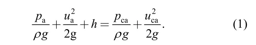
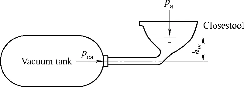
Fig. 4. Principle of air-force sewerage
The average pressure in the vacuum tank pcais below the atmospheric pressure, and the sewage begins to flow into the vacuum tank. When the excreta are collected in the vacuum tank, the pressure in the tank pcaincreases. After the sewerage process is accomplished, the pressure pcais equal to the atmospheric pressure.
3.2 Closestool sensors
Sensors are designed to measure the amount of the excreta. For liquid excreta, the sewage level sensor is developed to obtain the volume of the excreta. When there are also solid components in the excreta, the mass sensor is designed additionally to measure the mass of the excreta.
The designed sensors are shown in Fig. 5, including the sewage level sensor and the mass sensor.
The liquid level is measured by using Pascal’s Law. As shown in Fig. 6(a), a small air chamber is installed at the bottom of the closestool. When there is liquid inside the closestool, the average air pressure in the chamber pcis expressed as
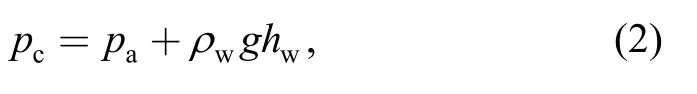
wherewρ is the density of the sewage andwh is the liquid level. By measuring the pressure pc, the liquid levelis obtained.
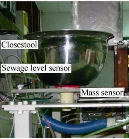
Fig. 5. Photo of sensors installed at the closestool
The mass sensor is composed of cantilever beam, strain gauges and electric circuit (Fig. 6(b)). The strain gauges are arranged as Wheatstone bridge, where the mass change is obtained from the output electric signal.
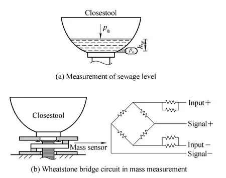
Fig. 6. Schematic diagrams of the sensors
3.3 Calculation of sewerage force
For the first step, suppose the excreta are liquid, and the pressure change in the vacuum tank is calculated. When the excreta are collected into the vacuum tank, the average pressure in the vacuum tank pcarises until it is the atmospheric pressure. The air status equation is described as
where Vcais the volume of the air in the vacuum tank;is the mass of the air; R is the gas constant,R= 28 7 N · m/( kg · K).
The air volume in the vacuum tank changes according to the volumetric flow rate of the liquid:
where Cdis the flow-rate coefficient of the sewerage valve at the inlet of vacuum tank, and Δpvalis the pressure difference in the sewerage valve.
For the convenience in the engineering, the pressure is expressed as the vacuum degree pv:
Supposing that the temperature in the vacuum tankcaθ is the room temperature aθ, the pressure change during the sewerage process is derived from Eqs. (3)–(5). When the volume of the excreta iswV and the vacuum degree is pv,the volume of collected excreta is equal to the change of the air volume. When all of the excreta are collected, the volume of the total excreta Vwis equal to the change of the air volume aVΔ , and the system provides the minimum propulsive force for sewerage.
Experiments are carried out by using water to simulate the liquid flow in this sewerage system. Different volumes of water are supplied into the closestool. When the volume of the water is 0.5×1 0−3m3, for example, the vacuum degree pvvaries from 0 to 60 kPa. At each vacuum degree, the water is collected in the vacuum tank until the pressure in the tank is the atmospheric pressure. The amount of the residual water in the closestool is measured,and the collection ratio ϕ is defined as the ratio of collected water to the total water. In Fig. 7, the volume of water varies from 0.5 × 10⁻³m3to 1.5 × 10⁻³m3. The dash lines represent the calculation results derived from Eqs.(3)–(5).
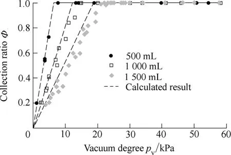
Fig. 7. Relation between vacuum degree and collection ratio
From Fig. 7, it can be seen that the experimental data agree with the calculation result, where the maximum difference in the collection ratio is approximately 10%.Because there is friction loss along the pipes, the vacuum degree needed in sewerage operations is higher than the calculated result. Take the experiment of 1 500 mL as an example. The collection ratio ϕ is 100% when the vacuum degree is set as 22 kPa. However, this value in the calculation is only 18 kPa. Therefore, the vacuum degree should be set as 25% higher than the calculation value. For human excreta which vary from 0.2 × 10⁻³m3to 1.6 × 10⁻³m3, the vacuum degree pvis to be set as 150%of the calculation value.
When the excreta contain solid components, the black water (mixture of water and excrement) or sewage sludge belongs to the class of power law fluid[9]and is transported through a pipe to disposal sites. The pressure drop along the pipe is calculated by using the empirical model of non-Newtonian fluids, and higher vacuum degree is required to accomplish the sewerage operation. According to the power law fluid theory, the pressure drop along the pipe ΔLp is calculated as follows:
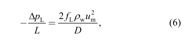
where umis the average sewage velocity; L is the length of the pipe, and D is the inner diameter of the pipe. For laminar flow where Reynolds number Re is less than 2 000,the friction coefficient fLis as follows:
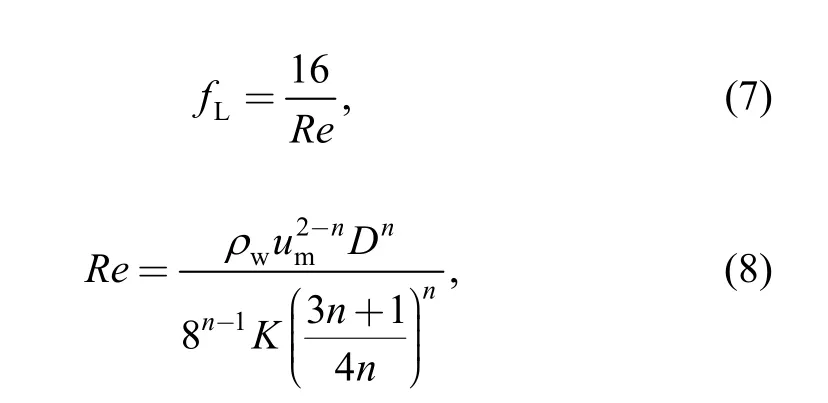
where n is power law flow behavior index and K is power law consistency coefficient.
When the black water is flowing into the vacuum tank,the pressure in the vacuum tank changes over time and the sewerage flow rate is related with the vacuum degree in such tank. In current study, the sewerage time tmis estimated when the same amount of water is pushed by the propulsive force of pressure difference (by Eqs. (3)–(5)),and the average sewerage velocity umis calculated as
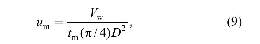
wherewV is the volume of excreta; tmis the sewerage time; and D is inner diameter of the sewer pipe.
Considering the pressure drop, the vacuum degree for black water is higher than the liquid excreta, and calculated as the following expression:
4 Sewerage Force Adjustment
According to the mathematic model of sewerage, the propulsive force for sewerage is provided by the difference between the atmospheric pressure behind the sewage and the vacuum ahead. When the vacuum degree is variable, the different propulsive force is obtained. Therefore, it is essential to provide variable vacuum degree for propulsive force adjustment.
4.1 Realization of variable vacuum degree
By controlling the time when the compressed air is supplied to the ejector, variable vacuum degree can be obtained. As shown in Fig. 8, when the ejector starts to generate the vacuum, the vacuum degree increases according to the dynamic pressure response in the vacuum tank. If the system needs the vacuum degree of 58 kPa for sewerage, the required vacuum degree is generated at time st, and the compressed air supply is cut off. The vacuum degree remains for a second by using the single direction valve. Then at time1t, the sewerage valve opens and the excreta are pushed into the vacuum tank. At time t2, the pressure in the vacuum tank goes back to the atmospheric pressure and the sewerage process is accomplished.
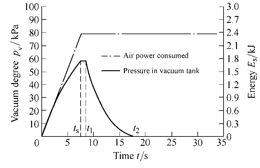
Fig. 8. Pressure change and power consumption during sewerage process
The energy consumption at the ejector is calculated as Eq.(11), wheresp is supplied air pressure,sG is supplied air flow rate and tsis the time when the compressed air is supplied[10].
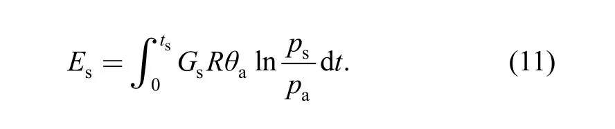
It can be obtained from Eq. (11) that when the supply pressure is ps, for the same ejector, the energy consumption is proportional to the time when the compressed air is supplied to the ejector. The higher vacuum degree is not always essential and the energy can be saved when the amount of the excreta is comparatively small.
Graphics in Fig. 8 also show that, air power is consumed when the vacuum is generated. It is noticed that, in the period from time tsto time t2, there is no power consumption at the ejector. Therefore, the power consumption during the sewerage process is decided by the air supply time. Precise calculation of the air supply time is important, not only to provide enough vacuum degree for the sewerage system, but also for minimum power consumption.
4.2 Pressure response simulation
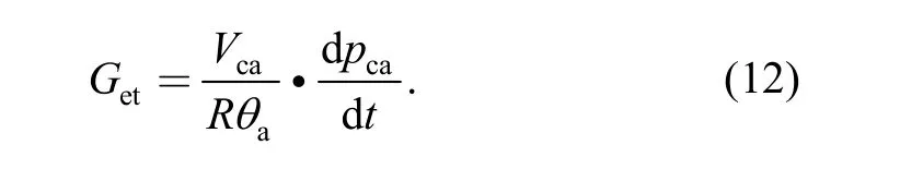
To calculate the air supply time ts, the pressure change in the vacuum tank is to be simulated by using the static flow-rate characteristics of the ejector and the differential form of the ideal gas equation. In this research, the static flow-rate characteristics are obtained by the experimental approach of isothermal discharge method[11–13]. The experimental apparatus are shown in Fig. 9(a). The temperature change is less than 3 K during the suction process, and the suction flow rate Getis calculated as
Ejectors of VCH15 and VCL15 from PISCO Ltd. are tested by the isothermal discharge method. The pressure pcais measured by high-precision pressure sensor AP-10S(Keyence Ltd.). The measured flow rates are displayed as a function of pressure at the vacuum port of the ejector, as shown in Fig. 9(b), where Getis the suction flow rate, and petis the pressure at the vacuum port.
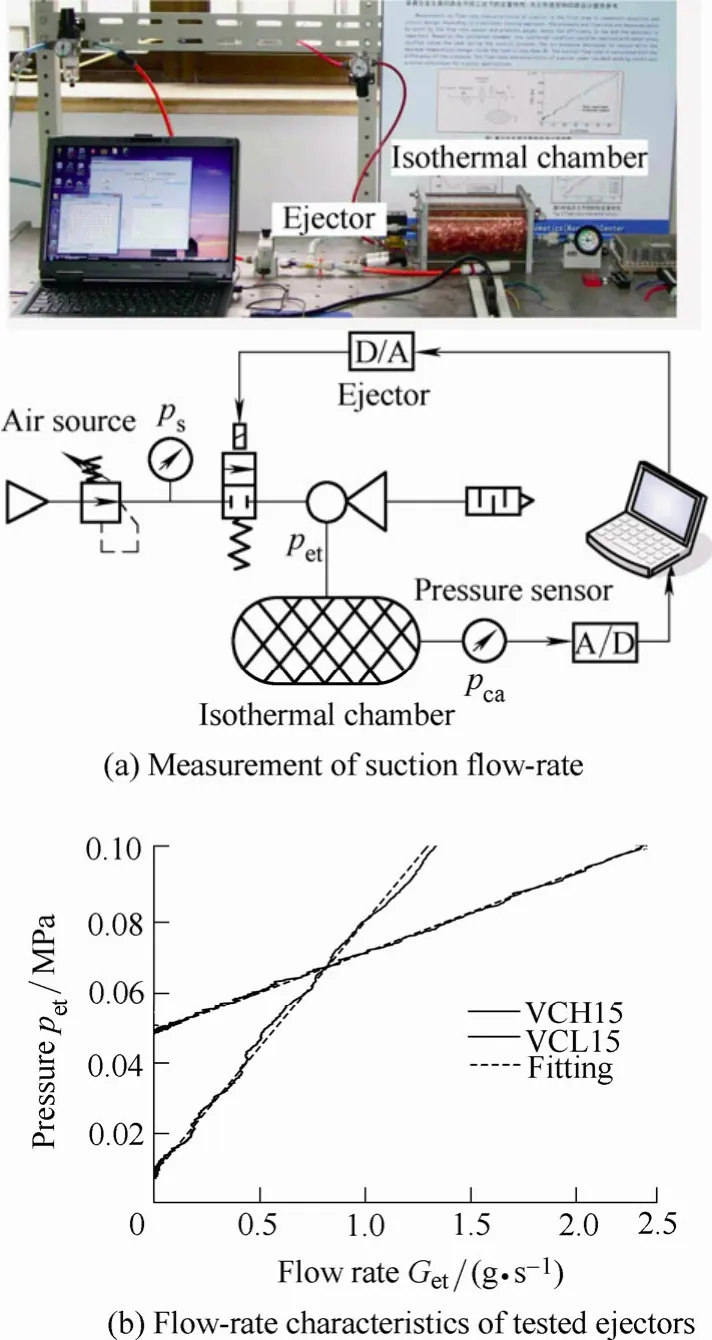
Fig. 9. Flow-rate characteristics of ejector
In Fig. 9(b), linear fitting of the experimental data is also presented and the correlation coefficient is 0.99. Ketandare the flow-rate characteristic parameters for ejectors:
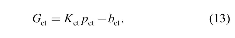
By using Eq. (13) and differential form of ideal gas equation as Eq. (3), the pressure change in the vacuum tank during the vacuum generation process is calculated.
The calculation result is plotted in Fig. 10. For the convenience in the engineering, the pressure is expressed as the vacuum degree pv(Eq. (5)). As shown in Fig. 10, this calculation approach simulates the real pressure change in the vacuum tank. Therefore, each vacuum degree can be obtained by controlling the air supply in the calculated pressure response time ts. For example, when the system needs vacuum degree pvof 58 kPa, pressure response time tsis 7.5 s according to this vacuum degree, and the compressed air is supplied to the ejector as long as 7.5 s.
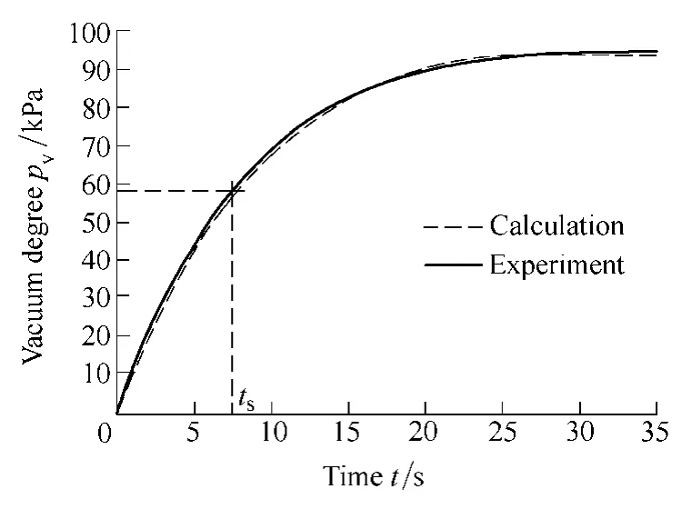
Fig. 10. Pressure response in vacuum tank
5 Effect of Energy Conservation
To verify the effect of energy conservation, experiments are carried out by using artificial excreta. Water is used for liquid excreta. For excreta of black water, approximately 30% of the black water is the artificial excrement which is made of sawdust and starch[14]. The ejector is VCH15 of PISCO Ltd, where the supplied air pressure is 0.5 MPa.The compressed air supply valve of the ejector is VT317(SMC Ltd.) and the vacuum valve in the vacuum circuit is VX2240 (SMC Ltd.). The pneumatic ball valves at the inlet and outlet of the vacuum tank are bought from Huaxing(Shanghai) Ltd. The volume of the vacuum tank is 8 × 10⁻³m3. For the pipe that connects the closestool and the vacuum tank, the inner diameter of the pipe is 30 mm,and the length of the pipe is 0.46 m.
The amounts of artificial excreta in the experiment are tabulated in Table 1. As the density of liquid excreta is different from the liquid-solid mixing excreta, the excreta type is differentiated by using the information of excreta volume and mass. The vacuum degree is then adjusted due to the amount of the excreta by controlling the air supply in the system. The vacuum degree pvis set as 150% of the calculation value derived from Eqs. (3)–(10). In the experiments, the volume of residual liquid and the mass of residual solid in the closestool are measured. The sewerage is accomplished well and the collection ratio φ is larger than 95% in current experiments.
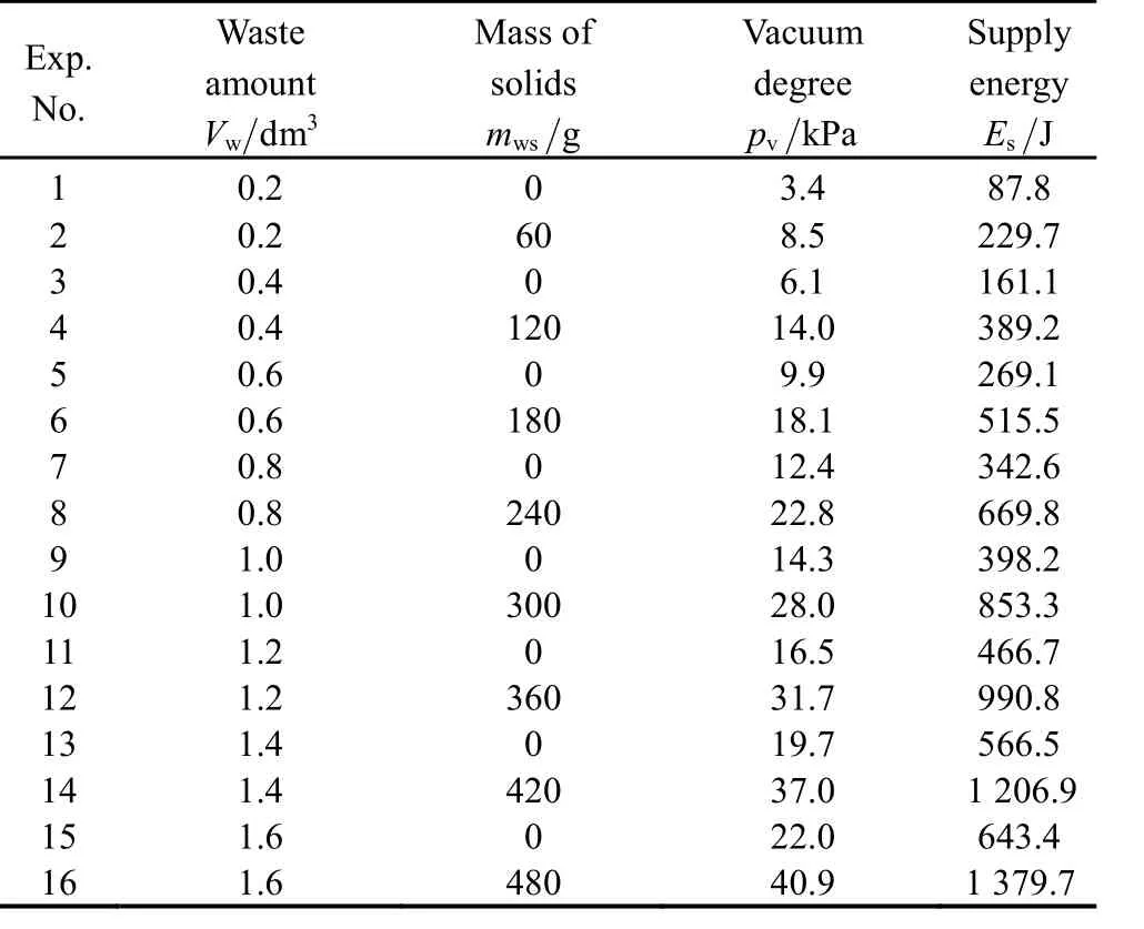
Table 1. Effect of energy conservation
The consumed air powersE is calculated as Eq. (11).When the volume of artificial excreta varies from 0.2 × 10⁻³m3to 1.6 × 10⁻³m3, the vacuum degree varies from 4 kPa to 40 kPa, and the energy consumption changes from 87 J to 1 379 J. Fig. 11 shows the vacuum degree and energy consumption when the amount of excreta is different. It can be seen from Fig. 11(a) that the vacuum degree increases as the amount of excreta is larger. When the excreta contain the solids, there is an increment in the required vacuum degree. Fig. 11(b) shows that the energy consumption changes along with the vacuum degree. More power is consumed when the vacuum degree is higher.
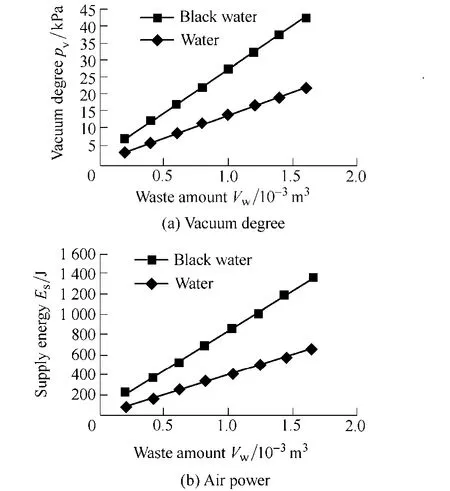
Fig. 11. Energy consumption for different amount of excreta
In respect that the vacuum degree is a fixed value of approximately 60 kPa in the conventional vacuum sanitation system[15], the energy consumption in the conventional systemis up to 2 475 J when the vacuum degree is the same during the working process. The variable vacuum- degree design saves more than 30% of the energy supply in the operation of artificial excreta collection.
6 Conclusions
(1) A variable sewerage-force design is proposed for energy conservation. This new design is based on pneumatic ejector circuit, where the sewerage force is variable due to the amount of excreta.
(2) The closestool of this new device is specially designed to have the ability of testing the amount of excreta.The vacuum degree is chosen automatically due to the amount of excreta. The vacuum degree is then adjusted by controlling the compressed-air supply according to the dynamic pressure response of pneumatic ejector circuit. In the case of fewer excreta, lower vacuum degree is generated, resulting in energy conservation.
(3) To verify the effect of energy conservation,experiments are carried out by using artificial excreta. Due to the experimental results, the variable vacuum-degree design saves more than 30% of the energy supply in the operation of artificial excreta collection.
[1] KELEMAN M. Economics of wastewater treatment codigestion[C]//Proceedings of the 4th International Conference on Energy Sustainability, ES, Phoenix, Arizona, USA, May 17–22, 2010:595–608.
[2] JENSSEN P, HEYERDAHL P, WARMER W, et al. Local recycling of wastewater and wet organic waste, a step towards the zero emission community[C]//Proceedings of 8th International Conference on Environmental Science and Technology, Lemnos,Greece, Sep. 8–10, 2003: 357–364.
[3] TENG Honghua. Pneumatic system design of vacuum water-saving toilet in the train[J]. Chinese Hydraulics & Pneumatics, 2006(3):55–57.
[4] FLERI E, GALLIANO P, HARRISON M. Proposal for a zero-gravity toilet facility for the space station[R]. National Aeronautics and Space Administration, U.S.: NASA-CR-183151.
[5] CAI Maolin, KAWASHIMA K, KAGAWA T. Power assessment of flowing compressed air[J]. ASME Journal of Fluids Engineering,2006, 128(3): 402–405.
[6] FUJINO K, TANIGUCHI K, YAMAMOTO N. Study on pneumatic supply system in Shinkansen railway vehicle[J]. Journal of the Japan Fluid Power System Society, 2010, 41(5): 92–97.
[7] DUAN Jinming, ZHOU Jingxuan. Studies on frictional pressure drop of gas-non-Newtonian fluid two-phase flow in vacuum sewers[J]. Civil Engineering and Environmental Systems, 2006,23(1): 1–10.
[8] GUO Zhonghua, LI Xin, LI Xiaoning, et al. Study on pressure response of ejector vacuum circuit[J]. International Journal of Fluid Power, 2011, 12(1): 51–58.
[9] CHHABRA R, RICHARDSON J. Non-newtonian flow in the process industries[M]. Oxford, UK: Butterworth-Heinemann, 1999.
[10] CAI Maolin, KAGAWA T. Energy consumption assessment and energy loss analysis in pneumatic system[J]. Chinese Journal of Mechanical Engineering, 2007, 43(9): 69–74. (in Chinese)
[11] ONEYAMA N, FAN Wei, ZHANG Hongli, et al. Flow rate characteristics measurement of regulators based on the pressure response in an isothermal tank[J]. Chinese Journal of Mechanical Engineering, 2009, 22(5): 633–638.
[12] KAWASHIMA K, KAGAWA T. Unsteady flow generator for gases using isothermal chamber[J]. Measurement, 2003, 33(4): 333–340.
[13] KAWASHIMA K, ISHII Y, FUNAKI T, et al. Determination of flow rate characteristics of pneumatic solenoid valves using an isothermal chamber[J]. ASME Journal of Fluid Engineering, 2004,126(3): 273–279.
[14] GB/T18092-2000, Water-free sanitary toilet[S]. National Standards of the People's Republic of China, 2000: 11–12.
[15] LI Min, ZHOU Jingxuan, WEN Xingsuo. Gas-liquid ratio and its relationship with energy consumption in vacuum sewerage system[J]. Water and Wastewater Engineering, 2010, 36(12): 69–72.
杂志排行

Chinese Journal of Mechanical Engineering的其它文章
- Metamorphic Manipulating Mechanism Design for MCCB Using Index Reduced Iteration
- High Efficient Methods of Content-based 3D Model Retrieval
- Innovative Group-Decoupling Design of a Segment Erector Based on GF Set Theory
- Simulation Research on the Effect of Cooled EGR, Supercharging and Compression Ratio on Downsized SI Engine Knock