Innovative Group-Decoupling Design of a Segment Erector Based on GF Set Theory
2013-03-01GUOWentaoGUOWeizhongGAOFengandMOPinxi
GUO Wentao, GUO Weizhong, GAO Feng, and MO Pinxi
State Key Laboratory of Mechanical Systems and Vibration, Shanghai Jiao Tong University, Shanghai 200240, China
1 Introduction
With the fast developing and modernizing of Chinese cities, the shield tunneling method has a widespread application in the development of underground transportation in the cities[1]. The shield tunneling method has the advantages of high reliability, rapid construction,high automation, and little influence to surroundings[2–3].The shield tunneling method mainly involves one kind of machine, the shield machine, integrated of excavating system, protecting shield, thrusting system, segment erector and the dragging-out system[4].
The segment erector is one of the key systems of the shield machine. It holds, transports and locates the concrete segments to construct the final inner wall structure of the tunnel, by erecting segments to a precise position to form rings along the tunnel. In segmental linings, three kinds of motions are necessary for translation, gyration and elevation. These motions need to be precisely engineered,to ensure the impermeability, the resistance and the longevity of the tunnel[5]. In order to improve quality and efficiency of segmental linings, automatic segment erectors,applying 6-DOF movements with three more motions of orientation minute adjustment, have been developed[6].
Japan is one of the earliest countries who applied automatic segment erectors in tunnel linings. The typical Japanese segment erectors, produced by Kawasaki, Hitachi,or other companies, are built for small or middle diameter tunnel[7]. These erectors usually apply the single elevation arm mechanism to form a series configuration. The typical American and Germany segment erectors, invented by Robbins, Herrenknecht, consisting of symmetric twin elevation arm positioning in a series configuration, are built for large diameter tunnel. And all of the mainstream segment erectors shared the similar structures consisting of translation, gyration, lifting and orientation adjusting mechanisms. While each mechanism works independently,the whole erector becomes a serial configuration.
Currently, Chinese cities have urgent needs for shield machines due to a large number of subway systems to be built. However, the available segment erectors have some shortcomings[8]. For example, a ring segment erector with the double lifting arm is presented by ZHANG, el at[9], but it only has 4-DOF which is not able to meet the requirement of automatic lining. A 6-DOF segment erector is presented by SHI, el at[10], forming a series configuration,but it may has insufficient rigidity and is easier influenced by accumulative errors. In a word, a segment erector of series configuration has some disadvantages, such as low rigidity and accuracy, incapacity of bracing heavier segments in large diameter (over 6 meters) tunnel.
Hence, a new type segment erector is developed in our lab using an innovative design method, so-called motion group-decoupling method. The kinematic modeling and performance analysis, numerical simulation and prototype experiment are performed in this paper to investigate the features of the new design such as reducibility and non-singularity.
2 Group-Decoupling Type Synthesis of Segment Erector
Segment erector plays vital role in the shield machine.The quality of segmental lining directly affects the infiltration of underground water and the surface subsidence. And the speed of erecting also influences the progress of the tunnel construction tremendously.Accelerating segmental lining can efficiently expedite the construction progress, which may not only save the construction time but also economize the building cost massively[11].
2.1 Task description and task decomposition of the segment erector
The segments are arc-shaped precast concrete blocks,Fig. 1 shows a typical entire ring of segments which forms a section of tunnel support. The process of one entire ring segments erecting is demonstrated in Fig. 2. The first step is transporting a segment into the tunnel. After arriving, it will be caught and then located to its own position in the ring. When a segment is correctly placed, it will be fixed by the screws between the segments joint parts. And then, the thrust cylinders will brace the fixed segments that are getting ready to drive forward. After one entire ring of segments being erected properly, the segment erector will drive forward and set the scene for the erecting of the next ring[5].
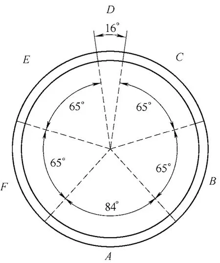
Fig. 1. Installed position of the segment
There are three basic motions of segment erector:translating along the direction of thrusting, gyrating about the thrusting axis, and picking or putting segments along the working section radius. However, automatic erecting requires the erector possessing three more dimensions of motion to adjust the orientation of segments[12].Consequently, a total of 6-DOF segment erector is proposed for automatic erecting.
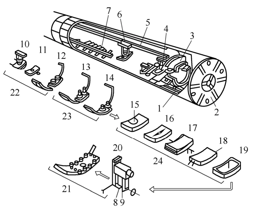
Fig. 2. Whole process of segment lining
It is crucial to stress that not all 6 dimensions of motion work the same. There are actually 3 macro motions(marked with big arrows in the figure below) and 3 micro motions in this specific case, as shown in Fig. 3. The macro or micro motions are defined according to the amplitude of motion. If a motion scale is 10% of another motion’s, then this motion is a micro motion comparing to the macro one.In this case, the 3 macro motions are moving along the direction of marching, rotating about the marching axis,picking & putting segments along the working section radius. While the 3 micro motions are minute rolling,pitching and yawing of segmental orientation. The fact that the magnitude of orientation adjustment angles are within 5 degree which is much smaller than 10% of the gyration angles, makes the orientation adjustment become micro motions. Finally the motions of segment erector are categorized into 2 groups, macro motions and micro motions.
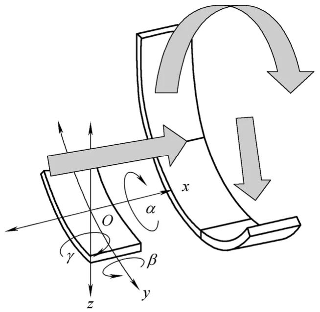
Fig. 3. Schematic diagram for segment manipulation
2.2 New segment erector design based on GF sets
2.2.1 Motion group-decoupling design approach
The motion group-decoupling design approach was firstly proposed by GUO, el at[13]. This approach is inspired from the GFSet Theory which will be introduced in the following section. The motion group-decoupling design works at the beginning of type synthesis. It could offer many schemes of motion combinations according to the scales and the sequence of motion. When two or more motions are generated together, a parallel mechanism(denoted as PM for short) is needed to be designed. When two motions are generated independently, the two actuators are serial connected. This process could be expressed in the formula below:
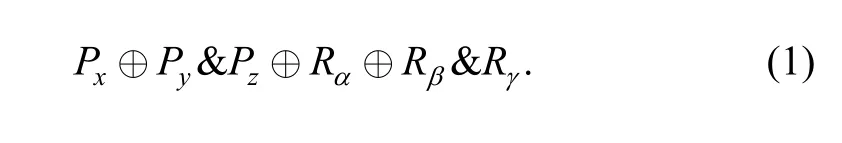
The symbol “⊕” means a series connection between the two kinematic pairs, and “&” means a parallel mechanism could execute such kind of motion. Finally a hybrid structure 6-DOF machine, with a 2-DOF translational PM and a 2-DOF rotational PM, is represented in Eq. (1).Obviously, “&” possess higher operation priority because it represents indivisible PMs. And also there are existing sequences between motions. The orders of some motions are exchangeable while some are not, the principle of motion sequence is discussed in the next section of the GFSet Theory. At last, the scales of motions play the key role in the evaluation and selection of schemes.
Most existing segment erectors share the similar series structure. According to the motion group-decoupling approach, the general structure of the existing 6-DOF segment erectors could be represented as the formula below:
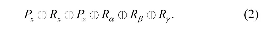
There is a general problem for the series mechanism that the more the actuators series connect together, the larger accumulative errors and the smaller rigidity the serial mechanism has[14]. There are two primary methods to improve those two problems. On way is to reduce the stress of each cylinder by increasing cylinders that are parallel to the working section radius. Or it is also practical to decent errors and increase rigidity by decreasing the number of serial mechanism.
According to the decomposition of motions in the previous section, a new 6-DOF segment erector which has a 4-DOF parallel mechanism is proposed to reduce the series kinematic pairs in the erector. With the consideration of the large scale movement requirement for segment erector, the original translation mechanism and gyration mechanism are preserved. Then the structure of the new 6-DOF segment could be represented as the following formula:
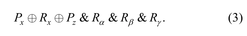
The new 4-DOF parallel mechanism would achieve the three micro motion as well as one macro motion which could pick or put segments along the working section radius, with the structure of Pz&Rα&Rβ&Rγ. The complex motions of the new segment erector require higher ability of design approach. A new approach for mechanism synthesis, titled the GFSet theory is applied and many schemes have been contrived by this new theory.
2.2.2 Introduction of GF Set
The GFSet is abbreviation of Generalized Function Set.GFSet is invented with the properties of dimensionless,non-algebra and irrelative with coordinate, in order to represent the outputting kinematical characteristics of robot[15]. All indexes of general kinematical characteristics of robot are 6 dimensions, and those 6 dimensions can be divided into 2 groups, 3 dimensions come from translations while the other 3 dimensions come from rotations, thus GFsets is defined by 6 elements:
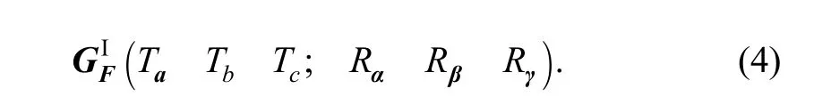
Among them, Ti(i=a, b, c) represents three dimensions translation characteristics of robot outputting, while Ri(i=α, β, γ) represents three dimensions rotation characteristics. According to the influence which happens when translation characteristics are combined with rotation characteristics with consideration of different orders of connecting, we need to divide GFSet into two categories,andThe details are listed in Ref. [15].
The features of robotic ends which can be described by the first category ofare that the rotation axes of rotation center of end effectors can move within the area where the translations can reach. On the contrary, rotation axes or rotation center of end effectors which are described by the second category ofcannot move arbitrarily even within the area where the translations are permitted.
The intersection operation of GFSet is the basis of parallel mechanism topology synthesis. And the translation combing theory and rotation combing theory are the basic rules of intersection operation for GFSet.
2.2.3 4-DOF parallel mechanism design based on GF Set.
The 4-DOF parallel mechanism possess four motions,including the motion of picking or putting segments along the working section radius, the motions of three dimensions orientation adjustment. Thus the characteristics of end effector of 4-DOF parallel mechanism could be represented asSuppose the 4-DOF parallel mechanism is composed by four kinematic chains, then each kinematic chain could be found by intersection operation of GFSet. Then finally 4 kinds of chains’combination could be contrived to achieve the ends’characteristics requests ofThey are listed in Table 1.
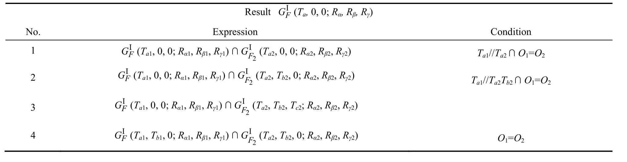
Table 1. Possible combination for 4-DOF parallel mechanism
Each expression contains a group of different kinematic chains’ combinations, which means that those different kinematic chains are identical in the GFSet. There are 4 typical schemes shown in Fig. 4. Among them, Fig. 4(a)has a 4-PRRR parallel mobile platform derived from expression No. 1. There is no scheme derived from expression No. 2 because the only difference between expression No. 1 and No. 2 is an additional prismatic joint on any kinematic chains. While Fig. 4(b) has a 1-PS&3-SPS platform derived from expression No. 3. And the mobile platform in Fig. 4(c) is composed by 2T3R-2T3R-2T3R- 2T3R chains derived from expression No. 4. Finally the scheme of Fig. 4(d) replace one RPUR kinematic chain with a RSS chain, but the combination also comes from expression No. 4.
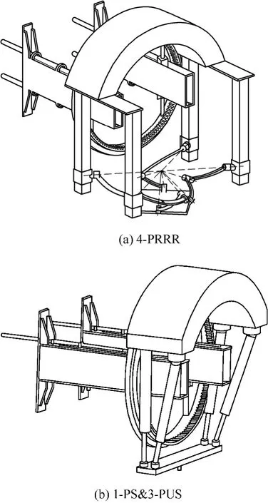
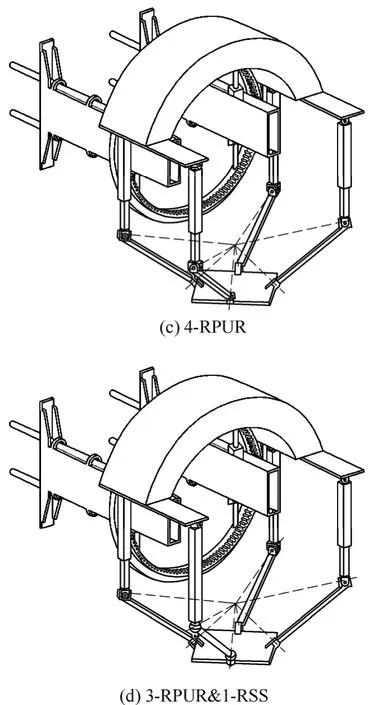
Fig. 4. 4-DOF Parallel Mechanism with characteristics of
2.2.4 Schemes evaluation & selection
The scheme in Fig. 4(b), which has 1-PS&3-PUS parallel mobile platform, is much simpler and more practical in building parallel mechanism for new segment erector from the application point of view. This scheme has three tremendous advantages. The first advantage is that 1-PS&3-PUS parallel mechanism is a reducible mechanism which is less coupled, easier to control and design the sizes[16]. The second advantage is that this scheme avoids the possibility of configuration singularity. Scheme B does not require any rotation axis from different legs interject at one point. The last but not the least advantage is that it also reduces the requirement of high accuracy in assemblage.The final scheme is 1-PS&3-UPS mechanism. And a series kinematical analysis, numerical simulation and prototype experiment would be performed to discover the properties of the 1-PS&3-UPS mechanism of the new segment erector.
At last, the 6-DOF segment erector is in the configuration ofThe 2-DOF serial mechanism makes the end effector moving along the tunnel marching axis and rotating around the axis, while the end effector execute 4-DOF motions to locate the segments on the right position and orientation in the working section.
3 Reducibility and Accuracy Analyses Based on Inverse Kinematics
The inverse kinematic models are built to analyze the kinematic performances of the new segment erector in this section. The reducibility and dexterity analysis are performed, while the parameters of reducibility and dexterity of 1-PS&3-UPS mechanism are directly obtained from Jacobian matrix based on inverse kinematics. The inverse kinematics is also the foundations of the control of prototype which is built for experimental study.
3.1 Inverse kinematics of parallel platform
There are two coordinate systems established to describe kinematical characteristics of the mobile platform. Points A1and B1are the origins of each coordinate frame, shown in Fig. 5.
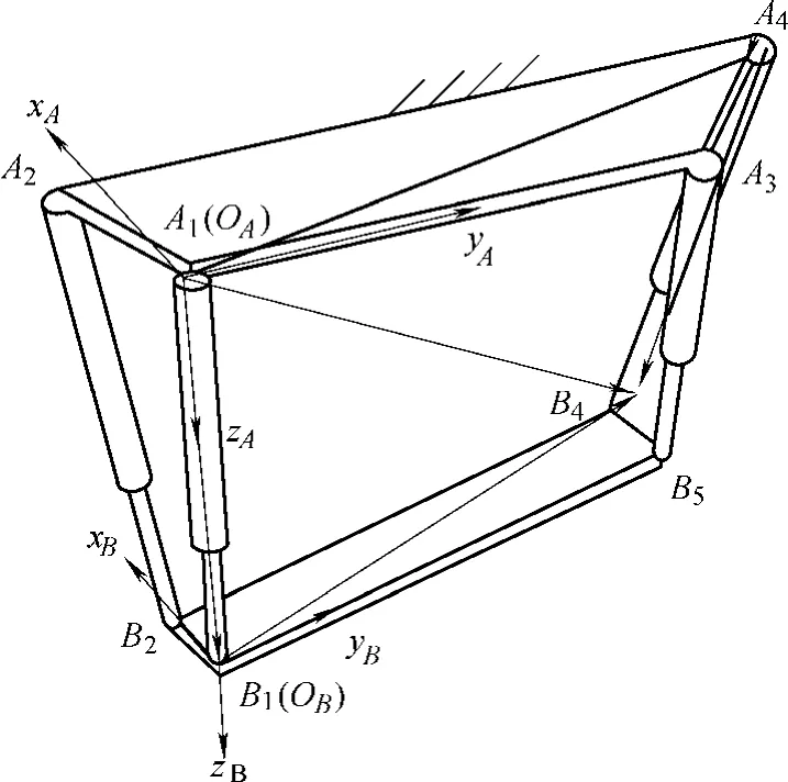
Fig. 5. Schematic diagram of 1-PS&3-SPS parallel mechanism
The z-axis of frame A is defined perpendicular to the stationary platform and towards the ground, y-axis is along line A1A3and point to A3, x-axis is derived by right-hand rule. Similarly, B1is the origin in the coordinate frame OB-xByBzBof moving platform, zB-axis is defined perpendicular to the moving platform and also point downward, yB-axis is defined along line B1B3and point to B3, xB-axis is derived by right-hand rule too.
3.1.1 Inverse solution of position
Given the position and orientation value of moving platform, RPY angle α, β, γ and z direction displacement dz,it is easy to get inverse-solution of the displacement of each cylinder li.
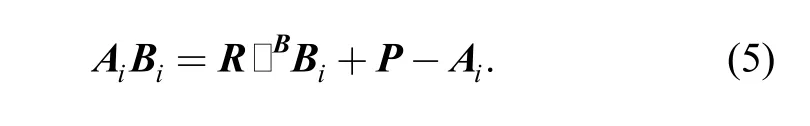
The displacement of each cylinder is solved by close loop vector method[17]. The vector AiBiequals the vertor OBBiplus vector P, which is the vector from the origin of the stationary frame to the origin of the moving frame.Then subtract vector OAAi, the vector operation is shown in Fig. 7. The numerical value of OBBiin stationary frame equals RbBi, while it is the same for vector OAAi. The vector operation formula is expressed below:
The character niis defined as the direction vector of AiBi,the length of cylinder and piston as Liand original length as L0i, then
Then Eq. (5) could be rewritten as follows:
The displacement of piston liis clearly:
In this case, displacement of leg No.1 is denoted as follows:
So, the displacement of leg No.1 is
For leg Nos. 2 to 4 (i =2, 3, 4), the endpoint vectors of each leg are
Since rotation matrix does not multiply with zero vectors,the results are shown as follows:
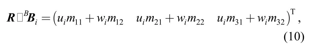
Denoting mijis element of rotation matrix. In this paper rotation matrix is derive by RPY angle, then mijis shown below[18]:
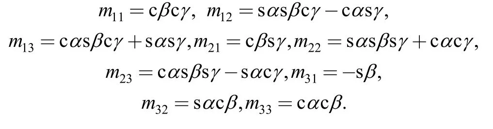
Then the vector of each leg is represented below:
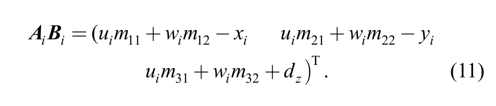
So the expression of the displacement of each leg liis
3.1.2 Inverse solution of velocity
After solving the displacement of each kinematic chain,it is natural to further obtain the general velocities of each of leg. Then Jacobian matrix, which is the most important formula in robotic manipulation and is also the foundations of many evaluations of mechanical properties, could be calculated[19].
Known translation velocity and the angular velocity of the moving platform is
A uniform vector formula which describes the relationship between the velocities of each leg and the velocity of the moving platform could be derived by differentiating Eq.(7), shown below[19]:
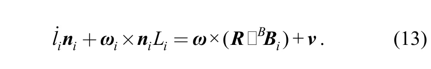
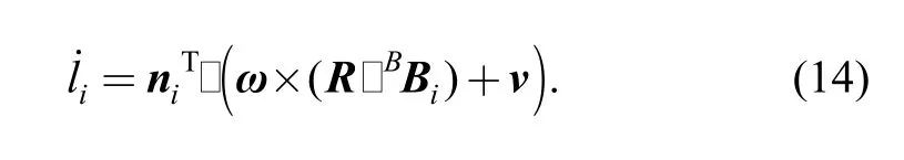
After multiplying niTby both sides of Eq.(12), the general displacement formula of each leg liis
And then the translation velocity of cylinder 1 is gotten by substituting n1=[0 0 1]T,the direction vector of leg No.1, as follows:
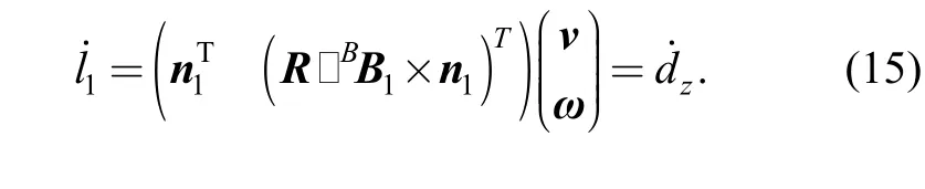
Because of leg No. 1 fixed on the stationary platform, the angular velocity is zero, ω1=(0 0 0)T.
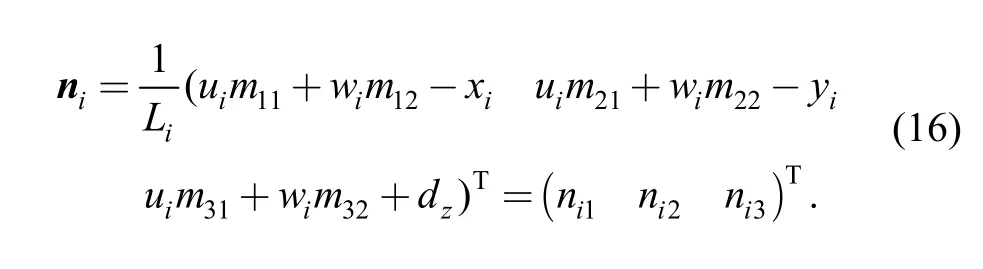
For leg No. 2 to No. 4, the direction vector nineeds to be calculated from Eq. (7) at first:
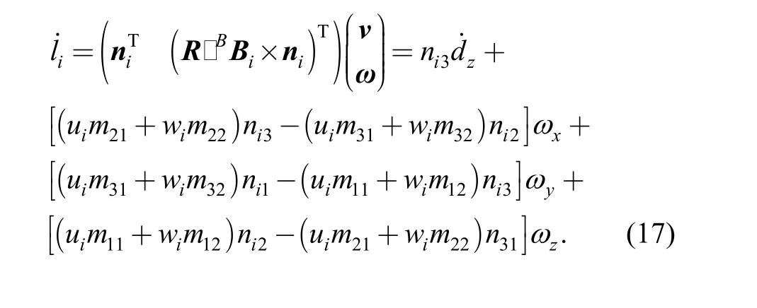
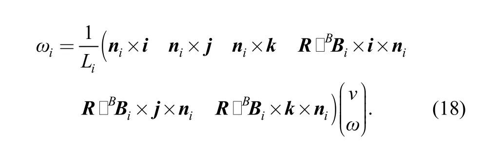
Then the expansion formula of the translation velocity of each leg is represented:
And the angular velocity is derived from Eq. (12):
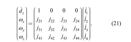
Combining all the velocity equations together, the inverse kinematical function is
where
Denoting matrix G is the first-order inverse motion influence coefficient matrix (or inverse-Jacobian matrix) of 1-PS&3-SPS mechanism, the size is 4×6.
The Jacobian matrix is derived by calculating the generalized inverse matrix of G:
After eliminating zero rows and lines on both sides of Eq.(19), such as the row of dxand dyon the left side, the final result is in the form below:
3.2 Reducibility analysis of 1-PS&3-UPS mechanism
The reducible mechanical system is a new concept of parallel mechanism synthesis, and is presented by Dr.ZHANG Yong in 2006. The reducible parallel mechanical system can not only reduce the difficulty of control, but also reduces the difficulty of size design tremendously. It is especially excellent at some applications like sensors,micro-motion robots and so on[16].
A parallel mechanical system is reducible if and only if there exists a grouping method that the generalized Jacobian matrix of the n dimensional system could be linearly transformed as a k partition diagonal matrix. The 1-PS&3-UPS parallel mobile platform is obviously a k=2 reducible mechanical system from the Jacobian matrix below:
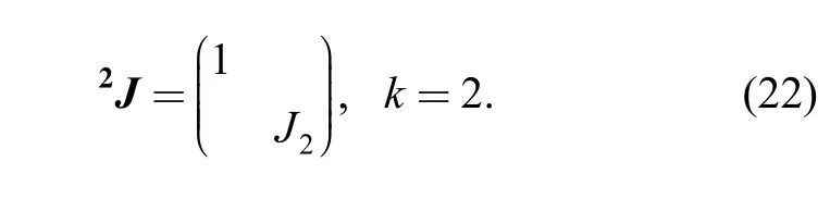
Eq. (22) shows that the translation along z-axis is only depend on the displacement of leg No. 1. Therefore, the motions of 1-PS&3-UPS could be divided into two groups.The translation motion is group one and the three rotation motions are in the other group. The length of leg No. 1 could be determined directly by the translation motion limits of the workspace without any calculation which can reduce the difficulty of size design tremendously.
3.3 Accuracy comparison between 1-PS&3-UPS and serial mechanism
Errors of parallel mechanisms are the consequence of many different origins. On one hand, the origin of error is static factors, like the clearance between kinematic pairs,errors from assembly; on the other hand the errors come from dynamic factors, such as actuators, vibrations and so on[20]. To simplify the comparison of error propagation between serial mechanisms and parallel ones, it is possible to assume all errors come from the actuators.
According to Eq. (11), the actual displacements of each leg could be calculated by substituting the actual position and orientation data. Assuming the percentage errors of each actuators of the two type mechanism are the same.Then, the error propagation of serial mechanism could be estimated by error transmit function as below[21]:
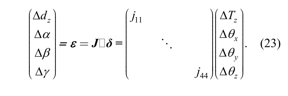
Where ε is the total estimated error of the end effector, J is Jacobian matrix, and δ is the actuators’ errors of serial mechanism with the same workspace as the parallel one. At last, the accuracy of serial mechanism and the 1-PS&3-UPS parallel platform could be comparable, and the result is shown in next section based on the data of calibration experiment of a prototype.
4 Case Study and Prototype
4.1 Virtual prototype of new segment erector
A CAD model of the new type Segment Erector was constructed with 1-PS&3-UPS parallel mobile platform with size parameters (unit millimeter) of the initial position as below:
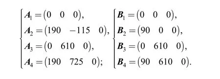
The initial distance between stationary platform A and moving platform B is 415 mm.
Then a virtual prototype system, shown in Fig. 6, is established by exporting the CAD model into simulation software, the ADAMS.
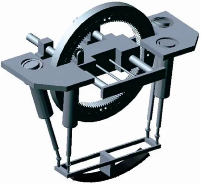
Fig. 6. Virtual prototype system in ADAMS
4.2 Numerical simulation
A series simulation of the 1-PS&3-UPS mechanism,including going up and down, to rotate around the x-axis,y-axis and z-axis separately, was performed under constant velocity to simulate the real segment erector working situation that most segment moves constantly.
Thus, the STEP function was applied to execute the four processes. Then the figures of the displacement of each leg are shown from Fig. 7 to Fig. 10 by letting the moving platform go back and forth by 100 mm, rotate around the x-axis, or y-axis, or z-axis about 5°in 4 s.
From those figures above, the new segment erector could achieve the motion requirement of design. Especially from the last three figures, the motion of rotation around the x-axis, y-axis and z-axis are all irrelevant with the translation of direction of the z-axis. This simulation numerically proofed that the 1-PS&3-UPS mechanism is reducible. And, there are no singularities within the whole workspace.
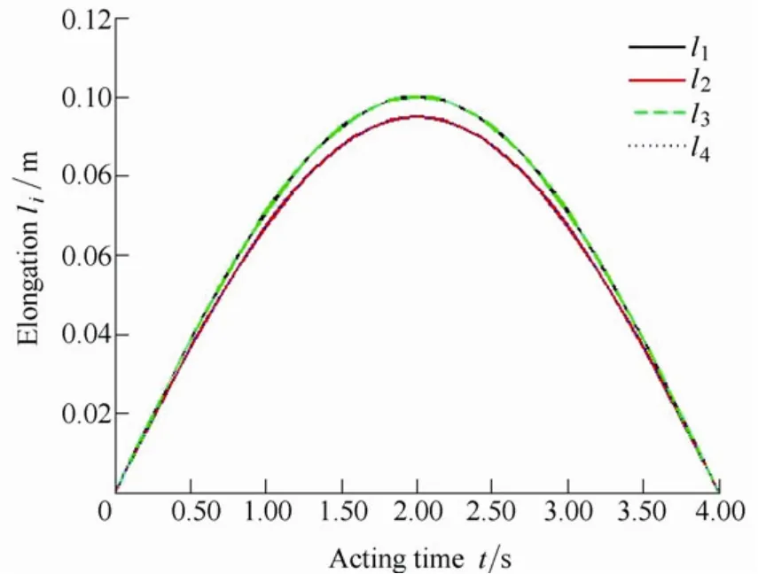
Fig. 7. Translation of 100 mm
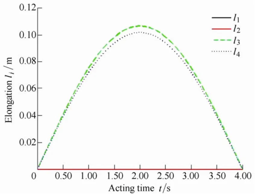
Fig. 8. Rotation around x-axis by 5
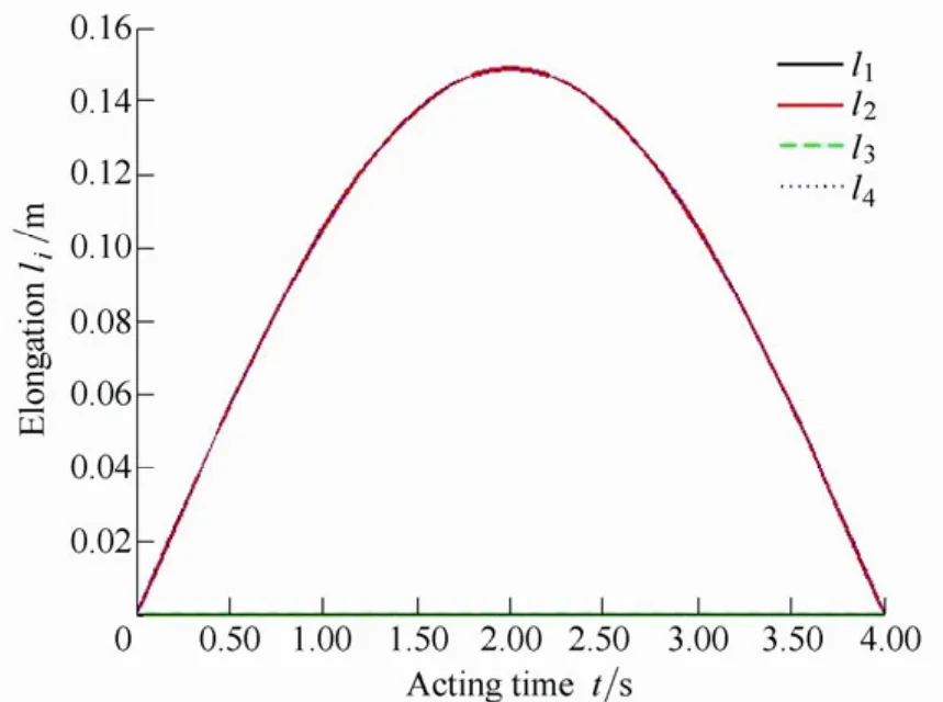
Fig. 9. Rotation around y-axis by 5
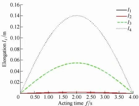
Fig. 10. Rotation around z-axis by 5
4.3 Dexterity analysis of new segment erector
In designing a manipulator, it is important to locate its workspace in the optimum location for the anticipated tasks[22]. When the manipulator is working near the singularities, there are huge distortions between the inputs and outputs. Since J, the Jacobian matrix, is a linear transform from each kinematic chain to end-effector, is also the transform of errors from chains to the ends as follows[14]:
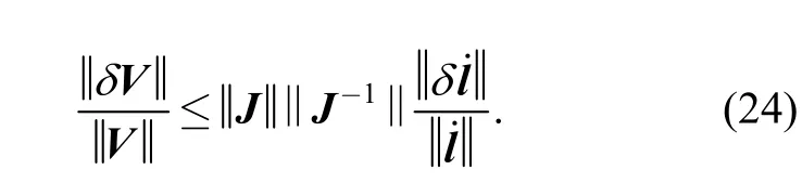
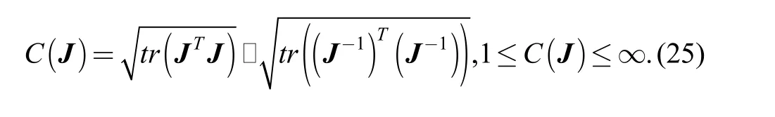
The condition number of the velocity transformation, J,is possible to predict distortion of different manipulator configurations. Therefore, the dexterity of parallel manipulator is defined as the condition number C(J). It will be checked below as an important performance index in evaluation of configuration synthesis.
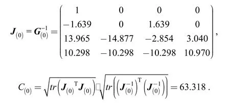
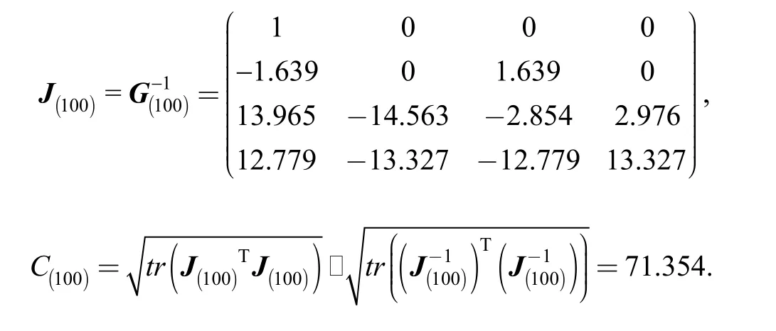
The numerical solutions of each state of the moving platform offer enough data to further check the dexterities of the 1-PS&3-UPS mechanism’s each configuration spaces.According to previous section 3.1, with all the parameters in standard units, the Jacobian matrix and condition number of initial position is
Then at position (0 0 100; 0 0 0) the dexterity is
Finally at position (0 0 100; 5 5 5) the dexterity is
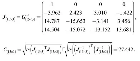
Due to the relatively large condition numbers, some distortions may occur when the moving platform moves to the edge of workspace of the 1-PS&3-UPS parallel mechanism, but within acceptable motion error.
4.4 Prototype & experiment
In order to further research the kinematical and dynamical performance of the new type segment erector, a prototype which is shown in Fig. 11, is built by the Institute of Design and Control Engineering for Heavy Equipment.
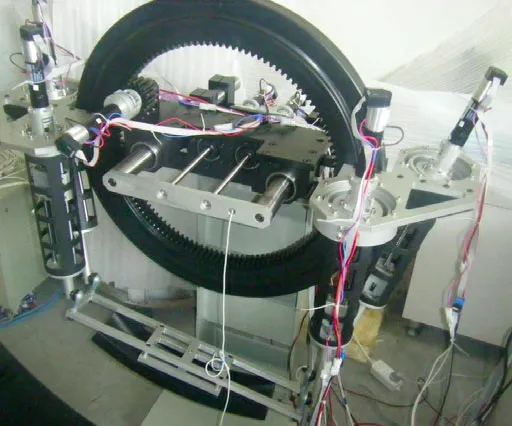
Fig. 11. Prototype of new type segment erector
In comparison with the CAD model, the size and structure of this prototype as basically the same, except a small difference. The hydraulic cylinders are replaced by screw and nuts due to the lighter loads in prototype.
The prototype can achieve the 6-DOF movement by seven servo electromotor, of which the nominal power is 60 W and provide a high accurate motion. The motor Nos. 1, 2,3 and 4 are placed above the stationary platform, driving screws on the endpoint of each leg. Motor Nos. 5 and 6 work together as the redundant actuators[23], driving the circular basement moving horizontally. The redundantly actuated interface module would enhance service life of the servo motors under the heaviest load in this prototype.Motor No. 7 is located on the center part of the circular basement, driving the rotation plate to gyrate around the tunnel axis.
A series of confirmatory experiments have being performed to examine the kinematical performances obtained from the kinematical analysis and simulation. The experiment measured the 6D coordinates of a point on the moving platform by the inputs from simulation. The processed measurement data, illustrated in Table 2, are obtained by high accuracy calibration device, the “Laser Tracker III” from API Corp. of the US. The theoretical position (50 mm, 5°, 0°, 0°)Twas executed on the prototype, and the actual movements were measured five times, and then calculated the averages and errors. The result was shown below.
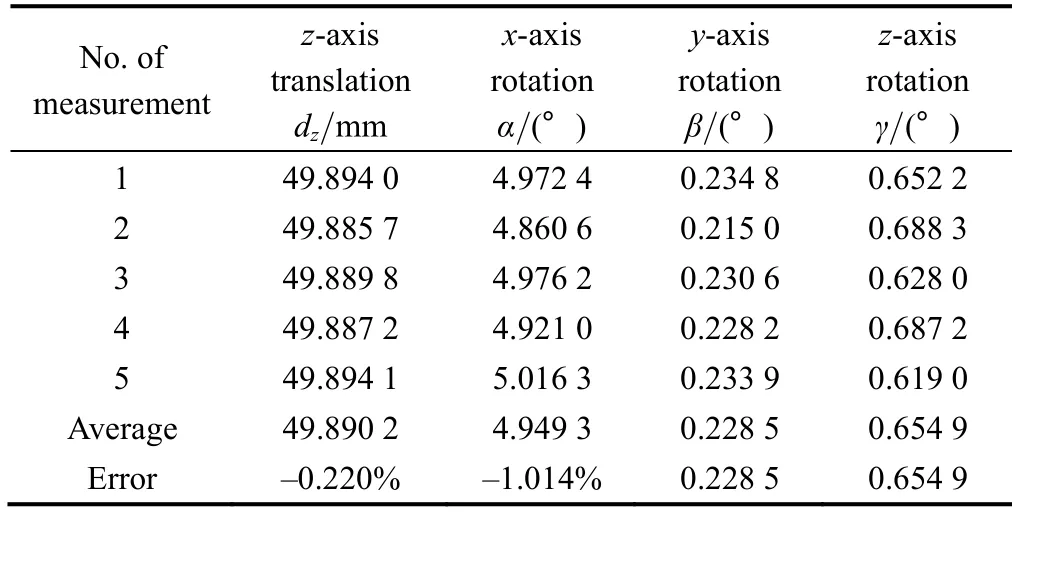
Table 2. Measurement Results
To compare the accuracy performance between the new segment error and a serial one, the first step is to calculate the actuator errors of each kinematic chain. Substituting average location value into Eq. (8), the estimated input error of serial mechanism is figure out, δ=(–0.109 8 mm,–0.011 0°, 0.228 5°, 0.654 9°)T. Then through Eq. (23), the estimated error of serial mechanism is ε=(–0.126 4 mm,–0.011 0°, 0.228 5°, 0.654 9°)T. The accuracy performance of z-axis translation improves 13.1%. There is no improvement in orientation accuracy because of no accumulative revolute joint in the last 4-DOF serial structures. If reconsider the total positioning error include the error of the frontal two macro motions, the accumulative error would show its influence.
5 Conclusions
(1) An innovative design method featuring motion group-decoupling is proposed, based on which a new type of segment erector is developed and investigated. And a 1-PS&3-UPS parallel mechanism is derived for the new segment erector by GFSet synthesis theory.
(2) This innovative design is a reducible mechanical system that can not only reduces the difficulty of size design, but also improves controllability of the segment erector.
(3) The maximum value of dexterity is acceptable and no singular points shown in the whole workspace through numerical simulation.
(4) The positioning accuracy of the 1-PS&3-UPS parallel platform improves 13.1 percent compare to a serial configuration through positioning experiments of a prototype of the new segment erector.
Acknowledgements
The author thanks Ms. GUO Jackie for her great help in writing skill and grammar of English.
[1] DENG Yingcong, GUO Weizhong, GAO Feng. Index of evaluation for performance of grouping of the thrust system of shield machines[J]. Chinese Journal of Mechanical Engineering, 2010,46(13): 122–127.
[2] KOYAMA Y. Present status and technology of shield tunneling method in Japan[J]. Tunnelling and Underground Space Technology,2003(18): 145–149.
[3] ZHANG Lixin, QIU Mingxuan. Technology of shield tunnelling in Beijing subway[J]. Railway Engineering, 2007(6): 35–37.
[4] CHHOUR K H. New 1-PS&3-SPS segment erector analysis and motion planning[D]. Shanghai: Shanghai Jiao Tong University, 2012.
[5] KOIZUMI A, KITAHARA Y, KIMURA S, et al. Investigation,design, construction of shield tunnelling[M]. Tokyo, Japan: The Geological Society of Japan Press, 1997.
[6] YANG Yonghua, GONG Guofang. Shield TBM and its applications of hydraulic technology[J]. Hydraulics Pneumatics & Seals, 2004(1):27–29.
[7] HAO Wanjun, ZHANG Yanwei, CUI Guohua. Research on the technical status of the segment-erection system for the full shield tunneling machine[J]. Mining & Processing Equipment, 2009,37(23): 1–5.
[8] CUI Guohua, WANG Guoqiang, HE Enguang, et al. Research status and development prospect of shield machine[J]. Mining &Processing Equipment, 2006, 34(6): 24–27.
[9] ZHANG Minqing, GE Daoyuan, HUANG Mingtao, et al. A segment erector with pressure sealing fuel tank: China, CN1448616[P/OL].2003-10-15[2012-10-15]. http://dbpub.cnki.net/grid2008/Dbpub/Detail.aspx? filename= CN1448616&dbname=SCPD0009&uid=WEEvREcw SlJHSldTTGJhYlRtcVdUam5pUnFkS0lPNnlTSmFqd1k4Q1h2M0J MaHhZbWk4Q1JCRE5zR2QxakFMVQ.
[10] SHI Yuanqi, WANG Helin, YANG Lei, et al. A 6-DOF segment erector: China, CN1837578[P/OL]. 2006-09-27[2012-10-15].http://dbpub.cnki.net/grid2008/Dbpub/Detail.aspx?filename=CN183 7578&dbname=SCPD0009&uid=WEEvREcwSlJHSldTTGJhYlRtc VdUam5pUnFkS0lPNnlTSmFqd1k4Q1h2M0JMaHhZbWk4Q1JCR E5zR2QxakFMVQ.
[11] HOU Xiangming. Application and development of shield machine and shield method[J]. Science & Technology Information, 2007(18):103–104.
[12] QIAN Xiaogang, GAO Feng, GUO Weizhong. Design and analysis of 6-DOF segment erector mechanism for shield machine[J].Machine Design and Research, 2008, 24(1): 17–20.
[13] GUO Wentao, GUO Weizhong, GAO Feng. The group-decoupling design of a segment erector based on GFset theory[C/CD] //Chinese Mechanical Engineering Society. Mechanical Transmission Division.International Conference on Mechanisms and Machine Science,China, Huangshan University, Huangshan, Anhui, July 16–19, 2012.
[14] HUANG Yeping. Mechanism design of the hinge equipment and segment erector for tunnel boring machine[D]. Shanghai: Shanghai Jiao Tong University, 2010.
[15] GAO Feng, YANG Jialun, GE Qiaode. The GFsets theory of parallel robots mechanism synthesis[M]. Beijing: Science Press, 2011.
[16] ZHANG Yong. Research on design theory and method of reducible parallel mechanisms[D]. Tianjin: Yanshan University, 2006.
[17] HUANG Zhen, ZHAO Yongsheng, ZHAO Tieshi. Advanced spatial mechanism[M]. Beijing: Higher Education Press, 2006.
[18] HUNT K H. Kinematic geometry of mechanisms[M]. Oxford:Clarendon Press, 1978.
[19] HUANG Zhen. Error analysis of position and orientation in robot manipulators[J]. Mechanism and Machine Theory, 1987, 22(6):577–581.
[20] CHEN Maosheng. Study on error in hybrid mechanism based on tripod universal wrist & biglide parallel mechanism[D]. Shenyang:Northeastern University, 2010.
[21] JIANG Chunying, FANG Lijin, XU Zhigang. A serial mechanism method for planar movement measurement and its comparison with parallel mechanism method[J]. Robot, 2007, 29(1): 67–77.
[22] SALISBURY J K, CRAIG J J. Articulated hands: force control and kinematic issues[J]. The International Journal of Robotics Research,1982, 1(1): 4–17
[23] LI Weimin, GAO Feng. A redundantly actuated interface module with force self-evening[J]. Chinese Journal of Mechanical Engineering, 2004, 15(2): 157–159.
杂志排行

Chinese Journal of Mechanical Engineering的其它文章
- Metamorphic Manipulating Mechanism Design for MCCB Using Index Reduced Iteration
- High Efficient Methods of Content-based 3D Model Retrieval
- Sewerage Force Adjustment Technology for Energy Conservation in Vacuum Sanitation Systems
- Simulation Research on the Effect of Cooled EGR, Supercharging and Compression Ratio on Downsized SI Engine Knock