Algorithm for Calculating Torque Base in Vehicle Traction Control System
2012-01-20LIHongzhiLILiangSONGJianWUKaihuiQIAOYanjuanLIUXingchunandXIAYongguang
LI Hongzhi ,LI Liang, *,SONG Jian ,WU Kaihui ,QIAO Yanjuan ,LIU Xingchun ,and XIA Yongguang
1 State Key Laboratory of Automotive Safety and Energy,Tsinghua University,Beijing 100084,China 2 Chang'an Automotive Engineering General Research Institute,Chongqing 400023,China
1 Introduction
In the traction control system(TCS),the slip rates of the drive wheels are regulated by driving torque and braking pressure.And the desired engine output torque requested by the TCS system,also called the target torque,can be calculated by PID controller[1].In the past decades,several controllers for the wheel slip control problem have been proposed,such as PI controller[2-5],nonlinear PID controller[1],self-tuning PID controller[6-7],sliding mode controller[8],fuzzy logic controller[9],self-tuning fuzzy logic controller[10],model predictive controller[11],and so on.The PID controller for automated machine is widely accepted by in the industry,as well as in the TCS system.Thus,effort on improving the PID control effect is of great worth.In the controller of PID class,a torque base is needed in the intervention procedure,because the intervention is not a long term process.When TCS entering into the control process,the PID control algorithm needs an initial value for integration;otherwise,the output of the target torque will be integrated from zero.Manyresearchers have made efforts on the control strategy of the TCS system,but not much attention have been paid to the torque base calculation.However,the calculation method of the torque base is important in torque control,because the driving performance of the vehicle can be bad if an improper torque base is calculated,especially in the short time after entering into intervention.A constant torque base is adopted by ISE,et al[2].VAN ZANTEN,et al[1],did not give a detail description of the nonlinear PID controller.LI,et al[6],PARK,et al[4],made the torque increase or decrease from the present value.IGATA,et al[3],calculated the torque base based on the road friction and engine speed.This paper focuses on the calculation method of the torque base of the PID torque controller.A comprehensive torque base is calculated based on two torque bases achieved by different methods;one is derived from states judgment method,and the other is derived from vehicle dynamics method.
This paper is organized as follows.In section 2,the vehicle and the tire models are briefly presented.The adopted vehicle model is a seven-degree-of-freedom(7DOF) model.The non-linear tire model adopted is the MF tire model.In section 3,the calculation method of the torque base is proposed.Then,in section 4,the simulation results and vehicle tests are shown and discussed.Finally,conclusions are presented in section 5.This paper supposes that the vehicle is front-drive in the analysis.
2 Vehicle Model and Tire Model
Since this study focuses on the control of the drive slip of the drive wheel,the nonlinear tire model,MF tire model,is used in the simulation.For both of the slip speeds of the drive wheels are used in the calculation of the confidence level of the tire-road friction coefficient,a four-wheel 7DOF vehicle model is adopted in the simulation in this paper.The engine model is an engine map,in which the output torque can be gotten by looking up table of throttle,engine speed,and torque.
2.1 Vehicle model
Fig.1 shows the model used in this research.The 7DOF vehicle model includes both the lateral and longitudinal dynamics.The degrees of freedom associated to this model are the longitudinal and lateral velocity (vx,vy),yaw angle(φ),and the wheels rotational speeds (ωfl,ωfr,ωrl,ωrr).The vehicle mass ismand the yaw moment of inertia isIv.The longitudinal and cornering forces are indicated at each wheel byFxij,Fyij,respectively,where the“ij”subscript denotes fl(front left),fr(front right),rl(rear left),and rr(rear right).No suspension is included in this model.The dimensionais the distance from the front axle to the CG(center of gravity),bis the distance from the rear axle to the CG,Lis the wheel base,andwis the track width.The radiuses of the wheels are indicated byRand the inertias of the wheels are indicated byIw.
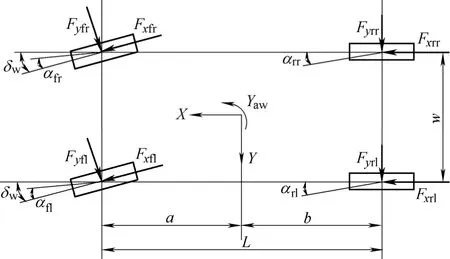
Fig.1.Vehicle model
The vehicle model may be as follows:
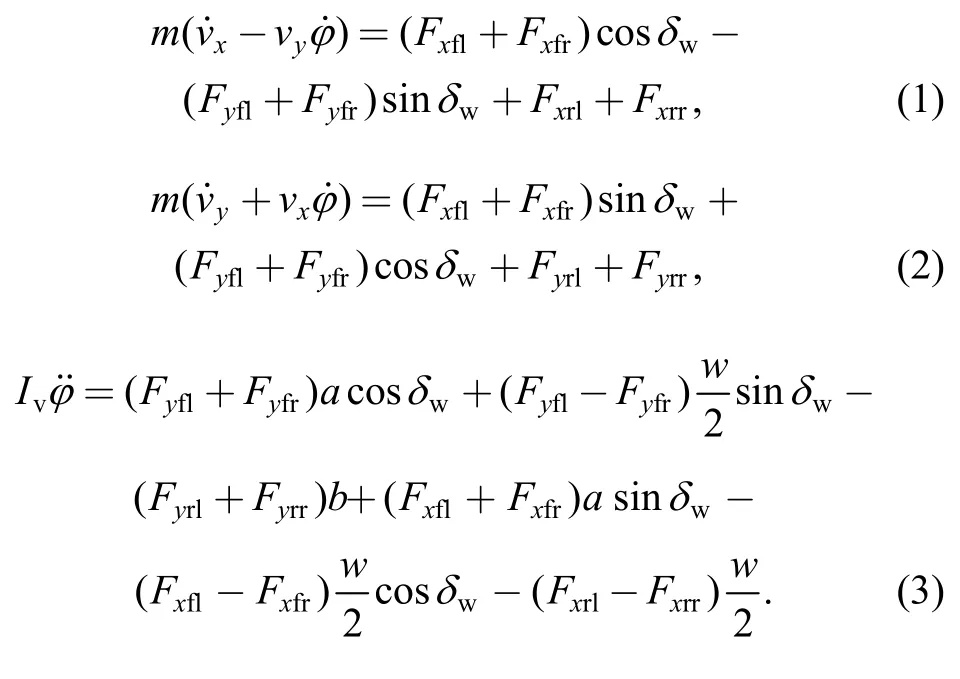
Wheels rotational motion is

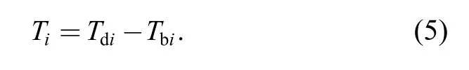
whereωi,Ti,Fxi,withi=fl,fr,rl,rr.Tiis the difference between the driving torque(Td) and the braking torque(Tb)applied toi-wheel:
For the focal point is driving slip control,lateral load transfer is neglected.Thus,the normal load equations for each wheel can be expressed as follows:
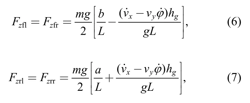
whereis the yaw rate of the vehicle.δwis the steer angle of the front wheels.Fzi,withi=fl,fr,rl,rr,is the vertical load.gis the acceleration of gravity,hgis the height of vehicle center of gravity.The values of the parameters of the vehicle model are shown in Table 1.
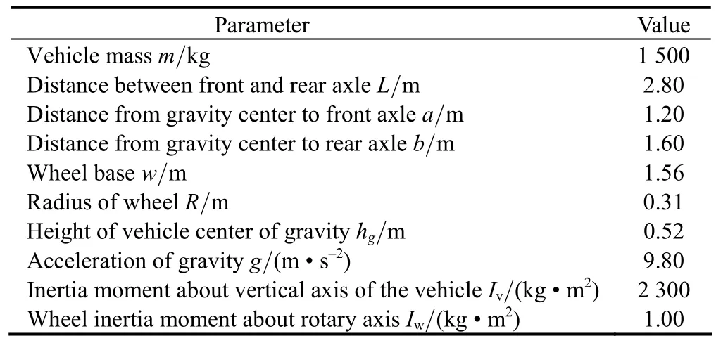
Table 1.Values of the parameters of the vehicle
2.2 Tire model
In the proposed method,the MF tire model[12]is adopted to simulate the lateral and longitudinal forces generated by tires.The MF tire model can be expressed as follows:
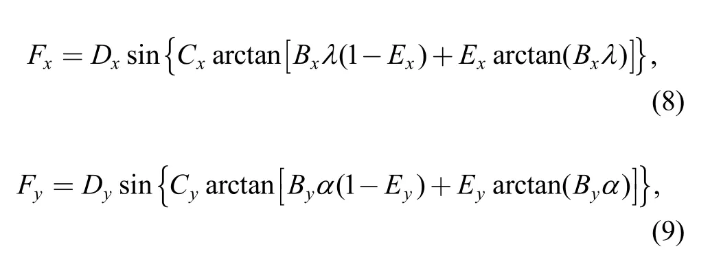
whereαis slip angle of tire,λis slip rate of the tire,Diis peak factor,Ciis shape factor,Biis stiffness factor,andEiis curvature factor,withi=x,y.These are tire parameters which are determinate for a certain tire.
3 Construction Logic of Torque Base
To give an overview of the whole controller,a brief description will be given in section 3.1.
3.1 Controller structure
In the TCS system,torque control and pressure control are included.The torque control is used for the regulation of all of the slip speeds of the drive wheels,while the pressure control is mainly used for the regulation of the difference of slip speeds between the drive wheels.For the focal point in this paper is the torque base calculation method of the PID torque controller,a simple PID torque controller and a PI pressure controller are adopted.As shown in Fig.2,the controller consists of a torque controller and a pressure controller.And in the torque controller,there are two modules;one is the torque base module,and the other is the PID torque controller module.
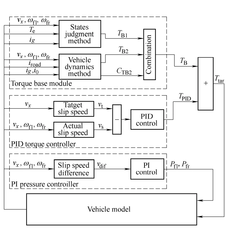
Fig.2.Diagram of the controller
As shown in Fig.2,for the focal point in this paper is the calculation method of the torque base,the PID torque controller and the PI Pressure controller are relatively simple.The PID torque controller and the PI pressure controller,which have a description by VAN ZANTEN,et al[1],will not be described in this paper.The target torque required by TCS,Ttar,can be expressed as
In most of the cases the torque base derived from the states judgment methodTB1is a proper value.However,if the slip speeds of the drive wheels are affected by the road roughness,or the engine output torque is disturbed,the torque baseTB1will be an improper value.Thus,another torque base derived from the vehicle dynamics methodTB2is introduced.The calculation method of torque baseTBwill de described in sections 3.2,3.3,and 3.4.
3.2 Torque base derived from states judgment method
Torque base can be obtained by states judgment method with engine output torque signal available vehicles.Actually the engine output torque signal is available with most of the vehicles equipped with TCS.The basic idea is that the torque base is the engine output torque when the drive wheel slip rate exceeding a threshold which is relatively small.Considering the translation delay between the engine output torque and the drive wheel slip,a time delay should be taken into account:
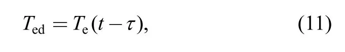
whereTeis the engine torque output,τis a constant time delay,determined by vehicle tests,andTedis the engine torque after time delay.
To reduce the noise in engine output torque signal,a one-order inertia delay should be implemented:
whereTedfis theTedafter filtering,andTis a time constant.
whereTB1is the torque base,vsis the total of the slip speeds of drive wheels,andvstis the threshold.
3.3 Torque base derived from vehicle dynamics
Torque base obtained by vehicle dynamics method is based on the vehicle dynamics.The torque base is the torque which can make the usage of road friction up to a high percent.The basic idea of torque base calculation by vehicle dynamics method is like this:Firstly,the longitudinal acceleration of the vehicleaxcan be calculated from the vehicle velocityvx;Then the peak value of road friction coefficientμpeand its confidence levelCμpecan be estimated byaxand drive wheel slipλfl,λfr;At last,the torque baseTB2and its confidence levelCTB2can be calculated based onμpe,Cμpe.
3.3.1 Torque base TB2and its confidence level CTB2
In order to get the peak value of road friction coefficientμpe,the normalized friction forceμuashould be calculated at first:
whereFxis the sum of longitudinal tire forces in drive wheels,Fzis the vertical load of drive wheels.Fxcan be expressed as
whereFfis the rolling resistance,Fiis the resistance due to gradients,Fwis the aerodynamic drag,andFjis the acceleration resistance.
The aerodynamic dragFwwill be neglected in this paper for it is very small.Then,Fxcan be expanded as
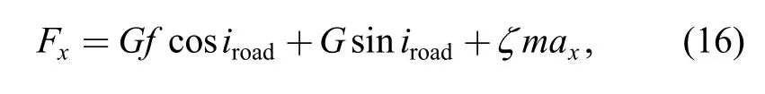
whereGis the gravity of the vehicle,fis the rolling resistance coefficient,iroadis the angle of gradient,which is supposed to be known,axis the longitudinal acceleration,andζis a mass factor.
The longitudinal acceleration of the vehicleaxcan be calculated from the vehicle velocityvx:
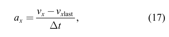
wheretΔ is the time interval betweenvxandvxlast,andvxlastis the vehicle velocity in last cycle.
The mass factorζcan be expressed as
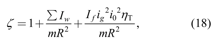
whereIfis the inertia of the rotating parts in power train,ηTis the transmission efficiency.
The vertical load in drive wheelsFzcan be expressed as
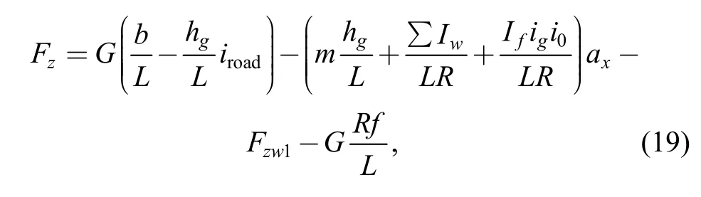
whereFzw1is the air lifting force at the front axle,which is small and will be neglected in this paper.
The peak value of road friction coefficientμpeand its confidence levelCμpecan be estimated by the normalized friction forceμuaand wheel slip.When the wheel slip is small,the normalized friction forceμuais much smaller than the peak value of road friction coefficientμpe.Thus,μpecannot be calculated with an accurate equation.Then based on human experiences,the fuzzy logic algorithm is employed to estimate the peak value of road friction coefficientμpe.The basic idea is like this:first the confidence levelCμpeofμpeis calculate based on the two slip rates of the drive wheels by fuzzy logic method,then the peak value of road friction coefficientμpeis calculated by Eq.(20):
The torque base by dynamics methodTB2and its confidence levelCTB2can be calculated withμpe.
The max tire forceFxpcan be expressed as
Generally,the engine output torqueTepcan be expressed as
The torque base by dynamics methodTB2is equal to the engine output torqueTep:
CTB2isdefined to beequaledto theconfidence level of peak valueof road frictioncoefficient,Cμpe:
3.3.2Cμpefrom fuzzy logic
The block diagram of the fuzzy logic algorithm is shown in Fig.3,the inputs are the wheel slip rates of the drive wheels,λfl,λfr,and the output is the confidence level of peak value of road friction coefficientCμpe.Because the range of the original signals is [0,1],there is no scaling module,which often appears in fuzzy logic algorithm.
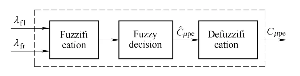
Fig.3.Block diagram of the fuzzy logic algorithm
(1) Fuzzification:It makes the measured inputs dimensionally compatible with the condition of the knowledge-based rules.In Table 2 the linguistic terms are shown.
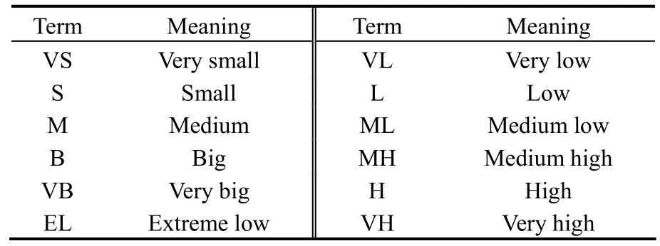
Table 2.Linguistic terms
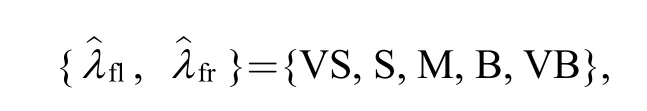
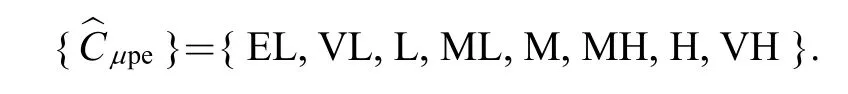
To provide enough rule coverage,five fuzzy sets are used for both inputs,and eight fuzzy sets are used for the output of the controller.flandfrhave a set of values between VS and VB,which is defined as follows:
andhas a set of values between NB and PB,which is defined as follows:
(2) Fuzzy decision process:It processes a table of rules from the knowledge base using fuzzy input from the previous step to produce the fuzzy output.Table 3 shows rules for the proposed fuzzy logic controller.These rules are introduced based on expert knowledge and the extensive simulations performed in this study.The rules comply with the following criteria:
1) If bothλflandλfrare close to a proper value,such as 7%,the normalized friction forceμuamay be very close to the peak value of road friction coefficientμpe.Thus,theCμpemay be very high.
2) If eitherλflorλfris close to a proper value,the other one is either too small or too big,the normalized friction forceμuamay be not so close to the peak value of road friction coefficientμpe.Thus,theCμpemay be not very high.
3) If neitherλflnorλfris close to a proper value,the normalized friction forceμuamay be not close to the peak value of road friction coefficientμpeat all.Thus,theCμpemay be low.
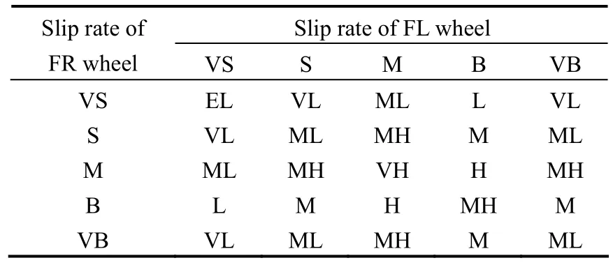
Table 3.Rule table of fuzzy logic
These criteria are the base of rules.Then,performing different simulations,we can tune them considering the effect of the drive wheel slip rate.The fuzzy controller uses the Mamdani Fuzzy Inference System (FIS)[13],which is characterized by the following fuzzy rule schema:
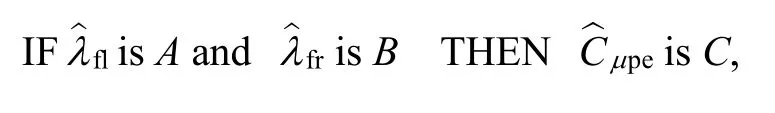
whereA,B,andCare fuzzy sets defined on the input and output domains respectively.
(3) Defuzzification:It scales and maps the fuzzy output from fuzzy decision process to produce an output value.The defuzzification method used in this paper is the centre of area.This method determines the centre of the area below the combined membership function.
Fig.4 and Fig.5 show the membership functions and ranges of values ofλfl,λfr,and,respectively.The universes of discourse of inputs are [0,1].
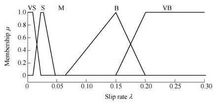
Fig.4.Slip rate membership functions

Fig.5.Cμpemembership functions
3.4 Combination of TB1and TB2
In section 3.2 and section 3.3,two torque bases have been calculated,and in this section,we will try to construct a more reliable torque baseTBby the two torque bases,TB1andTB2,and the confidence level ofTB2.The combination method can be expressed as Eq.(25):
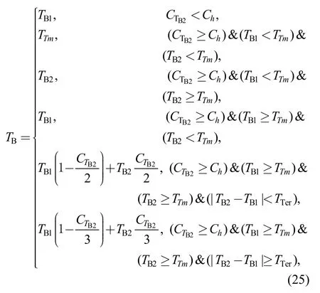
whereChis a threshold,TTmis the engine torque output limit,andTTeris a threshold.
Eq.(25) will be explained below.If the confidence level ofTB2is too small,thenTBwill only be determined byTB1.IfTB1andTB2are smaller than the lower limit of engine torque outputTTm,TBwill be determined by the lower limitTTm,as shown in area I in Fig.6.If eitherTB1orTB2is smaller than the lower limitTTm,TBwill be determined by the bigger one betweenTB1andTB2,as shown in area II and III in Fig.6.If the difference betweenTB1andTB2is small,a weighted average method with a relative big weight ofTB2will be used to calculateTB,as shown in area IV in Fig.6.And if the difference betweenTB1andTB2is large,a weighted average method with a relative small weight ofTB2will be used to calculateTB,as shown in area V and VI in Fig.6.
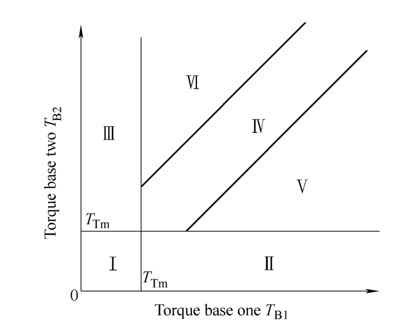
Fig.6.Combination logic of TB(CTB2≥Ch)
4 Results and Discussion
In this section,Hardware-in-the-Loop simulation results and vehicle tests of TCS with the proposed torque base calculation method are shown and discussed.The control algorithms of TCS are described in Ref.[14]and Ref.[15].Performance comparisons between the proposed torque base calculation method and the torque base derived from the states judgment method are presented.Why the torque base calculated by the states judgment method is chosen to be compared with the comprehensive calculation method?Because the vehicle dynamics method highly depends on the estimation of the road friction,the torque base calculated by the vehicle dynamics method cannot be got every time.The Hardware-in-the-loop simulation is carried out on the Hardware-in-the-loop simulation platform,as shown in Fig.7.
The experimental vehicle is equipped with a 5 gear automotive transmission,and other parameters are shown in Table 1.In the simulation and vehicle test,the time delayτis 0.1 s,the time constantTin the one-order inertial loop is 0.125.And the slip thresholdvstis 10 km/h.In all the tests in this section,the parameters of the PID torque controller and the PI pressure controller are the same.The steering angle is zero.In Fig.8,Pain the figures means the acceleration pedal,and theTtarequals 250 N · m when there is no torque intervention.
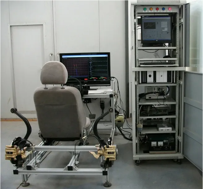
Fig.7.Hardware-in-the-loop simulation platform
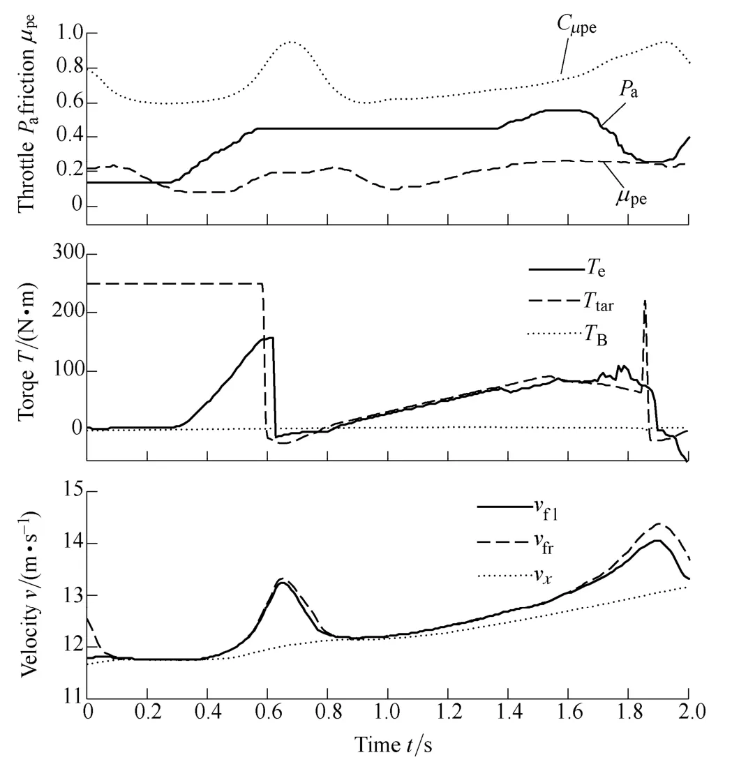
Fig.8.Simulation results with TB1as the torque base
4.1 HIL simulation result s
Simulation results shown in Fig.8 and Fig.9 have the same settings,including the acceleration pedal,gear ratio,road friction coefficient,and so on.In the simulation,the road friction efficient is set to 0.2,and there is no gear shifting.The only difference is the torque base,in Fig.8 the torque base is calculated by the states judgment method,and in Fig.9 the torque base is calculated by the comprehensive method.In Fig.8,the torque base is too small,consequently,the target torqueTtaris small,and so the engine output torqueTeis small.As a result the vehicle speedvxstops increasing from 0.8 s to 1 s,which means the tire-road friction is not fully used.At the end of the simulation,the vehicle speed is 13.15 m/s in Fig.8.By contraries,in Fig.9 the torque base is properly calculated,and thus the target torqueTtaris bigger than that in Fig.8.As a result,the acceleration of the vehicle in Fig.9 maintains large,and at the end of the simulation the vehicle speed is 13.55 m/s in Fig..
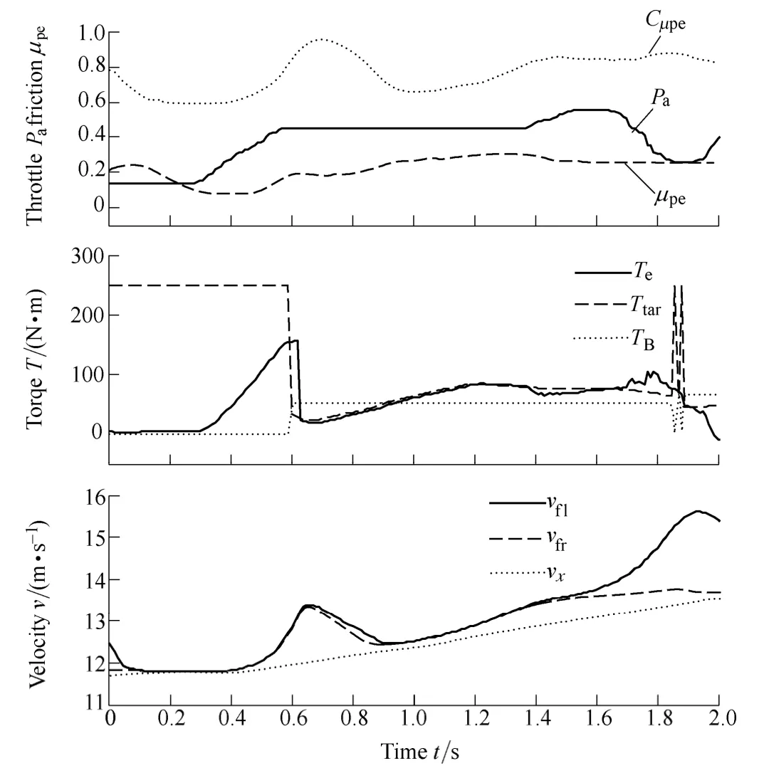
Fig.9.Simulation results with TBas the torque base
4.2 Vehicle tests
In the vehicle tests,the road friction coefficient is about 0.2,both in Fig.10 and Fig.11.
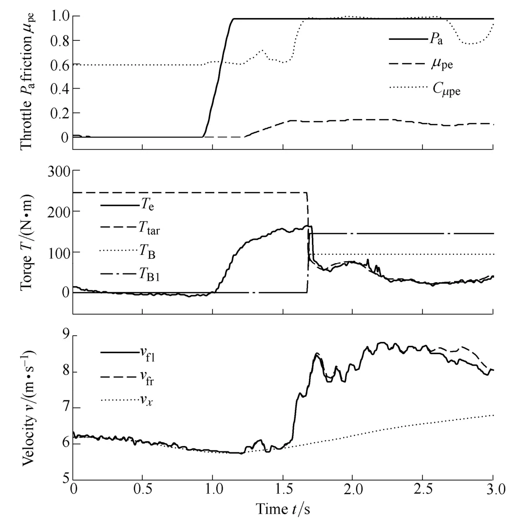
Fig.10.Vehicle test with TBas the torque base (TB1too large)
As shown in Fig.10,before 1.6 s,the engine output torque is big but the slip speeds of the drive wheels are small,and thus the torque base calculated by the states judgment methodTB1is relative large,while the torque base calculated by the comprehensive methodTBis much smaller.And the final torque base used in the vehicle test isTB.Thus,in Fig.10,ifTB1is used in the vehicle test,it is obvious that the target torque in the short time after entering into the intervention may be large.Consequently,the slip speeds of the drive wheels may be large,which would be a worse driving performance,compared with the performance shown in Fig.10.
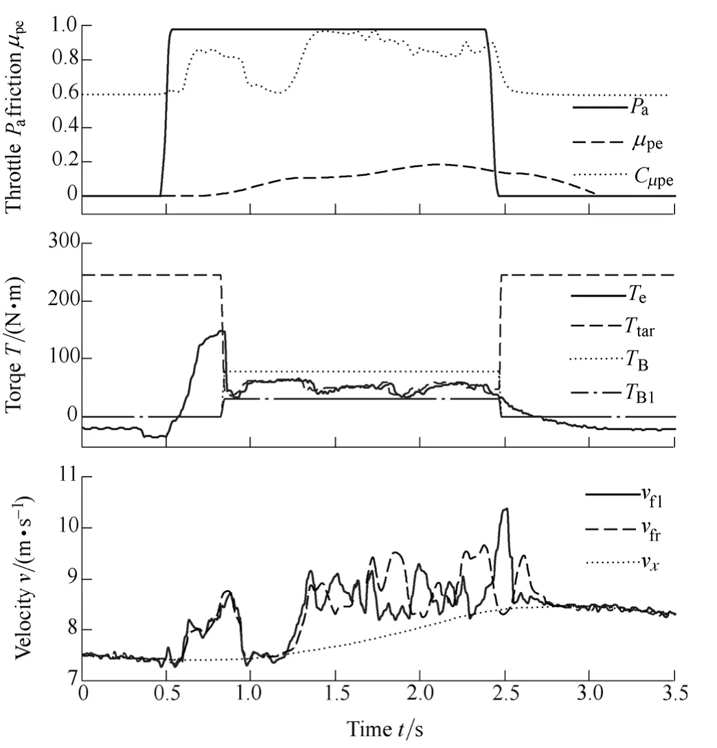
Fig.11.Vehicle test with TBas the torque base(TB1too small)
As shown in Fig.11,at about 0.7s,although the engine output torque is not big,the slip speeds increase and exceed the threshold,and thus torque baseTB1is very small.The reason of the improperTB1is probably the road roughness.While the torque baseTB,which is calculated by the comprehensive method,is a much proper value.And the final torque base used in the vehicle test isTB.In Fig.11,if the torque baseTB1is used in the vehicle test,it is obvious that the target torqueTtarin the short time after entering into the intervention may be small.Consequently,the acceleration ability of the vehicle may be small,which would result in a worse driving performance,compared with the performance shown in Fig.11.
5 Conclusions
(1) A comprehensive method of torque base calculation is proposed to get a more reliable value of the torque base,in order to improve the slip control performance.
(2) The proposed torque base calculation method is developed based on the two torque bases and a confidence level.One torque base is derived from states judgment method,and the other is derived from vehicle dynamics method.The confidence level is employed to indicate the reliability of the torque base calculated by the vehicle dynamics method.
(3) HIL simulations and vehicle tests are carried out to evaluate the effectiveness of the proposed method.And test results show that the vehicle with the torque base calculated by the proposed method has a better driving performance,compared with the vehicle with torque base calculated by the states judgment method.
[1]VAN ZANTEN A T.Control aspect of Bosch-VDC[C]//The 3rd International Symposium on Advanced Vehicle Control,Aachen,Germany,1996:573-607.
[2]ISE K,FUJITA K,INOUE Y,et al.The“Lexus”traction control(TRAC) system[G].SAE Paper,No.900212,1990.
[3]IGATA H,UCHIDA K,NAKATOMI T,et al.Development of new control methods to omprove response of throttle type traction control system[G].SAE Paper,No.920608,1992.
[4]PARK J H,KIM C Y.Wheel slip control in traction control system for vehicle stability[J].Vehicle System Dynamics,1999,31:263-278.
[5]LI Jing,LI Youde,ZHAO Jian,et al.Traction control algorithm for four wheel drive vehicle[J].Chinese Journal of Mechanical Engineering,2006,42(2):141-144.(in Chinese)
[6]LI Shoubo,LIAO Chenglin,CHEN Shanglou,et al.Traction control of hybrid electric vehicle[C]//The 5th IEEE Vehicle Power and Propulsion Conference,Dearborn,USA,2009:1 535-1 540.
[7]LI Liang,KANG Mingxin,SONG Jian,et al.Adaptive PID controller with variable parameters for vehicle traction control system[J].Chinese Journal of Mechanical Engineering,2011,47(12):92-98.(in Chinese)
[8]CHUN K,SUNWOO M.Wheel slip control with moving sliding surface for traction control system[J].International Journal of Automotive Technology,2004,5(2):123-133.
[9]KHATUN P,BINGHAM C M,SCHOFIELD N,et al.Application of fuzzy control algorithm for electric vehicle antilock braking/traction control systems[J].IEEE Trans.on Vehicular Technology,2003,52(5):1 356-1 364.
[10]LEE H,TOMIZUKA M.Adaptive vehicle traction force control for intelligent vehicle highway systems (IVHSs)[J].IEEE Trans.on Industrial Electronics,2003,50(1):37-47.
[11]BORRELLI F,BEMPORAD A,FODOR M,et al.An MPC/hybrid system approach to traction control[J].IEEE Trans.Control Systems Technology,2006,14(3):541-552.
[12]PACEJKA H B.Tyre and vehicle dynamics[M].Oxford:Butterworth Heinemann,2002.
[13]MAMDAMI E H,ASSILINA S.An experiment in linguistic synthesis with a fuzzy logic controller[J].International Journal of Man-Machine Studies,1975(7):1-13.
[14]ZHOU Yanxia.Research and development of the control algorithm of TCS system[D].Beijing:Tsinghua University,2007.(in Chinese)
[15]YANG Cai.Research on control algorithm of traction control system and on ABS/TCS/AYC integrated control strategy[D].Beijing:Tsinghua University,2009.(in Chinese)
Biographical notes
LI Hongzhi is a PhD candidate atTsinghua University,China.His current research includes vehicle nonlinear dynamic analysis and simulation.
LI Liang,PhD,is currently associate professor atState Key Laboratory of Automotive Safety and Energy,Tsinghua University,China.His current research interests include vehicle dynamics and control,vehicle CAE,vehicle system simulation and controller development.
SONG Jian is a professor atTsinghua University,China.He received his PhD degree fromTsinghua University,China,in 1990.He is a vice director ofStateKey Laboratory of Automotive Safety and Energy,Tsinghua University,China.His current research interests include vehicle dynamics and control,vehicle CAE.
杂志排行
Chinese Journal of Mechanical Engineering的其它文章
- Numerical Simulation of Pressure Fluctuations in a Large Francis Turbine Runner
- Optimal Design of Multiple Stress Constant Accelerated Life Test Plan on Non-rectangle Test Region
- Evaluating Local Elasticity of the Metal Nano-films Quantitatively Based on Referencing Approach of Atomic Force Acoustic Microscopy