LPCS Ni-Zn-Al2 O3Intermediate Layer Enhanced SPS NiCr-Cr3C2Coating with Higher Corrosion and Wear Resistances
2024-04-10BAIYangLIYanXINGLukuoLIXiangboWANGZhenhua
BAI Yang, LI Yan, XING Lukuo, LI Xiangbo, WANG Zhenhua
(1.State Key Laboratory of Marine Coatings, Marine Chemical Research Institute Co., Ltd., Qingdao 266071, China; 2.College of Mechanical and Electrical Engineering, University of China Petroleum (East China), Qingdao 266580, China; 3.Science and Technology on Marine Corrosion and Protection Laboratory, Luoyang Ship Materials Research Institute, Qingdao 266101, China)
Abstract: The double-layer NiCr-Cr3C2/Ni-Zn-Al2O3 coatings with sufficient corrosion and wear resistance were prepared on low carbon steel substrates.The intermediate layers Ni-Zn-Al2O3 were fabricated by using low-pressure cold spray (LPCS) method to improve the salt fog corrosion resistance properties of the supersonic plasma spray (SPS) NiCr-Cr3C2 coatings.The friction and wear performance for the double-layer and single-layer NiCr-Cr3C2 coatings were carried out by line-contact reciprocating sliding, respectively.Combined with the coating surface analysis techniques, the effect of the salt fog corrosion on the tribological properties of the double-layer coatings was studied.The results showed that the double-layer coatings exhibited better wear resistance than that of the single-layer coatings, due to the better corrosion resistance of the intermediate layer;the wear mass losses of the double-layer coatings was reduced by 70% than that of the single layer coatings and the wear mechanism of coatings after salt fog corrosion conditions is mainly corrosion wear.
Key words: low-pressure cold spray; NiCr-Cr3C2 coating; wear behavior; salt fog corrosion
1 Introduction
Non-skid coating, as a functional material with anti-slip effect, is deposited on the surfaces of ship decks to enhance the friction coefficient and is widely used in marine environment[1,2].Depending on the materials used, the non-skid coating can be divided into resin-based non-skid coating and metal-based non-skid coating[3].Although the resin based nonslip coating has been widely used, it has the following main shortcomings[3,4]: aging degradation; friction coefficient is not stable; wear-resistance performance is insufficient; poor adhesion; poor thermal shock resistance; toxic gases are released during construction and at high temperatures.
Compared with the resin based coating, the metalbased non-skid coating has excellent comprehensive properties such as high temperature resistance, light weight, strong bond strength, and easy pair[5].Therefore, the use of advanced spraying technology to prepare metal-based non-skid coating is one of the important directions in the development of non-skid coating.At present, the commonly used metal-based non-skid coatings are deposited by thermal spraying techniques,especially supersonic plasma spraying (SPS).SPS can not only fabricate high-quality metal and alloy coatings and metal ceramic composite coatings with high performance but also has good engineering application prospects because of its process stability, high efficiency and low cost[6].With the development and maturation of thermal spraying technology, the application of metal ceramic coatings will increase significantly[7].More attention has typically been paid to the friction and wear resistance of metal ceramic composite coatings and less to the effect of the coating corrosion process in the applied environments[8-11].However, in the extremely harsh service environments, even though the general single-layer metal ceramic coating can meet the requirements of anti-slip and wear resistance, it can not guarantee the corrosion resistance of that.In fact, the tribological properties of metal ceramic coatings in marine corrosive environments will be directly related to the long-term safe operation of equipments and the safety of people’s lives and belongings, which is of great significance.Therefore, metal ceramics composite coatings may be preferred for applications where corrosion and wear are of primary concern[12].
In previous work[13,14], it was found that the salt fog corrosion environment accelerated the deterioration of the tribological properties of the single layer NiCr-Cr3C2coatings; the addition of the LPCS Ni-Zn-Al2O3intermediate layers improved the corrosion resistance of SPS NiCr-Cr3C2coatings.The effect of salt fog corrosion on the tribological properties of doublestructured coatings are even less extensively explored.Thus, in this study, a systematic investigation was performed to understand the tribological behavior of the double-layer NiCr-Cr3C2/ Ni-Zn-Al2O3coatings,especially the influence of the salt fog corrosion.The wear mechanism of coatings before and after salt fog corrosion is discussed here in detail.
2 Experimental
2.1 Test materials
Plates (30×60×0.5 mm3) of Q235 carbon steel were used as the substrates.The under coat material was the mechanical mixed Ni-Zn-Al2O3powders.NiCr alloys contained 20 at% Cr agglomerated/sintered with 50 wt% Cr3C2powders.Two types of top-layer NiCr-Cr3C2powders with different fine and coarse grain size were used as the investigated top coat materials.The choice of the coarse-grain and fine-grain NiCr-Cr3C2powders was to study the influence of the grain size on the corrosion of double-layer coating.Substrates were degreased and grit-blasted to be cleaned and roughened before spraying.Double-layer coating systems comprising two types of SPS Ni80Cr20-50 wt% Cr3C2coatings with LPCS Ni-Zn-Al2O3underlying coating were deposited on Q235 carbon steel substrates.
It should be noted that the top coats of the doublelayer coatings with fine and coarse NiCr-Cr3C2grain size are referred to as FSC and CSC, respectively.The thickness of the Ni-Zn-Al2O3underlying coating of CSC and FSC is 170±15 μm and 300±15 μm,respectively.A single layer coating, as a blank control sample used the fine NiCr-Cr3C2powders.All NiCr-Cr3C2coatings were sprayed to a thickness of 300±15 μm.The optimized process parameters of LPCS and SPS used were provided elsewhere[13].
2.2 Characterisation techniques
The coating samples of 1 cm2were cut into small sections from the CSC and FSC for surface morphology and cross section microstructure.The cross-section of the coating was ground by 1 200# SiC sandpaper,and then polished with an alumina advanced polishing powder.The coating samples were degreased ultrasonically in acetone and dried in 100 ℃ oven.The morphology of the coating samples was observed using scanning electron microscopy (SEM) equipped with energy-dispersive spectroscopy (EDS).
The roughness tests were determined according to the national standard GB/T 1031-2009[15].The surface morphology of the samples were observed by using a HIROX KH-8700 three-dimensional microscope, and the roughness value was taken as the mean of 5 measurements.
The vickers microhardness tests were conducted on a HVS-1000 digital micro hardness tester according to the national standard GB/T 4340.1-1999[16].The polished cross-sections of the coating samples were carried out with a HVS-1000 digital micro hardness tester under a normal load of 300 g with dwell period of 15 s, and the mean of 10 measurements were determined as the microhardness value.
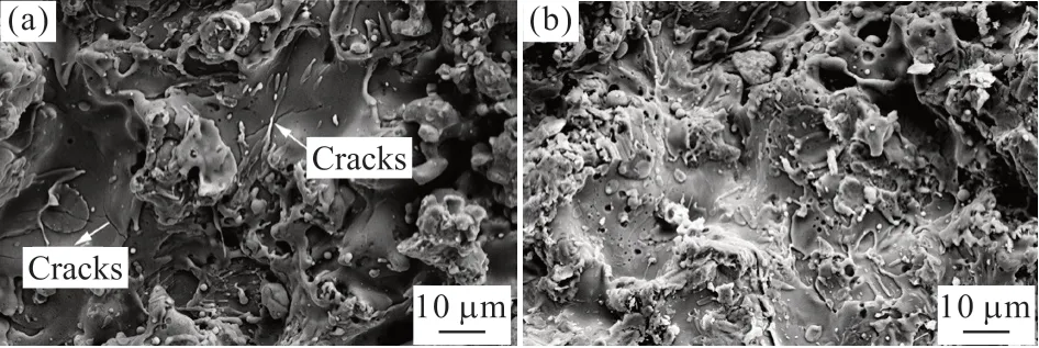
Fig.1 SEM micrographs corresponding to the surfaces of (a) CSC and (b) FSC
The tensile adhesive tests referenced the standard test GB/T 228-2002[17], and were carried out using a CMT 5305 electronic universal tensile machine.The tensile coating samples of 25 mm diameter were bond to cylindrical 304 L stainless steel with adhesive and cured agents, and the mean of 3 measurements was used as the adhesive strength value.
A neutral salt fog experiment was carried out with reference to the national standard GB/T 10125-2012 for simulating oceanic atmospheric corrosion[18].The neutral salt fog test were performed using a JK-FH90 salt fog chamber.The experimental solution is 3.5 wt%NaCl solution, the working temperature is (35±2) ℃,the pH value is adjusted between 6.5 to 7.2.It was noted that the total test time for the single layer and double layer coatings was 168 and 720 h, respectively.
The tribology tests of the NiCr-Cr3C2coating and Q235 steel pairs were measured by line-contact reciprocating sliding using a UMT-3 friction and wear tester.In this paper, the friction coefficient and wear performance test references the friction and wear testing program for organic non-skid coatings of the U.S.military standard MIL-PRF-24667C[19].The coefficient of friction was obtained from the movement of chloroprene rubber relative to the coating samples (150 mm×100 mm) at a load of 15 N, relative moving speed of 5 mm/s,and round trip of 70 mm.The wear losses were examined through the movement of a steel bar relative to the surface of the specimens (150 mm×100 mm) at a load of 45 N, relative moving speed of 2 mm/s, and round trip of 70 mm, based on the total wear from 650 repetitions.The mass loss of the specimen after wear from 0, 50, 200, 350, 500, and 650 repetitions was measured by a JA5003 electronic analytical balance (precision 0.1 mg).
3 Results and discussion
3.1 Microstructure properties
Fig.2 presents the SEM photographs corresponding to the surface and section morphologies of the sandwich structured coatings.As can be observed from Fig.2(a), the surface of NiCr-Cr3C2coating is uneven,the roughness is very large and there exists a small amount of small unmelted spherical particles.The cross section SEM image of the NiCr-Cr3C2coating with intermediate layer is shown in Fig.2(b).This coating has a dense and typical thermal spraying lamellar structure.It can be also found the close combination between Ni-Cr-Cr3C2coating and Ni-Zn-Al2O3coating.The orgnization characteristics of NiCr-Cr3C2coating is formed by the continuous NiCr binding phase and the irregular shape of carbide.Combinded with spectrum analysis of coating section selectionas shown in Fig.3, in the back sacttered images of the section of coating, the dark area is the uneven carbon particles, the gray area is hard carbide phase (polygonal), and white area is NiCr binder phase.
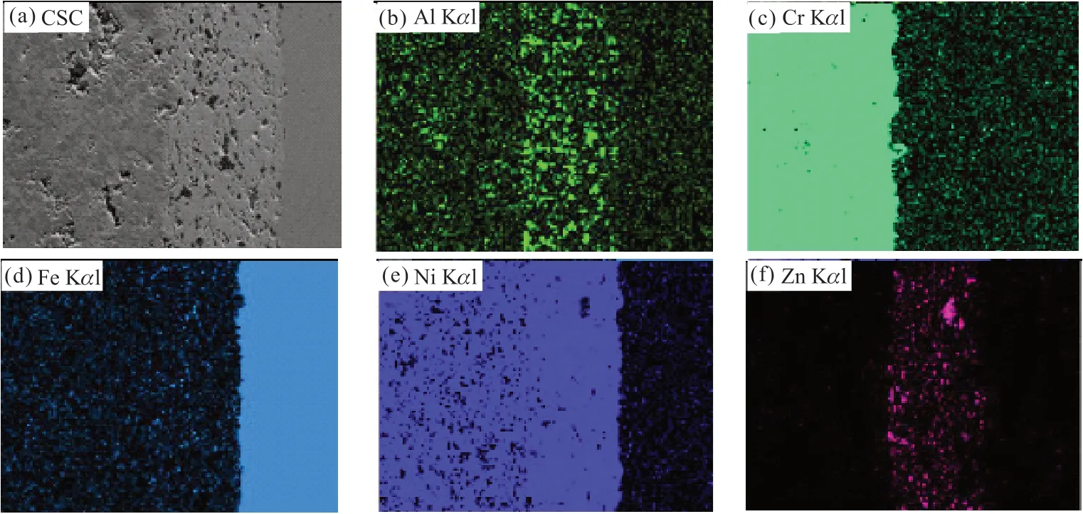
Fig.2 EDS mapping analysis of the cross-sectional morphology of CSC: (a) SEM image of CSC; (b) Al enriched region, shown in fluorescent green, EDS image; (c) Cr enriched region, shown in pale lake green, EDS image; (d) Fe enriched region, shown in pale peacock blue,EDS image; (e) Ni enriched region, shown in phthalo blue, EDS image; (f) Zn enriched region, shown in pale rose, EDS image
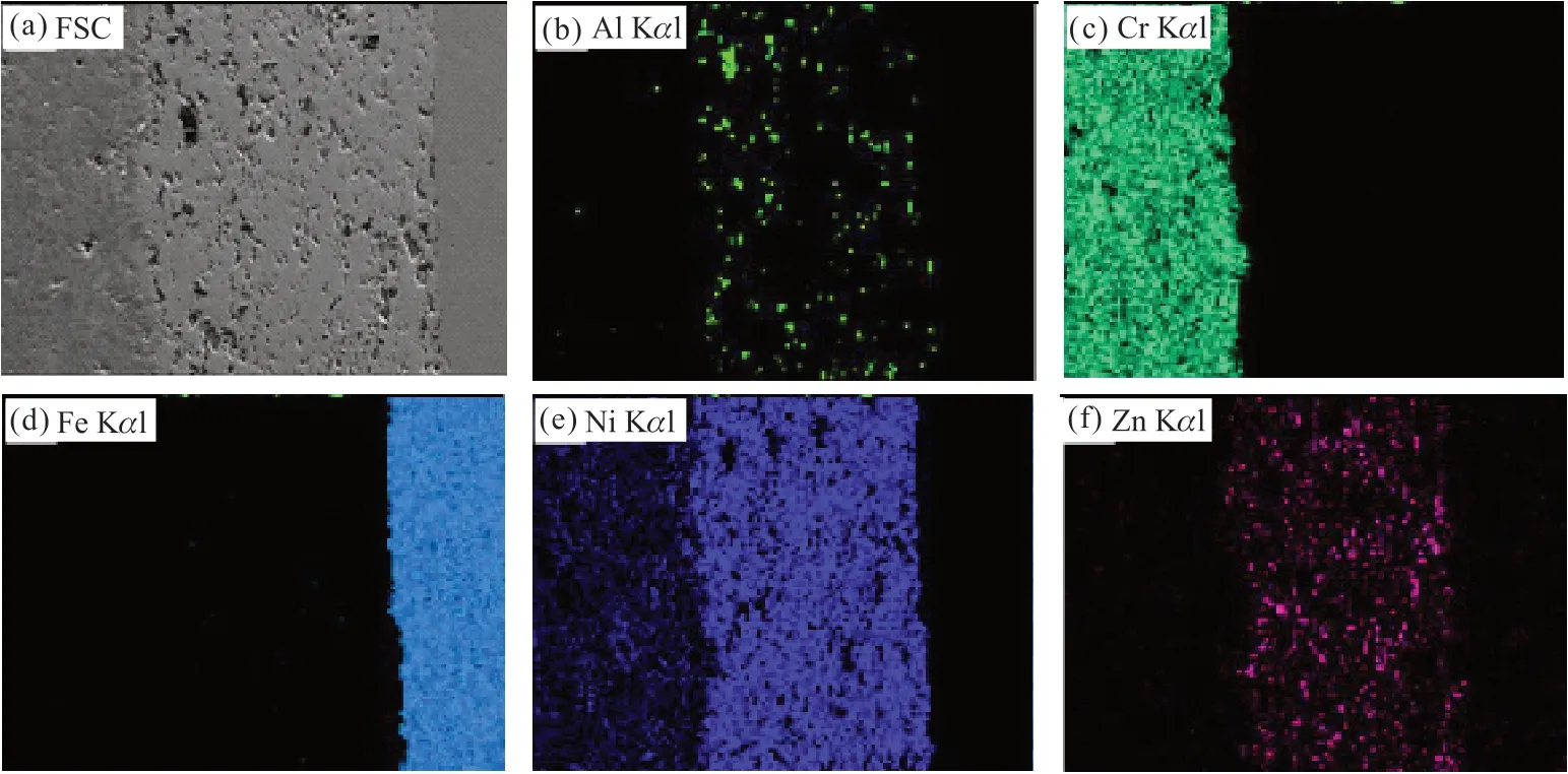
Fig.3 EDS mapping analysis of the polished cross-sectional morphology of FSC: (a) SEM image of CSC; (b) Al enriched region, shown in fluorescent green, EDS image; (c) Cr enriched region, shown in pale lake green, EDS image; (d) Fe enriched region, shown in pale peacock blue, EDS image; (e) Ni enriched region, shown in phthalo blue, EDS image; (f) Zn enriched region, shown in pale rose, EDS image
Fig.4 shows the X-ray diffraction pattern of the NiCr-Cr3C2surface layer.As can be seen from the XRD patterns, NiCr-Cr3C2coating is mainly composed of NiCr binding phase, carbide hard phase Cr3C2, Cr7C3,Cr23C6.And, the diffraction peak of coating specimen becomes wide near the diffraction angle 2θ=50o, which indicates that there are some amorphous coating.This is mainly because a large number of carbides was dissolved in the NiCr solid soulution during the deposition process[20].The presence of the carbide hard phases Cr3C2, Cr7C3, Cr23C6can effectively improve the wear resistance of the coating[10].
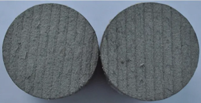
Fig.4 Photograph of the fracture section of the tensile fracture macroscopic topography of the FSC after pull-off test
3.2 Mechanical properties
Figs.5(a) and 5(b) show the macroscopic and the microstructural surface morphologies of the single layer coating after 168 h of salt fog corrosion.The presence of red rust is evident in Fig.5(a), and the steel substrate has almost certainly been corroded, due to the presence of porosities.In Fig.5(b), the white areas were clearly observed in the microstructure surface morphology and these were corrosion products.By comparing the EDS analysis results (as shown in Fig.6(a)) of the single layer coating before and after salt fog corrosion, it further confirmed the failure of the coating.Compared to the coating samples before salt fog corrosion, the elements Fe and O clearly increased after salt fog corrosion, suggesting that the corrosion resistance of the single layer coating is insufficient and need to be further improved.Figs.5(c) and 5(d)illustrate the surface morphologies of the CSC and FSC after 720 h of salt fog corrosion, respectively.It can be clearly seen that hardness, which to some extent reflects the wear and erosion resistance of the coating,is the reference value used to characterize a sprayed coating[21].On the basis of the measurement results, the average microhardness of the FSC reaches 675±54 HV,which is clearly lower than that of CSC (759±68 HV).The standard deviation reflects that both coatings have a non-uniform microhardness distribution, which might arise from the differences between the denser areas and the porous areas[22].

Fig.5 SEM images of coatings after salt fog corrosion: (a) the macroscopic and (b) the microstructural surface morphologies of the single layer coating after 168 h of salt fog corrosion; the microstructural surface morphology of (c) CSC and (d) FSC after 720 h of salt fog corrosion

Fig.6 Comparison of top coating surface elements of (a) the single layer coating and (b) the double-layer coatings before and after salt fog corrosion
Bonding strength is one of the most important factors in sprayed coatings because it is directly related to the coating’s durability[29].As observed in Table 1,the average bonding strength values of the CSC and the FSC is 14.0±3.0 MPa and 19.0±2.1 MPa, respectively.The specific tensile fracture macroscopic topography of the FSC after pull-off test is shown in Fig.4.After the pull-off test, there are some parallel lines on the surface of the FSC that correspond to the next passes of the spraying gun during the cold spraying process[23].In the FSC, the fracture was observed to occur at the interface of the top layer and the intermediate layer.

Table 1 Roughness, microhardness and bonding strength of spraying coatings
3.3 Salt fog corrosion
Figs.5(a) and 5(b) show the macroscopic and the microstructural surface morphologies of the single layer coating after 168 h of salt fog corrosion.The presence of red rust is evident in Fig.5(a), and the steel substrate has almost certainly been corroded, due to the presence of porosities.In Fig.5(b), the white areas were clearly observed and these were corrosion products.By comparing the EDS analysis results (as shown in Fig.6(a)) of the single layer coating before and after salt fog corrosion, it further confirmed the failure of the coating.Compared to the coating samples before salt fog corrosion, the elements Fe and O clearly increased after salt fog corrosion, suggesting that the corrosion resistance of the single layer coating is insufficient and need to be further improved.Fig.5(c) and Fig.5(d) illustrate the surface morphologies of the CSC and FSC after 720 h of salt fog corrosion, respectively.It can be clearly seen that the sloppy corrosion products formed on the top coating surface of the CSC and FSC, which suggests that the surface layer suffered corrosion and damage.To further confirm the composition of the corrosion products, the EDS technique were performed,and the EDS analysis results of both bond coatings were shown in Fig.6(b).It was found that the amount of elements Zn and O clearly increased, elements Ni and Cr drastically decreased, and Fe concentration remained nearly unchanged after 720 h of salt fog corrosion, indicating the electrolyte penetrated through the surface layer NiCr-Cr3C2coating and reached the surface-layer/inter-layer coating interface[25].It further proved that the intermediate layer plays a good corrosion resistance.As mentioned above, the doublelayer coatings enhance the corrosion resistance of the single layer coatings through the intermediate layer coating.
3.4 Tribological performance of coatings
The coefficient of the friction (COF) for the double-layer coatings varied with the wear repetitions,as shown in Fig.7(a).As the number of wear repetitions increases, the surface of coatings gradually becomes smooth; consequently, the roughness and friction coefficient are reduced.After the FSC was worn for 650 cycles, the COF of the FSC was lower than that of CSC, which can be ascribed to the surface roughness of FSC being approximately 40% lower than that of CSC.Fig.7(b) clearly shows that as the number of wear repetitions was increased, the wear mass losses of coatings progressively increased.After being worn for 650 repetitions, the CSC, the FSC, and the single layer coating had wear losses of approximately 0.008 1,0.006 6 and 0.007 8 g, respectively.The wear mass losses of the CSC is higher than that of the FSC, which mainly due to CSC containing more unmelted particles.The unmelted particles are easy to peel off under the test load (45 N), resulting in an increase in the weight losses of the CSC coating.

Fig.7 Coefficient of friction (a) and wear mass loss (b) of the double-layer coatings and single layer coating vs the number of wear repetition
Fig.8(a) shows the COF of the double-layer coatings and the single layer coatings after salt fog corrosion varied with the wear repetitions.For the single layer coating, the COF was lower than that of the double-layer coating and was only 0.75 before worn test.As the number of wear repetitions increases, the coefficient of friction rapidly increased to the maximum value of 0.82 and then gradually decreased and finally increased.For the double-layer coatings, as the number of wear repetitions, the coefficient of friction decreases first and then increases.The coefficient of friction of the double-layer coatings was lower than the dry coefficient of friction.Fig.8(b) shows that as the number of wear repetitions was increased,and the wear mass losses of coatings continuously increased.After being worn for 650 repetitions, the CSC, the FSC and the single-layer coating had wear losses of approximately 0.028 9, 0.034 3 and 0.103 g, respectively.The wear mass losses of the single layer coating are about 5 times more than that under dry friction and wear conditions, which demonstrates that the salt fog corrosion environment accelerates the deterioration of coating’s tribological properties and the corrosion resistance of the coating remains to be further improved.The wear mass losses of the double-layer coatings was reduced by 70% than that of the single layer coatings, indicating that the double-layer coatings can delay the deterioration of the tribological properties of the coatings.The authors argued that, the wear mass losses of the single layer coatings are higher than that under dry wear conditions, which is mainly due to the losses of the iron corrosion products.At the earlier EDS analysis, the corrosion resistance of the single layer coating has been corroded, which further confirming the presence of iron corrosion products.The wear mass losses of the double-layer coatings is also higher than that under dry wear conditions, which is mainly due to the removal or damage of the passive film comprising of Zn.

Fig.8 Coefficient of friction (a) and wear mass loss (b) of the double-layer coatings and the single layer coating after salt fog corrosion vs the number of wear repetition
3.5 Wear mechanism of coatings
Fig.9 shows the wear-track morphologies of the CSC and the FSC.On the worn surface of the CSC(Figs.9(a) and 9(b)), additional deep furrows and scratches are present on the coating surface, and the direction of the furrows is in the same direction as the speed, mainly because of the relative sliding that occurs between the abrasive grains and the coating surface,i e, three-body abrasive wear[25].Figs.9(c) and 9(d) show the wear tracks on the FSC; compared with the tracks on worn surface of the CSC, the observed wear tracks are comparatively shallow.Moreover, these wear tracks are a sign of abrasive wear.Combined with the wear mechanism of the single layer coatings, mentioned in the previous works[26], the wear mechanism for the double-layer coatings is the same as that of the single layer coating, which is both abrasive wear and adhesive wear[27].

Fig.9 SEM morphologies of the wear scars on the top coating surfaces: (a) 200× magnification and (b) 1 000× magnification of the CSC; (c)200× magnification and (d) 1 000× magnification of the FSC
The SEM morphologies of the worn surface for coatings after salt fog corrosion are shown in Fig.10.For the double-layer coatings, there are a large number of zinc corrosion products on the worn surface (Figs.10(b) and 10(d)), as detected by EDS.Fig.11 shows the wear process of the double-layer coatings after salt fog corrosion.The three different wear regimes in a wear process in sliding contact between double-layer coatings sliding against Q235 steel bar.Type I relates to the removal or damage of zinc passive films on coatings.At this stage, the zinc passive films has broken, and a larger particle size of the debris and corrosion products peeling block were produced, which led to the occurrence of three body abrasive wear and corrosion wear; the COF is at a high level and high wear.Type II relates to the formation of the adhesion layer on Q235 steel bar surface.The transferred material is comprised of zinc corrosion products.At this stage, the coefficient of friction have decreased, which is because the smoothed surface layer inhibits direct adhesion between the counterpart and the top-layer NiCr-Cr3C2coating.Type III relates to abrasion of the coating during subsequent sliding.As the number of wear repetitions increased, the adhesion layers are destroyed and caused third body abrasive wear, resulting in increased coefficient of friction and wear.However, the friction and wear in this stage are lower than that in the initial wear, which is mainly due to the friction-reducing and adhesionpreventing actions of the wear products from the toplayer coating[28].Therefore, the wear mechanism of the double-layer coatings after salt fog corrosion is also mainly corrosion wear.

Fig.10 SEM morphologies of the wear scars on the top coating surfaces after salt fog corrosion: (a) 200× magnification and (b) 1 000×magnification of the CSC; (c) 200× magnification and (d) 1 000× magnification of the FSC
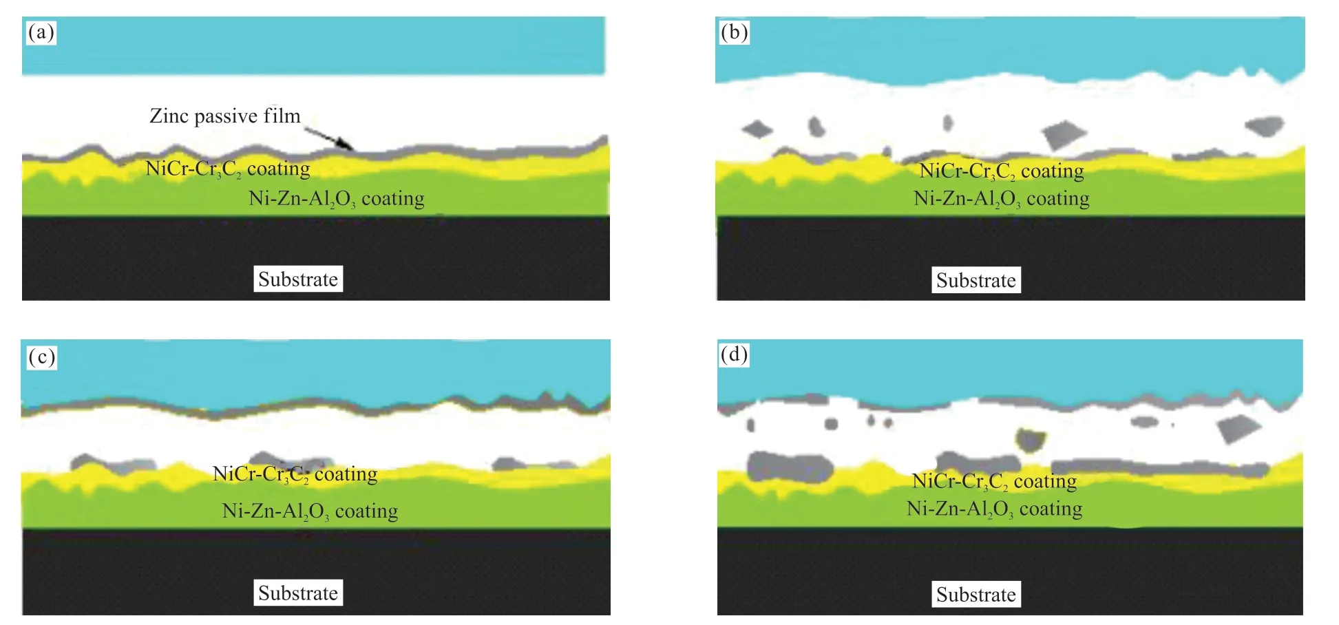
Fig.11 Major types of the wear process for the double-layer coatings after salt fog corrosion: (a) the initial surface before wear; (b) type I relates to the removal or damage of zinc passive films; (c) type II relates to the formation of the adhesion layer; and (d) type III relates to abrasion of the coating
4 Conclusions
The present study investigated the influence of the salt fog corrosion on the tribological properties of the double layer NiCr-Cr3C2/Ni-Zn-Al2O3coatings and the microstructure, mechanical, properties were also analyzed.The main conclusions drawn from the analysis are as following:
a) The top coating surfaces of both bond coatings exhibit relatively smooth surface and are composed of sufficiently flattened particles; the porosity of the surface layer of the CSC and FSC is 2.0% and 1.5%,respectively; the thickness of the intermediate layer of the FSC is about two times thicker than that of the CSC; the surface layer of the FSC has a denser structure than the surface layer of the CSC.
b) The roughness of FSC is lower than that of CSC, mainly due to the smoother surface of FSC; the standard deviation reflects that both coatings have a non-uniform microhardness distribution and the average microhardness of the FSC reaches 675±53.78 HV, which is clearly lower than that of CSC (759±68.23 HV); the average bonding strength values of the CSC and the FSC is 14±3.00 MPa and 19±2.08 MPa,respectively.
c) The results of salt fog corrosion showed that the single layer coating suffers severe corrosion attack and the steel substrate has almost certainly been corroded after 168 h of salt fog corrosion; the doublelayer coatings exhibit good corrosion resistance and large amount of zinc corrosion products produced on the coating surface after 720 h of salt fog corrosion.
d) Under dry friction and wear conditions, the wear mass losses of the CSC is higher than that of the FSC and the wear mechanism of the double-layer coatings is mainly abrasive wear and adhesive wear;the wear mass losses of the double-layer coatings was reduced by 70% than that of the single layer coatings and the wear mechanism of coatings after salt fog corrosion conditions is mainly corrosion wear.
Conflict of interest
All authors declare that there are no competing interests.
杂志排行
Journal of Wuhan University of Technology(Materials Science Edition)的其它文章
- Effect of VEGF/GREDVY Modified Surface on Vascular Cells Behavior
- Evolution of Biofilm and Its Effect on Microstructure of Mortar Surfaces in Simulated Seawater
- Synthesis of Organic-Inorganic Hybrid Aluminum Hypophosphite Microspheres Flame Retardant and Its Flame Retardant Research on Thermoplastic Polyurethane
- Surface Metallization of Glass Fiber (GF) /Polyetheretherketone (PEEK) Composite with Cu Coatings Deposited by Magnetron Sputtering and Electroplating
- Effect of Size Change on Mechanical Properties ofMonolayer Arsenene
- Effects of Sinusoidal Vibration of Crystallization Roller on Composite Microstructure of Ti/Al Laminated Composites by Twin-Roll Casting
