Preparation and Properties of Magnesium Oxysulfide Cement Based Foam Board Absorbing Material
2024-04-10LIUJunCUIBaodongPANGBo
LIU Jun, CUI Baodong, PANG Bo
(School of Materials Science and Engineering, Shenyang Ligong University, Shenyang 110159, China)
Abstract: In order to better solve the problem of electromagnetic pollution in the civil building cement, to improve the absorption capacity of magnesium oxysulfide cement based materials, and to better use sulfur oxide magnesium cement foamed sheet for improvement of electromagnetic industry, this paper uses the excellent microwave absorbing properties of ferrite and the modified sulfur oxide magnesium cement foam board, and discusses the microwave absorbing performance, aiming at improving the electromagnetic pollution in daily life.The effects of ferrite and silicon carbide doping on microwave absorption properties of modified magnesium oxysulfate cement were studied.At the same time, the wave absorbing properties of the corresponding samples were detected by bow method, and the causes of the corresponding phenomena were analyzed by scanning electron microscopy (SEM).The results show that the lowest reflectance of the material is -17.9 dB at 34.1 GHz and the average reflectance of the whole band is -15.9 dB under the target frequency band of 26.5-40 GHz.Under the action of external magnetic field, the absorbing particles are affected by magnetization force, magnetic dipole and resistance coupling, and play the absorbing effect in the cement base solidified completely in the electromagnetic field environment.The lowest reflectance is -17.3dB at 36.4GHz and the average reflectance is -14.3dB for the whole band.
Key words: magnesium oxysulfide cement; silicon carbide; ferrite; absorption properties
1 Introduction
Our country contains rich magnesite resources,which provides rich raw material for extensive application of magnesite cementitious material[1].But the electromagnetic shielding efficiency and absorption of magnesium cement itself are relatively low, which limits the development of magnesium cement itself.The cement material is modified by adding certain additives to achieve the shielding and absorption of electromagnetic radiation[2-4].Among them, carbon(graphite, carbon black and carbon fiber) and metal(metal powder, metal fiber and metal sheet) are the most common and widely used absorbing materials[5-7].As a special kind of cement, magnesium cement is commonly used in three kinds: magnesium oxysulfide cement, magnesium phosphate cement, and magnesium chloride cement[8].At present, magnesium chloride cement is the most commonly used cement, but it has some shortcomings such as moisture absorption and reverse halogen, poor water resistance and deformation[9].Therefore, magnesium oxysulfide cement products with low thermal expansion, small thermal conductivity and good volume stability that can fundamentally solve the problem of frosting and halogen return and have high mechanical strength emerged at the historic moment.Moreover, it has been widely used in building insulation wall panels and decorative materials[10-12].Magnesium oxysulfide cement is a ternary cementing system of MgO-MgSO4-H2O composed of lightly burned magnesium oxide and a certain concentration of magnesium sulfate aqueous solution[13].Compared with other cements, magnesium oxysulfide cement products have the advantages of light weight, low alkalinity and fire resistance[14].In recent years, with the deepening of experimental research[15-18],517 crystal phase (5Mg (OH)2·MgSO4·7H2O) was found in the study of magnesium oxysulfide cement.RuncevsKi considered 517 phase as the main strength phase of magnesium oxysulfide cement base.The crystal structure of phase 517 phase in modified magnesium oxysulfide cement was also analyzed[19].
With the development of science and technology,the influence of electromagnetic wave radiation on environment is increasing day by day.Delayed flight at the airport is due to electromagnetic interference;In hospitals, mobile phones may influence the normal use of various electronic diagnosis and treatment instruments.
It is hoped that magnesium oxysulfide cement can be used for heat preservation and insulation in the building wall at the same time[20], and also achieve good absorbing effect.The porous structure can allow more absorbing agents to disperse in it.According to the element classification of absorbing materials, there are the following categories:(1)Carbon absorbing materials,such as: graphene, graphite, carbon black, carbon fiber,and carbon nanotubes;(2) Iron absorbing materials,such as ferrite and magnetic iron nanomaterials;(3)Ceramic wave absorbing materials, such as silicon carbide.
In this experiment, ferrite and silicon carbide,which are commonly used, were selected and dispersed in the matrix of magnesium oxysulfide cement foam,and then the porous structure was used to refract the electromagnetic wave inside, so as to compare the absorbing effects of several different materials.
2 Experimental
2.1 Raw materials
(1) Lightly fired magnesium oxide powder (MgO):The lightly fired magnesium oxide powder used in the experiment was provided by Liaoning Yingkou Huafeng Magnesium Industry Co, LTD, with a particle size of 200 mesh, and the activity of magnesium oxide detected by water method[21]was 63.2%.Its chemical composition is shown in Table 1.

Table1 Chemical composition of light burned magnesium/%
(2) Magnesium sulfate heptahydrate: Analytically pure, Tianjin Ruijinte Chemical Co., LTD.
(3) Citric acid: Analytically pure, Tianjin Ruijinte Chemical Co., LTD.
(4) Nickel-zinc ferrite powder: Analytically pure,Tianjin Ruijinte Chemical Co., LTD.
(5) Silicon carbide: Analytically pure, Tianjin Ruijinte Chemical Co., LTD.
(6) Foaming agent: sodium sulfate, analytically pure, Tianjin Ruijinte Chemical Co., LTD.
(7) Foaming agent: hydrogen peroxide solution with a mass fraction of 25%.

Fig.1 Ferrite diffraction profile
The characteristic peaks of 2θare 18.40°, 30.22°,35.58°, 43.24°, 57.14° and 62.72°,corresponding to planes (111), (220), (331), (400), (511) and (440),respectively.At the same time, no other miscellaneous peaks appear in the atlas, indicating that the ferrite in the sample is relatively pure.
2.2 Preparation of absorbing materials for magnesium oxysulfide cement foam board
The invention relates to a layered foam absorbing material, including a multi-layer foam absorbing layer,which is prepared by foaming of an absorbing agent and a soluble polymer matrix, and the size of the bubble holes of the multi-layer foam absorbing layer is distributed layer by layer gradient.In this system,foam absorbing layer bubble hole size is step by step a gradient distribution, with the electromagnetic wave absorbing materials from the air into the layer foaming,internal refractive index changes in different layers,and helps to reduce material to the electromagnetic wave reflection, but rather to the electromagnetic wave absorption.Thus, the absorbing effect of layered absorbing materials can be improved.
The foaming agent used in the preparation of magnesium oxysulfide cement foam board absorbing material in this experiment is hydrogen peroxide solution, and its reaction mechanism is as follows:
It can be seen that in the magnesium oxysulfide cement system, a large amount of hydroxide can be released to accelerate the decomposition process of hydrogen peroxide, thereby producing a large amount of oxygen.At the same time, the decomposition reaction can also accelerate the reaction speed and reduce the saturation amount of oxygen in cement[22].Porous structural material (cross-section) is shown in Fig.2.

Fig.2 Porous structural material (cross-section)
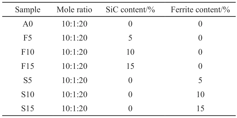
Table 2 shows the mixing ratio of magnesium oxysulfide cement based wave absorbing material samples prepared in this experiment.

Table 2 Mix ratio of magnesium oxysulfide cement based wave absorbing material samples
Firstly, the absorbent was dispersed in magnesium sulfate solution by ultrasonic wave.In the experiment,the molar ratio ofn(MgO) :n(MgSO4) :n(H2O) was determined as 10:1:20, and all kinds of materials were mixed into the blender, and the citric acid with 1%magnesium oxide content was added as the modifier,and then placed in the mold to form.After a short time of standing and foaming to the ideal height, the temperature was (24±2) ℃.After curing for 28 days under the condition of (70±5) % humidity, the wave absorbing performance was tested, (180 mm×180 mm× 30 mm used for absorbing waves).
2.3 Mineral phase and microstructure detection
The samples were crushed, dried in an oven at 60℃ for two hours, and then ground to powder.The type and crystal morphology of the experimental samples were detected by means of SEM and energy spectrum analysis.The magnification ranged from 500 to 10 000;A vector network analyzer (HP8510B) was used to test the reflectance of the absorbent material in the frequency range of 26.5-40 GHz.
2.4 Wave absorption performance test
The absorption effect of materials on electromagnetic waves is represented by reflectance, which is defined as the ratio of reflected power in the mirror direction between the absorbing material plane and the good conductor plane of the same size when the electromagnetic wave is incident on the absorbing material plane and the good conductor plane from one direction with the same power density under the condition of given wavelength and polarization.At present, there are two methods of direct measurement and indirect measurement to characterize the absorbing properties of materials.Direct measurement is a method that either directly measures the reflectance or calculates the reflectance from the test data using simple calculations.This experiment used the bow method test.
The bow method is a widely used method to test the absorbing properties of materials.It was invented by the United States Naval Laboratory in the 1940s,and the bow method test system was established in China in the 1980 s.The test system is shown in Fig.3.The bow method is mainly a test system composed of bow device, signal source, network analyzer and other equipment to measure the power of the electromagnetic wave reflected back by the standard plate (good conductor) and sample placed on the sample table to calculate the absorbing performance of the material.The bow method can be measured in a general laboratory without the need for a microwave anechoic chamber, which makes it widely used in scientific research.This experiment used the corresponding measurement parameters of 26.5-40 GHz.

Fig.3 Schematic diagram of reflectivity test by bow method
3 Results and discussion
3.1 Calculation of wave number and reflectance in the absorbing matrix
3.1.1 Calculation of wave number and reflectance
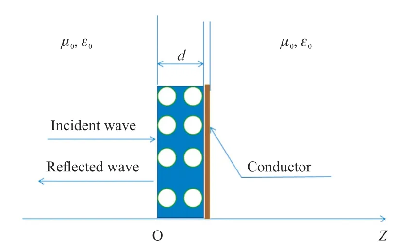
Monolayer plate material is the most simple absorbing material and the path of electromagnetic wave perpendicular incident on the surface of monolayer plate material is not complicated.The schematic diagram of the single-layer plate material is shown in Fig.4.

Fig.4 Schematic diagram of the single-layer plate material
Electromagnetic waves are reflected many times on the two surfaces of single-layer materials, and the reflectance curve of single-layer lossive materials often contains multiple interference absorption peaks[23-25].The size of the absorption peaks is related to the wavelength of electromagnetic waves and the properties of electromagnetic parameters of materials.
where, ε and μ are complex permittivity and complex permeability, respectively; εrand μrare relative complex permittivity and relative complex permeability, respectively; ε′and μ′ are the real parts of relative complex permittivity and relative complex permeability, respectively.ε"and μ"are the imaginary parts of relative complex permittivity and relative complex permeability, respectively, which reflect the ability of electrical and magnetic losses.
If the absorption peak in the reflectance curve is a coherent peak, the matching frequency of the absorption peak is obtained when the electromagnetic wave is incident vertically on the loss-material surface of a monolayer plate andfmcan be derived from the thickness of the materialdm[26].The wave velocity can be derived from the approximation of the frequency intervals of adjacent peaks and the approximation forVmis
Thus, the refractive index of the composite is
The input impedance can be calculated from the electromagnetic parameters of the medium.When the magnetic loss is ignored and assumed μr= μ′=1, the input impedance value can be converted to
Among them,Z0is the free-space impedance,the value of 120π ≈ 377Ω, and we can obtain by the index of refraction,
The wavelength in an absorbing material λmcan be extrapolated
3.1.2 Mechanism of absorption characteristics
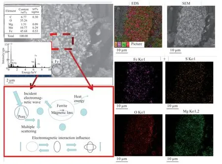
The mechanism of absorption characteristics includes dielectric loss, coherence attenuation and scattering attenuation[27], as shown in Fig.5 When an electromagnetic wave is incident on the surface of a material, part of the electromagnetic wave is reflected and another part is transmitted into the material.

Fig.5 Plot of wave absorption diagram of foam plate material
Part of the electromagnetic wave inside the channel material reaches the bottom of the material and is reflected by the bottom.
The electromagnetic wave is not completely lost when it passes through the interior of the material again and the remaining part passes through the surface and reflects with the surface interfered with each other and produces coherent absorption peaks.The ferrite and silicon carbide mixed in the foam have conductivity and high dielectric loss.Under the excitation of electromagnetic wave, polarization or induced current will occur, which will convert electromagnetic energy into heat energy and produce dielectric loss.The mismatched impedance of the interface results in scattering and reflection of waves between particles.There is a coherent attenuation between these electromagnetic waves during scattering and reflection.Therefore, the electromagnetic parameters and internal structure of the absorbing material will affect the absorbing performance of the material.
3.2 Wave absorption performance analysis
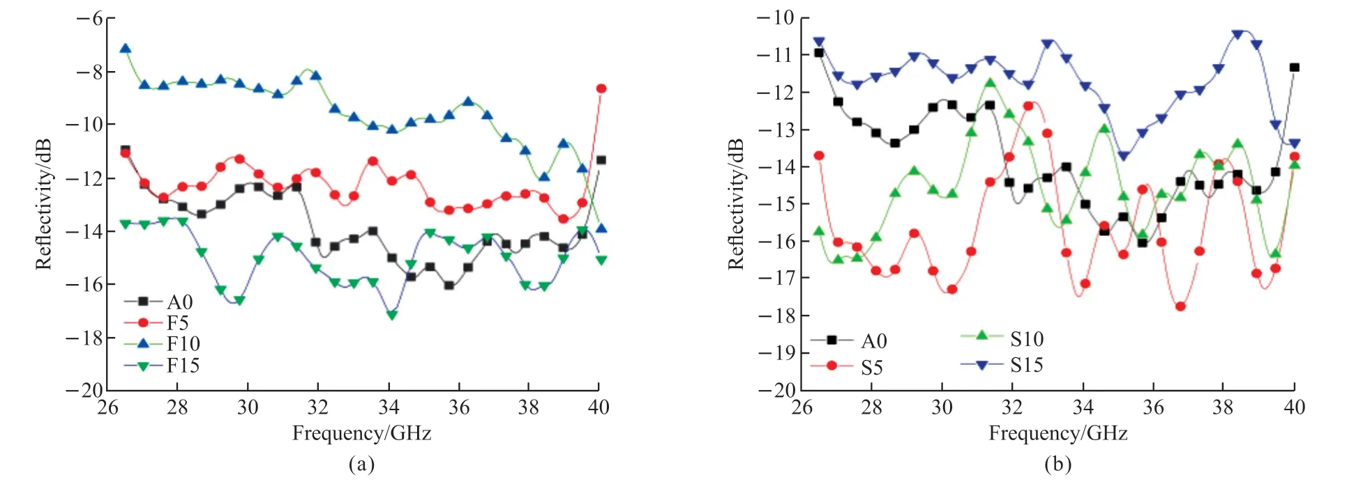
Different curves show the reflectance of materials with different incorporation amounts.Fig.6 shows that each sample of reflectance curve has a few absorption peaks, and every curve in the figure has more obvious correlation peak.For the materials through wave performance is enhanced, the electromagnetic wave is much easier to enter and penetrate materials.A second reflection wave and a reflected wave interference occurs.There is an obvious coherent absorption peak on the reflectance curve, and the reflectance of the absorption peak is determined by the amplitude and phase difference of the two reflected waves.

Fig.6 Wave absorption properties of a cement foam plate with different mixed amounts of magnesium sulfur oxide
The analysis method described in Section 3.1 can be used.The approximate velocity and refractive index are calculated by Eqs.(4) and (5), and the calculation results are summarized in Table 3.The average wave velocity can be obtained from sample S5 curve (1.53×10⁸m/s).Corresponding to Table 4 is the average value of wave velocities in all samples after removing outliers.The first three results are credible.According to Eq.(7), the order of material impedance is F15 > F10 > F5 > A0 and S15 > S10 > S5 > A0,which can be inferred from the order of impedance.The electromagnetic wave can easily penetrate the modified magnesium oxysulfide cement based foam absorbing plate filled with a small amount of ferrite.The lowest reflectance of the material can be reached at 34.1 GHz, which is -17.9 dB, and the average reflectance of the whole band is -15.9 dB.The lowest reflectance is -17.3 dB at 36.4 GHz and the average reflectance is -14.3 dB for the whole band.When the content increases, it will cause strong internal capacity consumption, and then improve the corresponding absorbing capacity.

Table 3 The electromagnetic wave velocity in the materials calculated from sample S5 curve

Table 4 The wave velocity and refractive index in different magnesium oxysulfide foam plates
3.3 Analysis of the change trend of refractive index
The trend of the calculated refractive index of the material as a function of particle size is very special.It is found from Table 4 that the refractive index of the material decreases with the increase of the incorporation amount.
According to the principle of impedance matching,improving the degree of impedance matching between material and free space can reduce the reflection of electromagnetic wave on the surface of material, which can effectively enhance the absorbing performance of material.When an electromagnetic wave is incident on the surface of a material, part of the electromagnetic wave is reflected and another part is transmitted into the material.Part of the electromagnetic wave inside the channel material reaches the bottom of the material and is reflected by the bottom.This part of electromagnetic wave is not completely lost when it passes through the material again, and the remaining part passes through the surface and interferes with the reflected electromagnetic wave, and produces a coherent absorption peak.The amount of electromagnetic wave in each part is determined by the impedance and loss capacity of the material.
3.4 Electron microscopy analysis
The following figure shows the SEM images of magnesium oxysulfide cement foam board with 5%silicon carbide and 15% ferrite.
According to Fig.7 and Fig.8, it can be seen that in a cement matrix with aperture, compared to the density of the cement matrix, a large number of aperture will combine their own storage and discharge capacity to improve the cement base material with air medium electromagnetic wave impedance matching.

Fig.7 SEM picture of magnesium sulfur oxide cement foam plate with 5% silicon carbide content

Fig.8 SEM picture of magnesium sulfur oxide cement foam plate with 15% ferrite
Silicon carbide can improve dielectric constant and resistivity of sulfur oxide magnesium cement foam board of enhancing the ability of electromagnetic waves of the dielectric loss and resistance loss.Ferrite can improve the permeability of cement, the ability of the electromagnetic interaction matrix of electromagnetic and eddy current loss, after joining ferrite (Fig.8).517 phase distribution is more dense.The ferrite particles are distributed on the corresponding pores and surfaces,so that ferrite and 517 phase are interdependent and cooperative, and good microwave absorption is obtained.
4 Conclusions
Foamed magnesium oxysulfide cement based plate has smaller dielectric constant, larger wave speed and larger impedance, which is more suitable for adding wave absorbing materials to improve impedance matching.
Silicon carbide can improve the dielectric loss and resistance loss ability of cement matrix to electromagnetic wave, and ferrite can improve the permeability of cement matrix and enhance the electromagnetic interaction ability and eddy current loss ability of matrix to electromagnetic wave.
Adding ferrite and silicon carbide can improve the absorption performance of the foam board in different degrees.When 5% silicon carbide and 15% ferrite are added, the improvement of the absorption performance of the foam board is more obvious, and the lowest average reflectance of the material can be reached by adding 5% silicon carbide.The lowest average reflectance of -14.3 dB was achieved by adding 15%ferrite.
Conflict of interest
All authors declare that there are no competing interests.
杂志排行
Journal of Wuhan University of Technology(Materials Science Edition)的其它文章
- Effect of VEGF/GREDVY Modified Surface on Vascular Cells Behavior
- Evolution of Biofilm and Its Effect on Microstructure of Mortar Surfaces in Simulated Seawater
- Synthesis of Organic-Inorganic Hybrid Aluminum Hypophosphite Microspheres Flame Retardant and Its Flame Retardant Research on Thermoplastic Polyurethane
- Surface Metallization of Glass Fiber (GF) /Polyetheretherketone (PEEK) Composite with Cu Coatings Deposited by Magnetron Sputtering and Electroplating
- Effect of Size Change on Mechanical Properties ofMonolayer Arsenene
- Effects of Sinusoidal Vibration of Crystallization Roller on Composite Microstructure of Ti/Al Laminated Composites by Twin-Roll Casting
