Hollow cathode effect in radio frequency hollow electrode discharge in argon
2024-03-25LiuLiangHe贺柳良FengHe何锋andJiTingOuyang欧阳吉庭
Liu-Liang He(贺柳良), Feng He(何锋), and Ji-Ting Ouyang(欧阳吉庭)
1College of Science,Beijing University of Civil Engineering and Architecture,Beijing 102616,China
2School of Physics,Beijing Institute of Technology,Beijing 100081,China
Keywords: hollow cathode effect, radio frequency, hollow electrode, particle-in-cell /Monte-Carlo collision(PIC/MCC)model
1.Introduction
In plasma etching process and thin film deposition process, radio frequency capacitively coupled plasma sources(RF-CCPs)are widely used due to their simple geometries.[1,2]In typical RF-CCPs, two plate electrodes are usually adopted and the electron density is generally less than 1015m-3.[3,4]However, for applications, an increase in electron density is desirable to improve etching rate and deposition rate.[3,5]In order to increase the electron density, several methods have been proposed,e.g.utilizing very high driving frequencies,[2,6]or employing magnetic fields.[7-10]Although the electron density can be increased by utilizing these methods, new problems still exist, and plasma non-uniformity occurs in plasma processing when a very high driving frequency is utilized.[11]With very high driving frequencies, electromagnetic effects,such as the standing wave effect[12-15]and skin effect[16,17]become evident and cause nonuniform plasma density,which can be important limitations for plasma processing.However,with a lower frequency(e.g.,13.56 MHz),the problem of nonuniform plasma density,caused by the standing wave and skin effect, can be avoided.[18]Therefore, if high-density plasma can be obtained at lower frequencies(e.g.,13.56 MHz),it will be very beneficial to the processes of ion etching and thin film deposition.
It has been found that RF-CCP with a hollow electrode can produce high-density plasma at a lower frequency(e.g.,13.56 MHz).[11,18-23]Hollow electrode,which typically consists of hollow cylindrical electrode or rectangular electrode, is widely utilized in direct current (DC) discharge and RF discharge.[24,25]Compared with the conventional parallelplate structure,the cavity structure reduces the loss of charged particles.[26]Depending on the operating conditions,energetic electrons are electrostatically confined inside the cavity and oscillate back and forth between opposite side walls (pendular motion), and the oscillation behavior of electrons inside the cavity is called the hollow cathode effect (HCE).[25,27,28]Comparing with parallel-plate structure, energetic electrons will suffer more inelastic collisions in the cavity due to the HCE,[27]hence ionizations and electron densities in the cavity increase.[21]
Due to the close correlation between the production of high-density plasma and the HCE, the HCE turns important in all hollow electrode discharges.Researchers have found that the HCE can be maintained and enhanced by adjusting the plasma properties.[29]It was also found that through the HCE, electrons can gain high energy in the cavity during the hollow electrode sheath’s expansion phase,and these energetic electrons pushed out of the cavity by the expanding sheaths will increase the plasma density outside the cavity,[4,11]which is beneficial for plasma etching process and thin film deposition process.However, until now, there are few studies on the HCE during the hollow electrode sheath’s collapse phase,hence it is unclear whether the hollow electrode sheath’s collapse phase contributes to increase plasma density.Zhanget al.[30]concluded that HCE cannot exist when the RF voltage on the hollow electrode is positive.However, excitations in the center of the cavity were observed to be higher than that above the planar part of the hollow electrode when a positive peak RF voltage is applied to the hollow electrode,[31]which implies that the HCE can exist in the hollow electrode sheath’s fully collapsed phase.
In this work, a two-dimensional (2D) PIC/MCC simulation is adopted to study the variations of the HCE in RF hollow electrode discharges.The rest of this paper is organized as follows.The 2D PIC/MCC model is introduced in Section 2.The simulation results are presented in Section 3.Finally,the conclusions are drawn from the present study in Section 4.
2.Description of model
The reactor geometries used in the simulation are shown in Fig.1.The cylindrical hollow electrode is connected to a 13.56-MHz RF source,while the plate electrode is grounded.The RF voltage amplitudeVRFon the hollow electrode is 210 V, and a DC bias voltageVDC=-30 V is also applied to the hollow electrode.The internal diameterDof the hollow electrode varies from 4 mm to 20 mm in the simulation,with an invariant depthh=15 mm.Both of the electrodes have a radiusrof 16 mm,with the electrode gapd=10 mm.The working gas is pure argon with pressurep= 1 Torr,(1 Torr=1.33322×10²Pa).A cylindrical coordinate system is adopted due to the axis-symmetric discharge system, and the simulation area is half of the discharge device(the red dashed line area in Fig.1).The coordinate origin(Z=0,R=0)is located in the center of the orifice,whileZ >0 andZ <0 refer to the axial positions inside and outside the cavity,respectively.
The XOOPIC code is utilized in the simulation, which is an object-oriented 2d3v(two-dimensional coordinate space and three-dimensional velocity space) PIC-MCC code.[32-35]A detailed description of this model can be found in our previous work,[36]hence in this work the model is described only briefly.Electron and argon ion(Ar+)are the main particles in the simulation.The initial distributions of electrons and argon ions in the discharge space are uniform,their temperatures beingTe=2 eV andTi=0.04 eV,respectively.The background gas argon is assumed to have a temperature of 0.04 eV and a constant density.The time steps of electrons and argon ions are set to be 3×10-13s and 3×10-12s, respectively.The number of spatial grids is 256(R)×192(Z).
In the model, collision process and recombination process between electrons and argon ions are not considered due to the low ionization degree in RF-CCPs.Electron-neutral particle collisions include elastic, excitation, and ionization collisions, and their collision cross sections can be found in Ref.[37].Ion-neutral particle collisions include elastic collisions and charge-exchange collisions,and their collision cross sections are cited from Ref.[38].Similar collision processes were considered in other PIC simulations of RF-CCPs with hollow electrodes.[27,30,31]In this work, the secondary electron emission coefficientγAr+of ions bombarding the electrode surface is set to be 0.1, and the initial energy of secondary electrons is set to be 1 eV.The computation is carried out on an Intel i3-3240 CPU machine with 4 GB of RAM and running at a clock speed of 3.4 GHz.And the simulation time is about 15 days under given conditions.
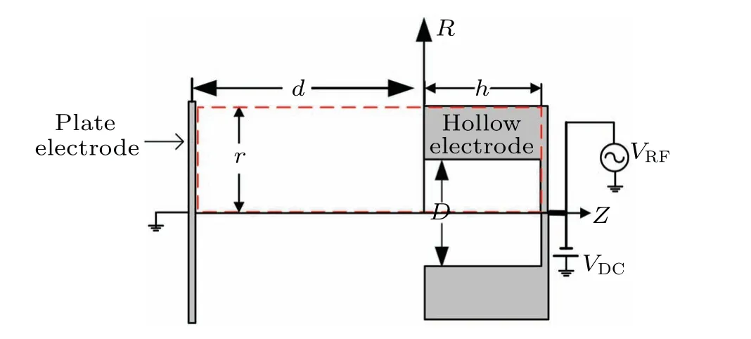
Fig.1.Schematic diagram of RF hollow electrode discharge model.
3.Results
3.1.Plasma density profiles
Figure 2 shows the spatial distributions of the timeaveraged electron density with different values of cavity diameterDof 4 mm-20 mm.And each distribution is averaged over ten RF periods after the discharge has become stable.With a small cavity diameterD=4 mm,the plasma is mainly located outside the cavity,and the electron density is the lowest.WithDincreasing to 7 mm,the electron density near the orifice increases significantly, and part of the peak electron density is located in the center of the cavity,indicating the formation of the HCE.[30]Further increasingD,the electron density inside the cavity gradually decreases,indicating that the HCE is gradually attenuated.[18]Similar variations of the electron density inside the cavity with the cavity diameter were also observed in the fluid simulations of RF hollow electrode discharges.[39]Since the HCE is the strongest withD=7 mm,in the followingD=7 mm is chosen to investigate the variations of the HCE within one RF period.
Figure 3 shows the spatiotemporal distributions of the electron density within one RF period after the discharge has become stable.In order to make the variations between the individual components more distinct, horizontal and vertical yellow dashed lines are drawn in Fig.3.Atωt/2π=0, the RF voltage on the hollow electrode reaches a positive peak value of 210 V,and the sheath inside the hollow electrode cavity is fully collapsed.While atωt/2π=0.5, the sheath inside the cavity is fully expanded.Asωt/2πvaries from 0 to 0.5 within one RF period, sheath inside the hollow electrode cavity expands.As shown in Fig.3, during the hollow electrode sheath’s expansion phase, electrons inside the cavity move to the grounded electrode for a certain distance,and the volume of electrons in the cavity is significantly reduced.As also shown in Fig.3,atωt/2π=0,part of the peak electron density is located in the center of the cavity, which indicates that the HCE exists at the fully collapsed phase of the hollow electrode sheath.In the following, we will study the variations of the HCE during the hollow electrode sheath’s expansion phase and collapse phase by investigating the sheath electric field, the sheath potential drop, the sheath thickness,the radial plasma bulk width, the electron energy distribution function (EEDF), and the average electron energy inside the cavity within one RF period.

Fig.2.Time-averaged electron density profiles with cavity diameter D=4 mm,7 mm,10 mm,15 mm,and 20 mm,with unit of electron density being m-3.

Fig.3.Spatiotemporal distributions of electron density in RF hollow electrode discharge in one RF period,with unit of electron density being m-3 and cavity diameter of hollow electrode D=7 mm.
3.2.Sheath dynamics
3.2.1.Sheath dynamics during hollow electrode sheath’s expansion phase
Figure 4 shows the spatial distributions of the radial electric field at different times ofωt/2π=0.08,0.25,and 0.42 in one RF period during the hollow electrode sheath’s expansion phase.As can be seen from Fig.4, the radial sheath electric field in the cavity gradually increases.
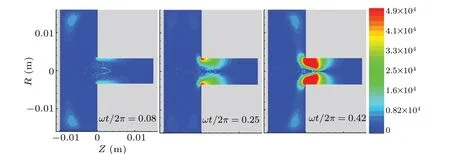
Fig.4.Spatial distributions of radial electric field at different time of ωt/2π =0.08,0.25,and 0.42 in one RF period during hollow electrode sheath’s expansion phase,with unit of electric field being V·m-1.
Figures 5(a)-5(d) show the variations of the peak radial sheath electric field, the radial sheath potential drop, the radial sheath thickness, and the radial plasma bulk width in the cavity during the hollow electrode sheath’s expansion phase.The radial sheath potential drop in the cavity is the potential difference between the potential at the sheath edge and the potential on the hollow electrode, while the selection of the instantaneous position of the radial sheath in the cavity is referred to Ref.[27].In Figs.5(a)-5(d), the axial positionZ=0.3 mm is chosen to present all the radial distributions,since the maximum electron density is obtained atZ=0.3 mm withD=7 mm.As shown in Figs.5(a)-5(c),during the hollow electrode sheath’s expansion phase,the peak electric field of radial sheath, the potential drop of radial sheath, and the radial sheath thickness in the cavity gradually increase withωt/2πincreasing.Atωt/2π=0,the radial sheath thickness is about 1.75 mm,and it increases to 3.38 mm atωt/2π=0.5.However,the radial plasma bulk width in the cavity decreases monotonically as shown in Fig.5(d).The radial plasma bulk width in the cavity decreases from 3.50 mm to 0.24 mm during the hollow electrode sheath’s expansion phase.

Fig.5.Inside the cavity during hollow electrode sheath’s expansion phase,(a)peak radial sheath electric field(at Z=0.3 mm)versus ωt/2π,(b)radial sheath potential drop(at Z=0.3 mm)versus ωt/2π,(c)radial sheath thickness(at Z=0.3 mm)versus ωt/2π,and(d)radial plasma bulk width(at Z=0.3 mm)versus ωt/2π,with cavity diameter of the hollow electrode D=7 mm.
3.2.2.Sheath dynamics during hollow electrode sheath’s collapse phase
Asωt/2πvaries from 0.5 to 1 in one RF period,sheath in the hollow electrode cavity collapses.Figure 6 shows the spatial distributions of the radial electric field atωt/2π=0.58, 0.75, and 0.92 in one RF period during the hollow electrode sheath’s collapse phase.As shown in Fig.6,the radial sheath electric field in the cavity decreases gradually.
During the hollow electrode sheath’s collapse phase, the peak radial sheath electric field, the radial sheath potential drop,and the radial sheath thickness in the cavity gradually decrease as shown in Figs.7(a)-7(c).However, the radial plasma bulk width in the cavity gradually increases withωt/2πincreasing,as shown in Fig.7(d).

Fig.6.Spatial distributions of radial electric field at ωt/2π =0.58,0.75,and 0.92 in one RF period during hollow electrode sheath’s collapse phase,with unit of electric field being V·m-1.
Fig.7.(a)Peak radial sheath electric field(atZ=0.3 mm)versusωt/2π,(b)radial sheath potential drop(atZ=0.3 mm)versusωt/2π,(c)radial sheath thickness (atZ=0.3 mm) versusωt/2π, and (d) radial plasma bulk width (atZ=0.3 mm) versusωt/2π, in the cavity during hollow electrode sheath’s collapse phase,with cavity diameter of the hollow electrodeD=7 mm.
3.3.HCE variation law
The results in Subsection 3.2 show that in RF-CCPs with hollow electrode,the sheath electric field,the sheath potential drop, the sheath thickness, and the radial plasma bulk width in the cavity vary withωt/2πin one RF period.In a DC hollow electrode discharge, the voltage on hollow electrode keeps constant, hence electric field and sheath in the cavity keep constant as well,and so does the intensity of the HCE.In an RF hollow electrode discharge, the electron pendular motion takes place under the environment of periodic variations of high-frequency electric field and sheath,hence the intensity of the HCE might vary in one RF period.
In RF-CCPs,electron heating is very important to understand the way of electron energy absorption.Secondary electron heating and sheath oscillation heating are primary electron heating mechanisms in an RF-CCP.[40]Secondary electron heating is that secondary electrons emitted from electrodes can be accelerated in the sheath and enter the plasma bulk with substantial energy.While sheath oscillation heating is a collision-free stochastic heating arising from electron interaction with the oscillating plasma boundary sheath.The variations of electric field and sheath in the cavity in one RF period cause the electron heating and the HCE to change,since the HCE is sustained by the electron heating.[27,41]It has been confirmed that both the sheath oscillation heating and secondary electron heating are important in maintaining the discharges under the simulated conditions in this work.[36]In the following, the variation of the HCE in one RF period is analyzed in detail.
3.3.1.HCE variation law during hollow electrode sheath’s expansion phase
During the hollow electrode sheath’s expansion phase(ωt/2π=0-0.5), the radial sheath electric fields and potential drops in the cavity gradually increase,and secondary electrons accelerated in the sheath can gain more energy, hence the secondary electron heating is gradually enhanced.And the calculation results of EEDF and average electron energy can also confirm the above conclusions.The EEDF is obtained by calculating the energy of electrons in the local radial sheath region or the local plasma bulk region at the corresponding time over 20 RF periods after the discharge has become stable.
Figure 8(a) shows the variations of EEDF in the radial sheath region during the hollow electrode sheath’s expansion phase.Atωt/2π=0.08,the hollow electrode sheath expands from a fully collapsed phase, and electrons in the sheath region are mainly low-energy electrons with an energy range of 0 eV-5 eV,hence the secondary electron heating is weak.Atωt/2π=0.25,energetic electrons with energy over 15.76 eV(the first ionization energy of argon atom)appear in the sheath region, and the number of low-energy electrons with energy in a range of 0 eV-5 eV decreases significantly,indicating the enhanced secondary electron heating in the sheath region.Atωt/2π=0.42,the number of energetic electrons in the sheath region increases, and the energy of some energetic electrons even reaches 30 eV, indicating that the secondary electron heating in the sheath region is further enhanced.
During the hollow electrode sheath’s expanding phase,the average electron energy in the sheath region gradually increases as shown in Fig.8(b), which can further prove that during the hollow electrode sheath’s expansion phase,the secondary electron heating is gradually enhanced.
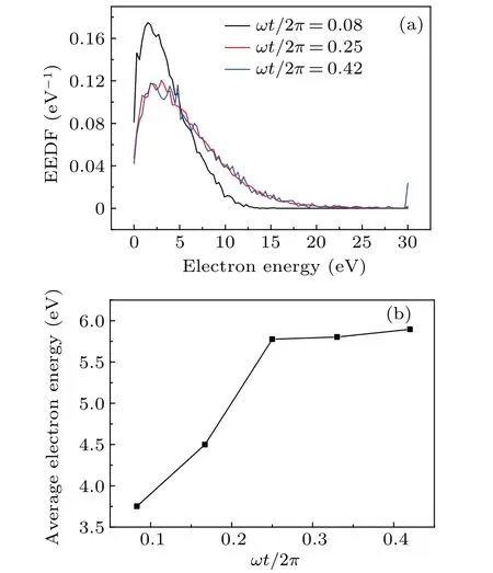
Fig.8.(a)EEDF and(b)average electron energy versus ωt/2π in radial sheath region during hollow electrode sheath’s expansion phase.
When secondary electrons are accelerated in the sheath,a lot of ionization occurs in the sheath,yielding numerous subelectrons.[21]These sub-electrons accelerated in the sheaths can also gain high energy and generate more sub-electrons,forming ionization avalanches.Due to the gradually enhanced secondary electron heating, the ionization avalanches in the sheath are also gradually enhanced, resulting in generating more high-energy sub-electrons.These high-energy secondary electrons and sub-electrons enter the plasma bulk and oscillate back and forth between the side walls(pendular motion), enhancing the HCE.In addition, with the gradually increase of radial sheath electric field in the cavity(see Fig.4),the sheath oscillation heating in the cavity is gradually enhanced, and electrons interacting with the oscillating plasma boundary sheath can gain more energy, which can enhance the HCE further.Furthermore,due to the gradual decrease of the radial plasma bulk width in the cavity(see Fig.5(d)), the path for one energetic electron to undergo a pendular motion becomes shorter, and the frequency of the electron pendular motion turns higher,[30]which can also gradually enhance the HCE.Therefore, during the hollow electrode sheath’s expansion phase,the HCE is gradually enhanced.
Figure 9(a) shows the variations of EEDF in the plasma bulk region inside the cavity during the hollow electrode sheath’s expansion phase, which can also confirm the gradually enhanced HCE.Atωt/2π=0.08,the number of electrons with energy exceeding 15.76 eV is very small,hence the HCE is weak.Atωt/2π=0.25,the number of energetic electrons with energy exceeding 15.76 eV increases, and the energy of some electrons reaches 20 eV, indicating that the HCE is enhanced.Atωt/2π=0.42, the number of energetic electrons with energy exceeding 15.76 eV further increases,and the energy of some electrons even reaches 30 eV,indicating that the HCE is further enhanced.In addition, the average electron energy in the plasma bulk region also increases during the hollow electrode sheath’s expansion phase,as shown in Fig.9(b),and our simulation results are consistent with those obtained from other researchers,[11]which further indicates the gradual enhancement of the HCE inside the cavity.
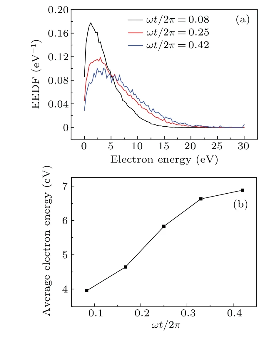
Fig.9.Variations of(a)EEDF and(b)average electron energy with ωt/2π in plasma bulk region inside cavity during hollow electrode sheath’s expansion phase.
3.3.2.HCE variation law during hollow electrode sheath’s collapse phase
During the hollow electrode sheath’s collapse phase(ωt/2π=0.5-1.0),the sheath electric field and sheath potential drop in the cavity gradually decrease (see Figs.7(a) and 7(b)),hence the secondary electron heating is gradually attenuated, which can also be confirmed by the calculation results of EEDF and average electron energy.
Figure 10(a) shows the variations of EEDF in the radial sheath region during the hollow electrode sheath’s collapse phase.As shown in Fig.10(a), the number of energetic electrons with energy exceeding 15.76 eV gradually decreases,indicating that the secondary electron heating in the sheath region is gradually attenuated.Moreover, during the hollow electrode sheath’s collapse phase,the average electron energy in the radial sheath region gradually decreases as shown in Fig.10(b), which can further prove that the secondary electron heating is gradually attenuated.
With the gradual attenuation of secondary electron heating, the ionization avalanche in the sheath is gradually attenuated, which can weaken the HCE.In addition, when interacting with the gradually collapsing sheath, the high-energy plasma bulk electrons will lose some energy, which will also weaken the HCE intensity.Furthermore, due to the gradual increase of the radial plasma bulk width in the cavity (see Fig.7(d)),the path for the electron pendular motion gradually becomes longer, and the frequency of the electron pendular motion gradually decreases,which further attenuates the HCE intensity.Therefore,during the hollow electrode sheath’s collapse phase,the HCE is gradually attenuated.

Fig.10.Variations of(a)EEDF and(b)average electron energy with ωt/2π in radial sheath region during hollow electrode sheath’s collapse phase.
Figure 11(a)shows the variations of EEDF in the plasma bulk region inside the cavity during the hollow electrode sheath’s collapse phase, which can also confirm the gradually attenuated HCE intensity.As shown in Fig.11(a), in the plasma bulk region,the number of energetic electrons with energy exceeding 15.76 eV gradually decreases, indicating that the HCE intensity is gradually attenuated.Furthermore, during the hollow electrode sheath’s collapse phase, the average electron energy in the plasma bulk region gradually decreases as shown in Fig.11(b),which can further prove that the HCE is gradually attenuated.
Due to the existence of the HCE at the hollow electrode sheath’s fully collapsed phase,it is observed experimentally that the excitation rate inside the cavity is higher than that above the planar part of the hollow electrode at the hollow electrode sheath’s fully collapsed phase.[31]And with the gradually enhancing HCE during the hollow electrode sheath’s expansion phase,the excitation and ionization inside the cavity are gradually enhanced as can be found in Ref.[31].However, with the gradually attenuating HCE during the hollow electrode sheath’s collapse phase, the excitation and ionization inside the cavity are gradually attenuated,which can also be found in Ref.[31].
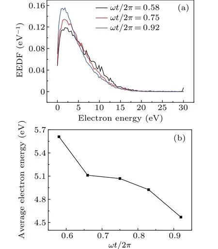
Fig.11.Variations of(a)EEDF and(b)average electron energy with ωt/2π in plasma bulk region inside cavity during hollow electrode sheath’s collapse phase.
4.Conclusions
The variations of the HCE in one RF period in RFCCP with a hollow electrode are investigated by using a 2D PIC/MCC model.It is found that the sheath electric field,the sheath potential drop, the sheath thickness, the radial plasma bulk width, the EEDF,and the average electron energy in the cavity vary in one RF period.During the hollow electrode sheath’s expansion phase,the sheath potential drop and sheath electric field in the cavity gradually increase,which can gradually enhance the secondary electron heating and sheath oscillation heating,and the enhanced electron heating can enhance the HCE.Furthermore, during the hollow electrode sheath’s expansion phase, the frequency of the electron pendular motion gradually increases, which can enhance the HCE further.Therefore, during the hollow electrode sheath’s expansion phase,the HCE is gradually enhanced.
However, during the hollow electrode sheath’s collapse phase,the sheath potential drop and sheath electric field in the cavity gradually decrease,hence the secondary electron heating is gradually attenuated, which can weaken the HCE intensity.In addition, energetic plasma bulk electrons will lose some energy during their interactions with the gradually collapsed sheath,which can attenuate the HCE intensity as well.Furthermore,the frequency of electron pendular motion gradually decreases, which can further attenuate the HCE intensity.Therefore, during the hollow electrode sheath’s collapse phase,the HCE is gradually attenuated.
猜你喜欢
杂志排行
Chinese Physics B的其它文章
- A multilayer network diffusion-based model for reviewer recommendation
- Speed limit effect during lane change in a two-lane lattice model under V2X environment
- Dynamics of information diffusion and disease transmission in time-varying multiplex networks with asymmetric activity levels
- Modeling the performance of perovskite solar cells with inserting porous insulating alumina nanoplates
- Logical stochastic resonance in a cross-bifurcation non-smooth system
- Experimental investigation of omnidirectional multiphysics bilayer invisibility cloak with anisotropic geometry
