Controllable optical bistability in a Fabry–P´erot cavity with a nonlinear three-dimensional Dirac semimetal
2024-03-25HongXiaYuan袁红霞JiaXueLi李佳雪QiJunMa马奇军HaiShanTian田海山YunYangYe叶云洋WenXinLuo罗文昕XingHuaWu吴杏华andLeYongJiang蒋乐勇
Hong-Xia Yuan(袁红霞), Jia-Xue Li(李佳雪), Qi-Jun Ma(马奇军), Hai-Shan Tian(田海山),Yun-Yang Ye(叶云洋), Wen-Xin Luo(罗文昕), Xing-Hua Wu(吴杏华), and Le-Yong Jiang(蒋乐勇)
1School of Physics and Electronics,Hunan Normal University,Changsha 410081,China
2School of Intelligent Manufacturing and Electronic Engineering,Wenzhou University of Technology,Wenzhou 325035,China
3Key Laboratory for Microstructural Functional Materials of Jiangxi Province,College of Science,Jiujiang University,Jiujiang 332005,China
Keywords: optical bistability,Dirac semimetal,Fabry-P´erot cavity
1.Introduction
Optical bistability(OB)refers to a nonlinear optical phenomenon that occurs when incident light passes through a nonlinear optical system.Specifically, it is characterized by two stable output light intensities corresponding to a given input light intensity,[1,2]and these two stable states can rapidly transition under certain conditions.[3]Its characteristic curve usually exhibits a hysteresis loop.Based on these properties, OB has been widely used in optical memory,[4]alloptical switching,[5,6]electro-optomechanical switches,[7]optical transistors,[8]and other fields.Although researchers are familiar with the relevant theory and generation mechanism of OB,the application of optical bistable devices is still subject to significant limitations.These limitations are primarily due to the huge OB threshold, which depends on the degree of nonlinear response and field localization in the nonlinear materials or structures.The nonlinear coefficient of traditional nonlinear materials is relatively low, making it difficult to generate ideal OB without a very high threshold value when using such materials.A large threshold value usually leads to damage to optical bistable devices.At the same time, traditional optical bistable devices tend to be relatively large in size, expensive and inconvenient to use,which seriously hinders the development of OB in micro-nano optoelectronic devices.To protect devices and expand their application scenario,the threshold of OB should be as low as possible.Therefore,finding new materials and structures to achieve low-threshold optical bistable devices is the focus of current research efforts.Researchers have devoted a lot of effort to the study of OB based on micro-nano structures, such as one-dimensional gratings,[9]Fabry-P´erot(FP)cavities,[10,11]Ag/dielectric multilayers,[12]photonic crystals,[13]three-mode optomechanical systems,[14]graded core-shell granular composites[15]and other micronano structures have verified the existence of OB.It is well known that localized field enhancement resulting from some optical mechanisms has a positive effect on reducing the threshold of OB.Therefore,low-threshold OB research based on localized field enhancement such as surface plasmons,[16]optical Tamm states[17]and Bloch surface waves[18]has also become a focus of attention for researchers.
In recent years, with the development of materials science, Dirac materials have gradually attracted increasing attention.Among them, three-dimensional Dirac semimetal(3D DSM) has received a great deal of attention from researchers as a member of the Dirac materials family.Similar to graphene, 3D DSM has many excellent photoelectric properties.[19]First, 3D DSM has a very high nonlinear bulk conductivity in the THz band.[20]Secondly, the carrier mobility of 3D DSM can be as high as 9×106cm2·V-1·s-1,which is tens of times that of graphene carrier mobility.[21]In addition,3D DSM is highly tolerant to environmental defects and superconductivity and,because it is massive,it is not easily disturbed by the dielectric environment, its preparation is simpler and its coupling with light is also very strong.[22]The huge third-order nonlinear bulk conductivity of 3D DSM can help to achieve low-threshold OB.At the same time, we can manipulate the nonlinear conductivity of 3D DSM by adjusting its Fermi energy and other material parameters,[23]providing a feasible path for achieving tunable OB.Based on these excellent properties,3D DSM will have greater application prospects in micro-nano optoelectronic devices than traditional linear and nonlinear materials.For example, Chenet al.proposed an absorber based on a body Dirac semimetal metasurface[24]and Yanet al.proposed a terahertz ultrasensitive sensor structure based on 3D DSM.[25]These related studies demonstrate the bright future of 3D DSM in optical bistable devices.
The FP cavity is a classic structure for implementing OB.However, a single FP cavity lacks the necessary nonlinear medium to achieve the OB phenomenon, while 3D DSM can provide nonlinear effects.Therefore, the combination of FP cavity resonance and the nonlinear conductivity of 3D DSM is an effective method to achieve low-threshold OB.Based on this, we put forward a composite structure in this article,which places 3D DSM in the FP cavity and theoretically studies the tunable OB based on this composite structure in the terahertz band.The results show that the composite structure can achieve OB,and the threshold and hysteresis width of OB are very sensitive to changes in the Fermi energy, relaxation time and thickness of 3D DSM.In addition,the cavity length also has a certain influence on the OB curve.Therefore, we can realize the tunable bistability characteristics in this structure by adjusting the relevant parameters of the 3D DSM as well as the structural parameters.This scheme has a simple structure and may promote the practical application of OB in micro-nano optoelectronic devices.
2.Theoretical model and method
We consider an FP cavity containing single-layer 3D DSM.The 3D DSM is placed in the middle of the FP cavity,and the rest of the cavity is filled with air,as shown in Fig.1.The FP cavity consists of two mirrors separated by a certain distance and parallel to each other,and the cavity length satisfiesLc=m·λ/(2na), wherena=1 is refractive index of the air andλ=300 µm (1 THz) is the incident wavelength, respectively.mrepresents an integer and we temporarily set the value to 1.Therefore, we can set the cavity length to a minimum value ofLc=150 µm.The remaining parameters are set as follows: the thickness of the 3D DSM isdD=20 nm,the transmittance of the mirrors ist2m=0.3 and the incident angle isθ=0°.After the incident lightEienters the mirror surface, the corresponding reflected beamErand transmitted beamsEtare generated, and we mainly have a series of discussions around the relationship betweenEiandEr,EiandEt.
The linear intraband optical conductivity of the 3D DSM can be obtained by using the semiclassical Boltzmann transport equation under the relaxation time approximation,and the approximate expression is[26]
whereLi2(z)denotes the natural logarithm andσ0=e2/(4ℏ).The expression for the third-order nonlinear conductivity of the 3D DSM is[26]
where ℏ is the reduced Planck’s constant,Tis the temperature,kBis the Boltzmann constant,ωis the angular frequency,vF=106m/s is the Fermi velocity,EFis the Fermi energy of the 3D DSM,andτis the relaxation time of the 3D DSM.The third-order susceptibility of 3D DSM is related toσ(3), and can be expressed as
Based on the third-order susceptibility,it is convenient to represent the nonlinear refractive index of 3D DSM.[26]Meanwhile,the linear refractive index of the 3D DSM is a complex number and can be expressed as
whereε0denotes the vacuum permittivity.Strictly speaking,based on the calculation formula of the total refractive index,and after considering the nonlinear refractive index of 3D DSM, the total refractive index of 3D DSM should be constantly changing with the direction of the incident light.Because the intensity of the incident light in the propagation direction will transform with the change of the position,causing the total refractive index to change accordingly.However,we neglected this change,which meant we approximately thought that the nonlinear refractive index of 3D DSM did not change with the direction of transmission light throughout the whole nonlinear 3D DSM.That is mainly because the thickness of the 3D DSM here is very thin (20 nm), and the change in light intensity at this thickness is very small or even negligible.Therefore, such an approximation has little effect on the correctness of the calculated results.It can be seen from Eqs.(3)and(4)thatχ(3)andndof the 3D DSM are closely associated with the linear and nonlinear conductivities of the 3D DSM,and the conductivity of the 3D DSM can be tuned by adjustingEFandτ.Therefore,we can flexibly manipulate the OB curve by adjusting the values ofEFandτ, so as to achieve tunable OB.tionship between two adjacent layers by specific expressions,for the entire structure,the transformation matrix of the entire structure is very complex,which cannot be reflected as a clear and simple expression but can only be displayed in the form of numerical calculation.Using this method, we can easily obtain the transmittance and reflectance of the layered structure.For a general multilayer structure,we only need to know the refractive index and thickness of each layer to express the transfer matrix of each layer.[27]Here, we only consider the transverse electric polarization case to simplify calculations.First,the transfer matrix of air can be expressed in terms of its thickness and refractive index as
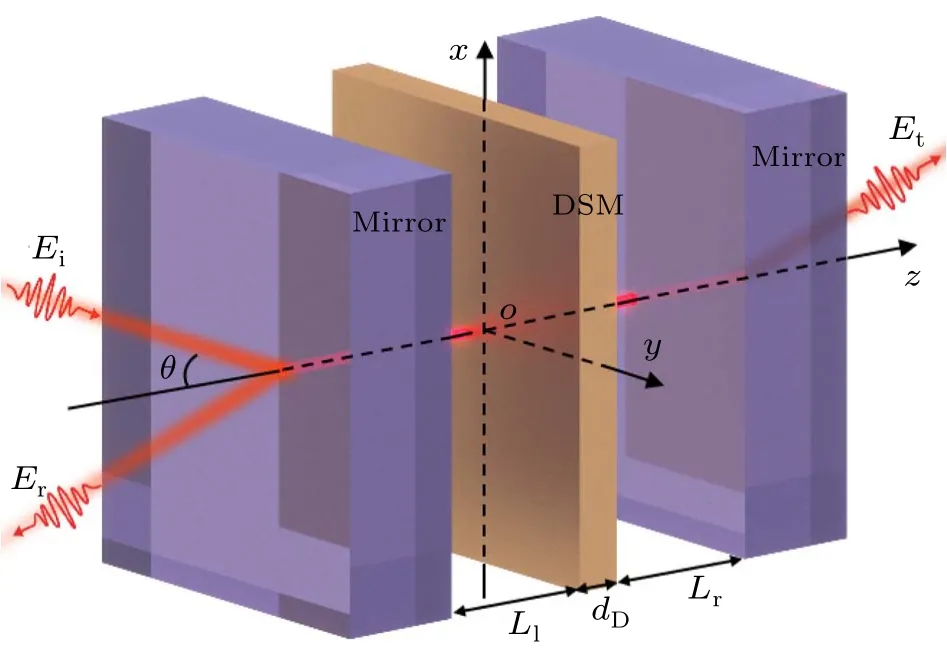
Fig.1.Schematic representation of the composite structure of the 3D DSM embedded in the FP cavity.
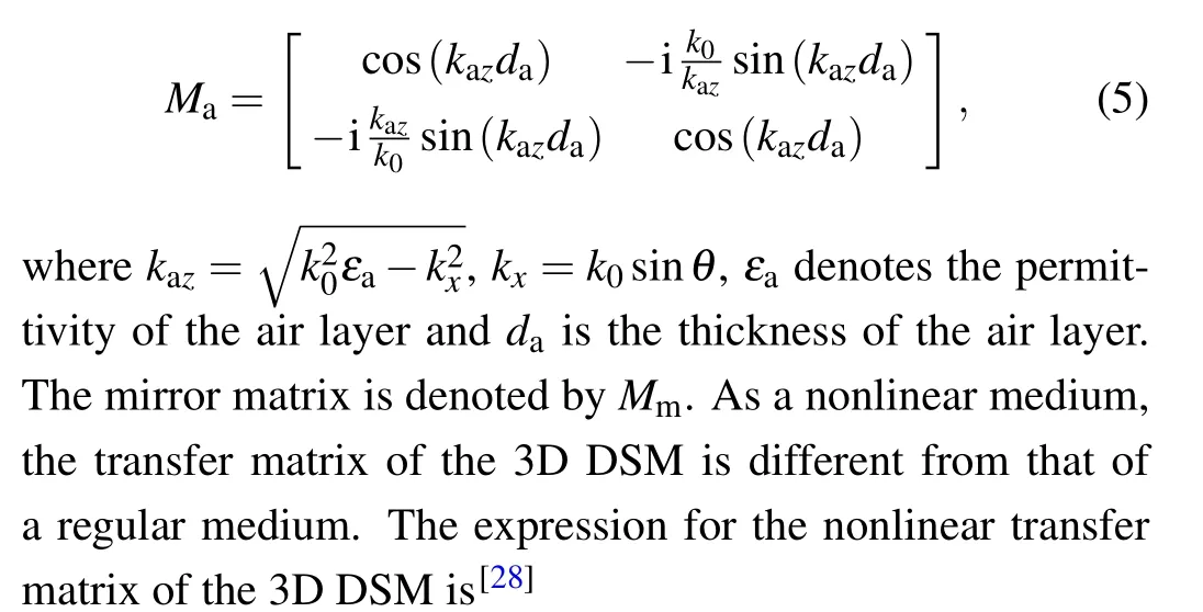
We use the transfer matrix method to calculate the transmittance and reflectance of the entire multilayer structure.It is known that the transfer matrix method can relate the electromagnetic field distributions of adjacent media in a layered structure.For simple multilayer structures (e.g., one or two layers), the transformation matrix can easily derive very explicit expressions.For multilayer structures, although it can be easy to obtain the electric field and magnetic field rela-
wherekd+andkd-are the wave vectors of the forward propagating waves and backward propagating waves,respectively,and can be expressed as
here,A+andA-are the amplitudes of the forward and backward propagating waves, respectively, andndis the linear refractive index of the 3D DSM.In our calculation, we set and find the stable solution using the fixed-point iteration method,[29]and then obtain the nonlinear transfer matrixMDusing Eqs.(7)and(8).Therefore,we can simply get the transfer matrix of the entire multilayer structure,specifically:
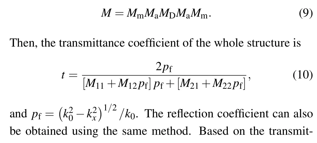

It should be pointed out that the dependence of the transformation matrix on the display of nonlinearity cannot be clearly demonstrated in an analytic form.After all, the nonlinear third-order susceptibility of the medium is reflected in the nonlinear transmission matrix of the nonlinear medium through relatively complex expressions.The resulting nonlinear relationship can only be demonstrated numerically, which is the approach used in many works involving OB.
3.Results and discussion
In the previous section,we mainly introduce the calculation method for OB.In this section,we first discuss the impact of introducing 3D DSM on the transmittance and reflectance of the FP cavity.When calculating the transmittance and reflectance, we only considered the linear part of the conductivity of 3D DSM.Using the transfer matrix method,[30]we have plotted the transmittance and reflectance as a function of frequency with and without 3D DSM,while also demonstrating the effect ofEFon the transmittance and reflectance of the structure, as shown in Fig.2.The solid line represents the transmittance of the structure, and the dotted line represents the reflectance of the structure.The green lines in Fig.2 represent the transmittance and reflectance of the structure when 3D DSM has not been added.As can be seen from the green solid and dotted lines, when the FP cavity is empty, the transmittance and reflectance of the structure can almost reach 100%at 1 THz.This phenomenon is closely related to the resonance mode of the FP cavity.However,with the addition of 3D DSM,the transmittance and reflectance curves clearly experience a blue shift,and the peak values also decrease.Moreover,asEFgradually increases,the blue shift phenomenon becomes more pronounced, and both the transmittance and reflectance peaks move towards higher frequency.From Fig.2 we can see that the addition of 3D DSM has a great impact on the transmittance and reflectance of the entire structure.At the same time,EFalso has a certain influence on it.Thus, we can easily control the transmittance and reflectance by manipulating the Fermi energy of the 3D DSM, which provides a feasible scheme for achieving tunable OB.

Fig.2.Reflectance and transmittance as a function of frequency.
We already know that the addition of 3D DSM has a significant impact on the entire structure.Then, we discuss the effect ofEFon the OB curve in the terahertz band.Here,combined with the structural parameters of the FP cavity, we fix the frequency of the incident light at 1 THz.According to formula(2),we can see that the nonlinear conductivity of 3D DSM in the terahertz band is very large.Furthermore,the resonance of the FP cavity enhances the local electric field inside the cavity.For a more intuitive representation,the relationship diagrams of the transmitted electric field and the reflected electric field with the incident electric field are plotted in Figs.3(a)and 3(b), respectively.It can be seen that there is no obvious bistable phenomenon after removing the FP cavity.Therefore,the FP cavity plays a very positive role in promoting bistability.Specially, the combination of the FP cavity and the 3D DSM creates the possibility of reducing the OB threshold.It is obvious that the composite structure of FP cavity with an added 3D DSM can effectively induce both transmitted and reflected OB.Taking the green dashed S-curve in Fig.3(a)as an example, at this time,EF= 0.37 eV.First, the transmitted electric field|Et|increases as the incident electric field|Ei| increases; when|Ei| reaches a value of the upper threshold|Ei|up,|Et| suddenly jumps to a relatively high field, and then continues to increase with the increase of|Ei|.In contrast, as|Ei|gradually decreases from a relatively high value,|Et| decreases with the decrease of|Ei|; when|Ei| decreases to a value of the lower thresholds|Ei|down,|Et|also suddenly jumps to a very low value, and then decreases with the decrease of|Ei|.In addition,EFserves as an important control point for OB,and figure 3 shows the dependence of the transmitted OB and the reflected OB on the Fermi energy.Figure 3(a)mainly depicts the relationship between|Et|and|Ei|.Figure 3(b)reflects the relationship between the reflected electric field(|Er|)and|Ei|.The patterns in Fig.3(a)and 3(b)are very similar, as the Fermi energy increases from 0.34 eV to 0.38 eV in equal intervals, both|Ei|upand|Ei|downof the OB curve all gradually move toward a higher electric field,and the hysteresis loop becomes more and more obvious.To observe the influence ofEFon the width Δ|Ei|=|Ei|up-|Ei|downof the hysteresis curve more intuitively,we have plotted Fig.3(c).In Fig.3(c),asEFincreases,the width of the hysteresis curve also increases.For example,whenEF=0.35 eV,Δ|Ei|=|Ei|up-|Ei|down= 2.22×10⁶V/m; whenEF= 0.37 eV, Δ|Ei| =|Ei|up-|Ei|down= 6.48×10⁶V/m; whenEF= 0.39 eV,Δ|Ei|=|Ei|up-|Ei|down=12.83×10⁶V/m.These data are a good illustration of the law in Fig.3(c), where the smaller the value ofEF, the smaller the threshold for OB.Although the threshold of OB should be as small as possible,we can no longer observe the OB curve whenEF≤0.33 eV.This point provides an important reference for the subsequent construction of tunable bistable devices.
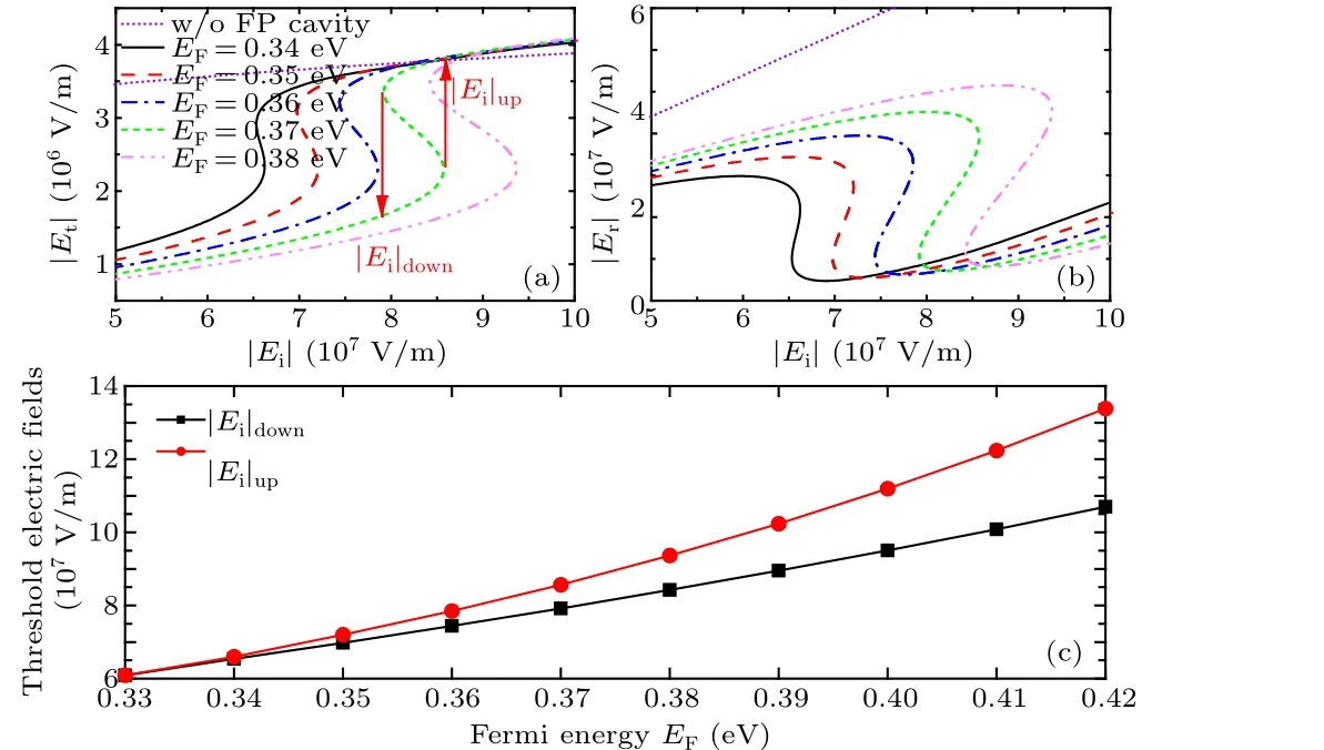
Fig.3.The influence of EF on (a) the transmitted OB; (b) the reflected OB;(c)the trend of|Ei|up and|Ei|down as a function of Fermi energy of the 3D DSM.
According to the formulas for the linear conductivity and third-order susceptibility of 3D DSM, in addition toEFbeing able to adjust the values of the linear conductivity and the third-order susceptibility,the relaxation timeτcan also have a significant effect on their values.Therefore, in our work, we also use relaxation time as a manipulation method.Using the nonlinear transfer matrix method,we draw multiple curves of|Et|and|Er|as a function of|Ei|when different values of relaxation time are taken.We first observe Figs.4(a)and 4(b)whereEF=0.34 eV,t2m=0.3,we fix other structural parameters and discuss the influence of a single variableτon the transmitted and reflected OB.It is not difficult to find that asτincreases,|Ei|upand|Ei|downof the OB curve gradually decrease.Taking the change law of the transmitted OB in Fig.4(a) as an example, whenτ=0.82 ps,|Ei|down=6.828×10⁷V/m,|Ei|up= 6.851×10⁷V/m; whenτ= 0.84 ps,|Ei|down=6.755×10⁷V/m,|Ei|up=6.785×107V/m;whenτ=0.86 ps,|Ei|down=6.675×10⁷V/m,|Ei|up=6.729×107V/m;whenτ= 0.88 ps,|Ei|down= 6.602×10⁷V/m,|Ei|up= 6.674×10⁷V/m; whenτ= 0.90 ps,|Ei|down= 6.533×10⁷V/m,|Ei|up=6.608×107V/m.Based on the above data, we conclude that within a controllable and reasonable range,a larger value of relaxation time leads to a smaller threshold of OB.Furthermore,the trend of relaxation time on the reflected OB in Fig.4(b)is basically the same as that in Fig.4(a).Therefore,controlling the value of relaxation time is also a very effective method for reducing the OB threshold.Figures 4(c)and 4(d)discuss the relationship between|Et|and|Er|as a function of|Ei| when the transmittance of the mirror takes different values.Similar to the trends in Fig.4(a)and 4(b),as the transmittance of the mirror increases,|Ei|upand|Ei|downof OB move towards lower electric fields overall.However, the change in|Ei|upand|Ei|downis almost the same,so the hysteresis width hardly changes.The results show that the transmittance of the mirror is also one of the regulation points when manipulating the OB threshold.
In addition to the parameters mentioned earlier, the cavity length of the FP cavity also has a certain influence on the threshold and hysteresis width of the OB.As the cavity lengthLcincreases from 140µm to 155µm,the threshold of the transmitted OB undergoes a significant change, and with the increase ofLc,|Ei|upand|Ei|downof the OB also shift to higher electric fields, as shown in Fig.5(a).However, under the premise ofLcmeeting the condition ofkLc=π,only small adjustments are needed.The results presented in Fig.5 show that the cavity length of the FP cavity plays a very important role in achieving tunable OB.As a stable dielectric, the thickness of the 3D DSM cannot be ignored.Therefore,when discussing the parameters that affect the threshold of the OB,we also considered the thicknessdDof the 3D DSM.The results show that, although the changes ofdDare only small,the threshold and hysteresis width of the OB still undergo significant changes, as shown in Fig.5(b).WhendDincreases from 20 nm,only 5 nm increases each time,|Ei|upand|Ei|downof the transmitted OB also increase, but the increase rate of|Ei|upis faster than that of|Ei|down, which results in an increase in the hysteresis width.Specifically,whendD=20 nm,Δ|Ei| =|Ei|up-|Ei|down= 0.089×10⁷V/m; whendD=25 nm, Δ|Ei| =|Ei|up-|Ei|down= 0.868×10⁷V/m; whendD= 30 nm, Δ|Ei| =|Ei|up-|Ei|down= 2.092×10⁷V/m;and whendD=35 nm, Δ|Ei|=|Ei|up-|Ei|down=3.690×10⁷V/m.The above calculation results demonstrate the trend of the threshold bandwidth changing withdD, indicating thatdD, as an indispensable parameter of 3D DSM, can also be a key factor in realizing tunable low-threshold OB within a reasonable range.The discussion of the above trends is very meaningful for practical experimental testing or device preparation scenarios.After all, in practical situations, precise implementation of material thickness is not an easy task,so it is necessary to clarify the impact of subtle changes in 3D DSM thickness on OB.

Fig.4.(a)and(b)Changes of transmitted OB and reflected OB at different relaxation times;(c)and(d)changes of transmitted and reflected OB when the mirror takes different transmittance.
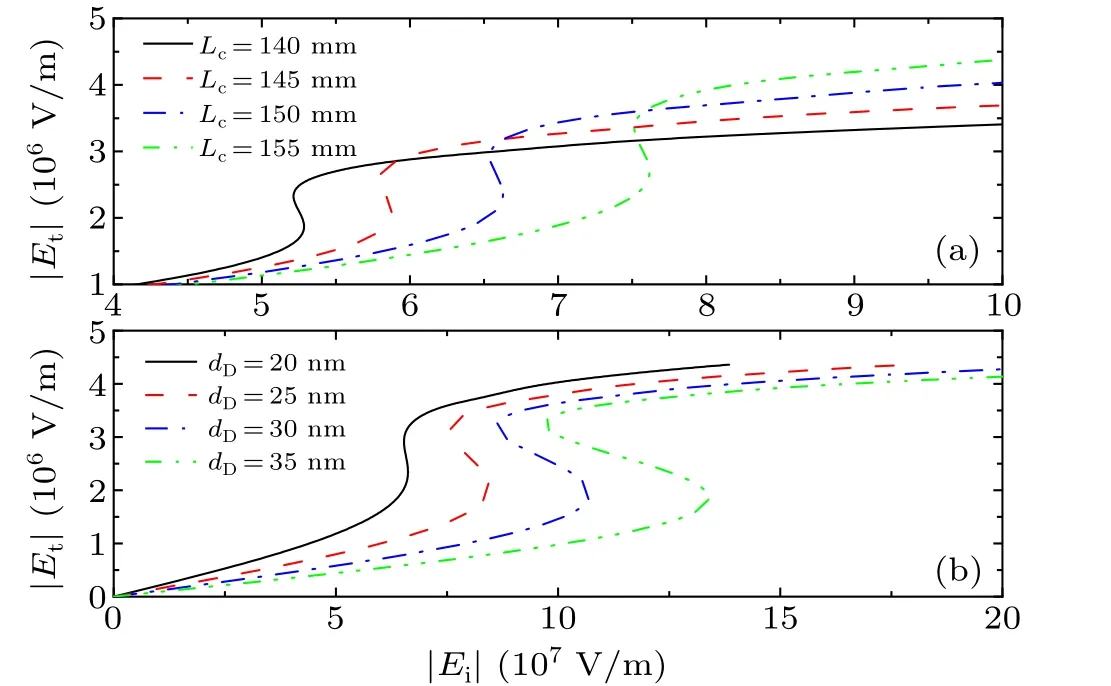
Fig.5.Dependence of transmitted OB on(a)cavity length of FP cavity;(b)the thickness of 3D DSM.
4.Conclusion
In summary, we have theoretically studied the nonlinear OB phenomenon in an FP cavity multilayer structure by inserting 3D DSM.We observed both transmitted and reflected OB phenomena.The FP cavity serves as a classical structure for exciting OB,and the cavity resonance and the nonlinear effect provided by 3D DSM are favorable conditions to achieve OB.Moreover,both the third-order susceptibility and the linear refractive index of 3D DSM can be adjusted by changing the Fermi energy and relaxation time of the 3D DSM.Therefore,both the Fermi energy and the relaxation time of the 3D DSM are crucial factors in achieving adjustable OB.Based on the above,we have mainly discussed the regulatory role of the Fermi energy and relaxation time of 3D DSM on the OB curve.In addition, it is found that OB curves are also sensitive to the thickness of 3D DSM, the cavity length of the FP cavity and the transmittance of the mirror.We believe that this tunable OB scheme could promote the potential applications of optical bistable devices based on 3D DSM in micro-nano optoelectronic devices.
Acknowledgments
Project supported by the Wenzhou Major Science and Technology Innovation Project: Research and Industrialization of Key Technologies for Intelligent Dynamic Ultrahigh Pressure Microfluidizer (Grant No.ZG2023012), Wenzhou Major Science and Technology Innovation PR Project(Grant No.ZG2022011), the National Natural Science Foundation of China(Grant No.62305254),the Scientific Research Fund of the Natural Science Foundation of Hunan Province(Grant No.2022JJ30394),the Changsha Natural Science Foundation(Grant Nos.kq2202236 and kq2202246),and the Science and Technology Project of Jiangxi Provincial Education Department(Grant No.GJJ190911).
猜你喜欢
杂志排行
Chinese Physics B的其它文章
- A multilayer network diffusion-based model for reviewer recommendation
- Speed limit effect during lane change in a two-lane lattice model under V2X environment
- Dynamics of information diffusion and disease transmission in time-varying multiplex networks with asymmetric activity levels
- Modeling the performance of perovskite solar cells with inserting porous insulating alumina nanoplates
- Logical stochastic resonance in a cross-bifurcation non-smooth system
- Experimental investigation of omnidirectional multiphysics bilayer invisibility cloak with anisotropic geometry
