On-chip ultrafast stackable dielectric laser positron accelerator
2024-03-25BinSun孙斌YangfanHe何阳帆ChenhaoPan潘晨浩SijieFan樊思劼DuWang王度ShaoyiWang王少义andZongqingZhao赵宗清
Bin Sun(孙斌), Yangfan He(何阳帆), Chenhao Pan(潘晨浩), Sijie Fan(樊思劼),Du Wang(王度), Shaoyi Wang(王少义), and Zongqing Zhao(赵宗清),‡
1Department of Plasma Physics and Fusion Engineering,School of Nuclear Science and Technology,University of Science and Technology of China,Hefei 230026,China
2National Key Laboratory of Plasma Physics,Research Center of Laser Fusion,China Academy of Engineering Physics,Mianyang 621900,China
3School of Physical Science and Technology,ShanghaiTech University,Shanghai 201210,China
4State Key Laboratory of High Field Laser Physics and Chinese Academy of Sciences Center for Excellence in Ultra-Intense Laser Science,Shanghai Institute of Optics and Fine Mechanics,Chinese Academy of Sciences,Shanghai 201800,China
5Department of Engineering Physics,Tsinghua University,Beijing 100084,China
6The Institute of Technological Sciences,Wuhan University,Wuhan 430072,China
Keywords: dielectric laser accelerator, positron accelerator, high gradient accelerator, inverse Cherenkov effect
1.Introduction
Positron accelerators have shown promising in a wide range of applications in spanning multi-scientific domains.On the one hand, high-energy positron beams have been used in several research fields.In the field of physics, high-energy positron-electron collisions provide an ideal platform to study the Higgs boson precisely and potentially discover physics beyond the Standard Model.[1,2]In medical imaging, positron accelerators are used to create positron emission tomography(PET)scans,which aid in the diagnosis and monitoring of diseases like cancer.[3,4]Nuclear physicists employ positron accelerators to study the structure of atomic nuclei and properties of nuclear matter,[5,6]while scientists utilize them to examine the structure and properties of materials.[7,8]On the other hand, the generation of sub-femtosecond bunches of energetic electrons and positrons offers significant potential from ultrafast physics to novel radiation sources.[9]However,traditional RF particle accelerators have limitations.They tend to be large, expensive, and have a threshold for metal breakdown, while their power and frequency are constrained by microwave sources.[10-13]Otherwise, during the process of laser-accelerating positrons, the temporal duration of the positron beam tends to retain that of the electron beam, typically governed by the width of the laser pulse.Achieving a sub-femtosecond level is difficult.[14-17]These difficulties restrict the applications of accelerators,which has led to research and competition among new acceleration schemes.
Several schemes for developing miniature or desktop particle accelerators have emerged in recent years.[18-21]Among them, dielectric laser acceleration (DLA) mechanisms have garnered increasing attention for their potential to facilitate the development of on-chip microscopic accelerators.Notably,two pivotal concepts within DLA have emerged: the inverse Smith-Purcell effect laser dielectric acceleration[22-27]and the inverse Cherenkov effect laser dielectric acceleration.[28-33]These concepts have been studied since the 1960s, not long after the invention of lasers,and have shown great promise as viable acceleration methods.
The stacked acceleration structure,which is based on the inverse Cherenkov effect laser dielectric acceleration principle,represents a novel design scheme that enables the cascade acceleration of low-energy positrons.This design eliminates the need for laser front tilting techniques and multiple lasers,which can be challenging to couple.[28-33]Additionally, the stacked structure facilitates higher acceleration gradients and energy gains, with no theoretical upper limit on acceleration energy.[32]Furthermore, the modular nature of this structure allows for additional configuration flexibility to meet the specific requirements of different applications.[32]In this article,we report the successful achievement of the first laser dielectric acceleration of positrons through the inverse Cherenkov effect.The stacked acceleration structure is utilized to achieve high-gradient long-range acceleration and to produce a subfemtosecond ultrafast positron beam, with the added benefit of beam quality modulation.This stacked positron accelerator represents a model for future chip-based positron accelerators.
2.Accelerator simulation design
In this study, a two-dimensional numerical simulation was performed using the finite element method (FEM) and particle-in-cell (PIC) algorithm.The structure of the simulation, as depicted in Fig.1, consists of a prism with a base angleαset to 30°, the laser is incident on a dielectric prism perpendicular to surface A.An evanescent wave is generated at surface B.This wave propagates forward along the surface in thex-direction with a velocityvw=c/(n·sinα), whereαis the angle between the hypotenuse and the bottom edge,cis the speed of light in vacuum, andnis the refractive index of the prism.As the positron moves through the vacuum channel below surface B,either the Cherenkov effect or its inverse can occur, with the occurrence of the different effects depending on the phase in which the positron is located.In addition,if the positron is to be able to continuously undergo an effect such as acceleration by the inverse Cherenkov effect,then the positron velocity must be made to satisfyvp=vw=c/(n·sinα)within a certain range.However,as the positron energy increases,the above problem is no longer satisfied.To solve it,we propose the idea of a stacked structure by changing the refractive index magnitude of each dielectric layer so thatvp=vwcan be basically satisfied.In addition, since the structure is closely arranged in layers,the length and refractive index of the subsequent layers are affected by the previous layer, and the parameter of each layer is given by the formulae
indicating that similar structures have been developed for electron acceleration.[32]The variablenirepresents the refractive index of each layer in the stacked structure.The initial refractive index, denoted asn1, is determined by the condition for the inverse Cherenkov effect, which is given byn1= (β1·sinα)-1.Here,β1andLicorrespond to the relativistic velocity magnitudes and longitudinal lengths of the respective layers.In the vacuum channel,the transverse force acting on the positron from the laser incident downwards can be expressed asFy,t=Fex+Fmx=-qeEy+qevxµHz.On the other hand,the transverse force on the positron from the laser incident upwards is given byFy,b=-Fy,t.The overall structure employs a symmetrical double prism setup where both the upper and lower lasers are incident simultaneously.This configuration ensures that the transverse force on the positron,Fy=Fy,t+Fy,b=0, is equal to zero in the transverse direction of the vacuum channel used for acceleration in the middle.This design prevents the deflection of the positron beam stream caused by the electromagnetic field.
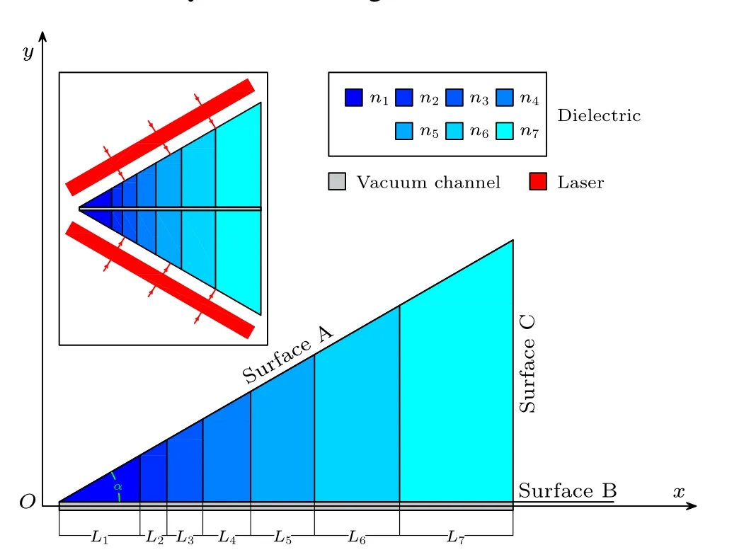
Fig.1.Schematic diagram of stacked acceleration structure.The accompanying diagram shows the simulation under axisymmetry.
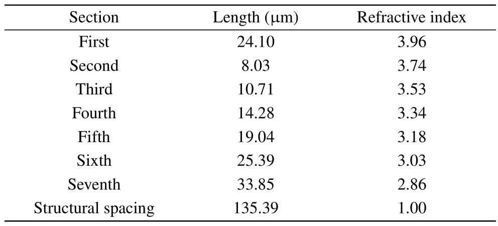
Table 1.Geometric structure simulation parameters.
The geometrical parameters of the simulated structures are listed in Table 1,and these designs fall within the range of what is currently achievable in laboratory setups.To capture the short time scale of the simulated physical process,[22-33]a far-infrared laser with a wavelength of 10.60µm was used.The laser was operated in a continuous plane wave mode(CW mode) with an electric field amplitude ofE0=6.0 GV·m-1.These chosen values result in a laser beam power density of approximately 6.6×10¹²W/cm2and an energy density of about 0.2 J/cm2on the prism surface.These parameter values align with those employed in previous studies.[29,32]
To achieve long-range synchronization, we propose the utilization of a linear laser pulse collimated by a cylindrical lens to drive a symmetric prism.The injected positrons have an energy of 50.00 keV and fall within the low energy nonrelativistic range(β ≪1), experiencing no initial energy dissipation.The charge of the positrons is approximately 9.36 fC.In the positron beam, the particles follow a Kapchinskij-Vladimirskij(KV)distribution,where they are uniformly distributed in phase space, and the distances between particles are approximately equal throughout the beam.[33]The initial normalized emissivity of the beam is 103pm·rad, and the initial maximum transverse distance from the beam center is 0.1µm,with a maximum divergence angle of around 23 mrad.The initial longitudinal length of the beam is approximately 3.54 fs, and the distance between the center of the positron beam and surface B on the prism surface is 0.5µm.These design parameters align with the parameters used in the present study.[32,34,35]
3.Simulation results and discussion
The energy spectrum of the accelerated positron beam stream at 742.51 fs, as shown in Fig.2, demonstrates the completion of the acceleration process.The peak energy in the spectrum is 436.15 keV, and the full width at half maximum (FWHM) of the energy dispersion is 1.33 keV, resulting in an energy dispersion of 0.33%.The total energy gain achieved during the acceleration process is 386.15 keV.The initial lack of energy dispersion also reduces the difficulty of regulating energy dispersion.With an acceleration distance of 135.39 µm, this corresponds to a peak average acceleration gradient of 2.85 GeV/m.The acceleration factor, defined as the ratio of the energy gain to the initial laser field strength(Eacc/E0),is 0.48.
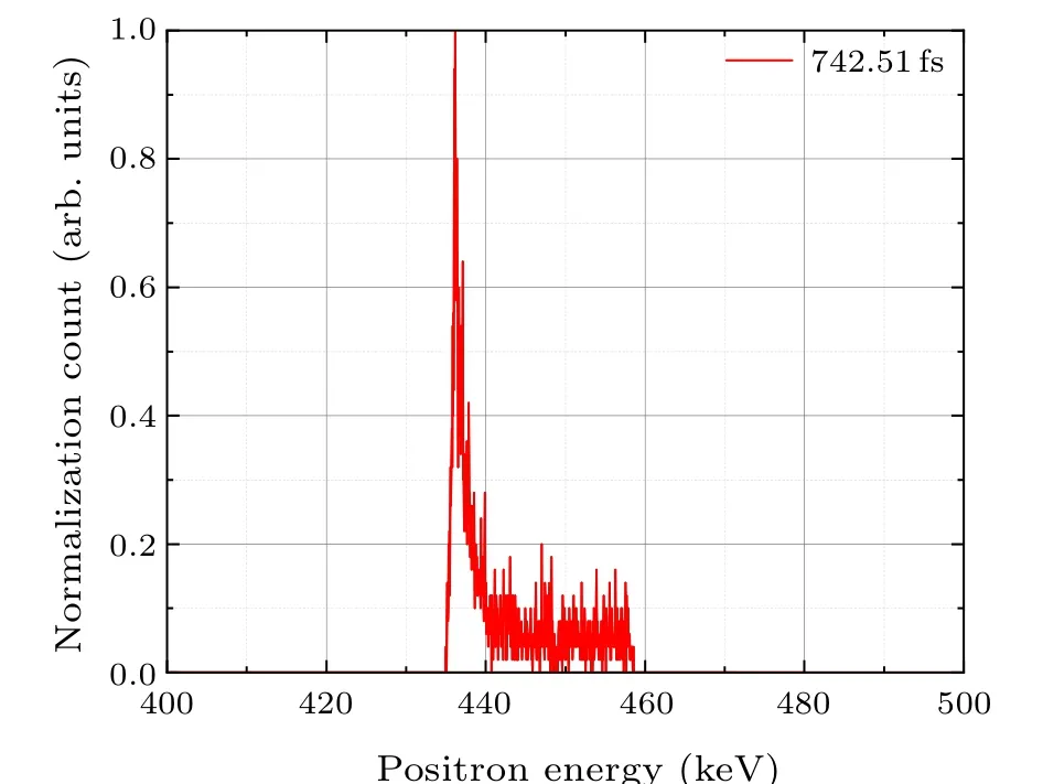
Fig.2.Positron beam energy spectrum at the end of acceleration,normalized to the peak.

Fig.3.Electric field Ex (magnitude normalized with respect to E0)as a function of time and space(x position).The vector of this field is in the lateral direction of the vacuum channel.The green line is the positron beam trajectory, and the sampling time step is 0.25T0. T0 is the optical cycle size of the laser,which is about 35.36 fs.The right color bar represents the normalized field strength,i.e.,Ex/E0.
In Fig.3,a world line diagram illustrates the full positron acceleration process.The green line represents the path of the positron beam as it advances through the accelerating electric field.The energy of the positrons monotonically increases along this path,with only slight jitter observed at the interlayer interface.This smooth increase indicates that the acceleration gradient remains stable and does not undergo significant changes at each stage of the process.The stacked acceleration structure maintains a continuous phase matching condition,allowing for the sustained acceleration of the positron beam.
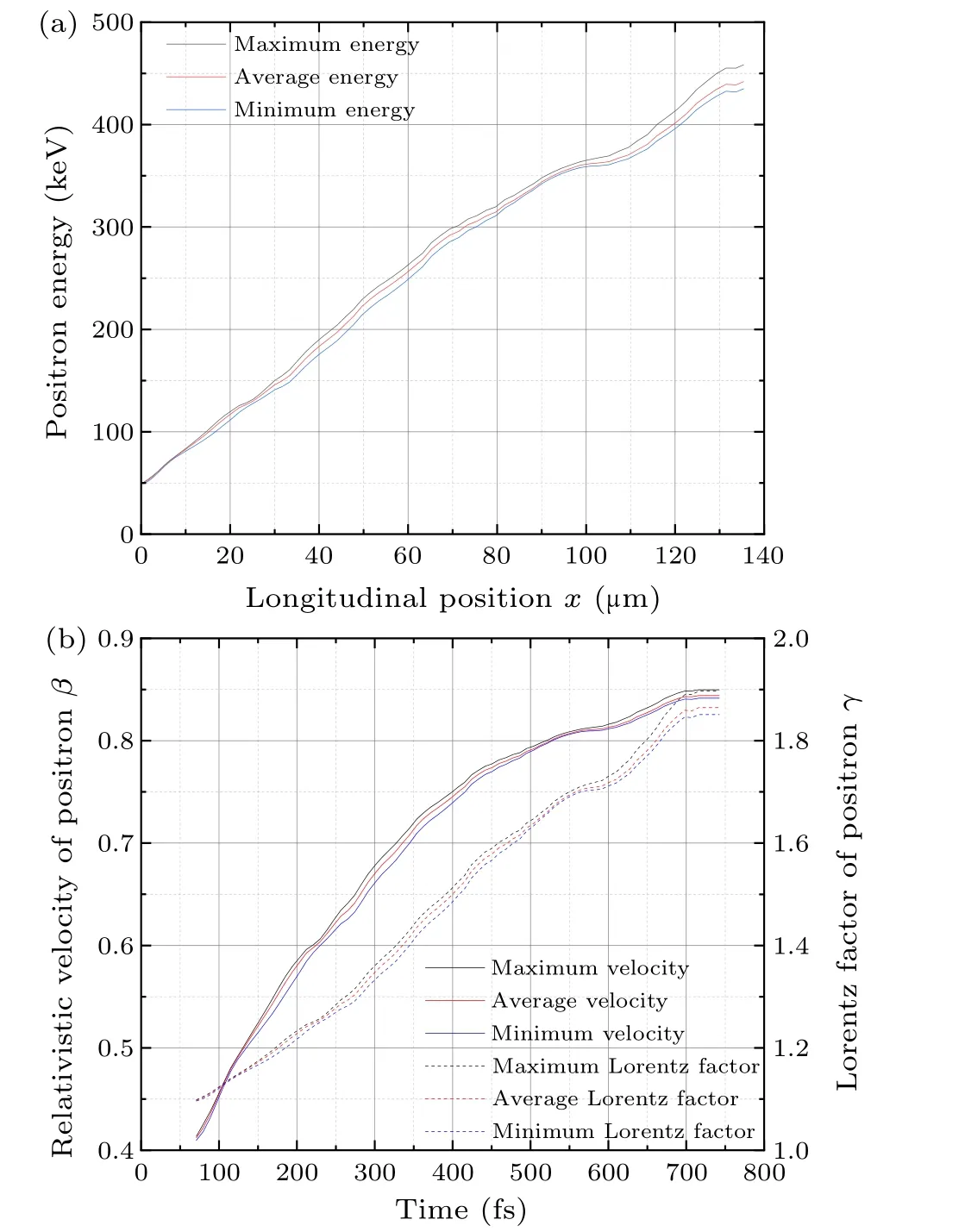
Fig.4.(a) Evolution of the maximum, average and minimum energy of positron beam with longitudinal position.(b)Evolution of the maximum, average and minimum velocity and Lorentz factor of positron beam with time.The sampling time step is 0.25T0.
The maximum, minimum, and average energies of the positron beam during the entire acceleration process were analyzed and are presented in Fig.4(a).It can be observed that these energy values are increasing.The straight line observed at the end of the beam is due to the completion of the acceleration process, however, the statistics are still being counted at this point.The slight decrease and rebound in energy before the straight line is attributable to the boundary effect of the acceleration channel.The maximum energy achieved by the positron beam is 458.51 keV.Similar to the above section,this corresponds to a maximum average acceleration gradient of 3.02 GeV/m.The minimum energy recorded is 434.97 keV, resulting in a minimum average acceleration gradient of 2.84 GeV/m.The average energy of the beam is measured at 442.00 keV,translating to an average acceleration gradient of 2.89 GeV/m.
Interestingly, it is observed that the difference between the maximum and minimum energies of the positron beam stream undergoes an“increasing-decreasing-increasing”process throughout the acceleration process.This phenomenon is consistent with previous studies on electron acceleration[32]and suggests that the stacked structure possesses an energetic self-compression property.
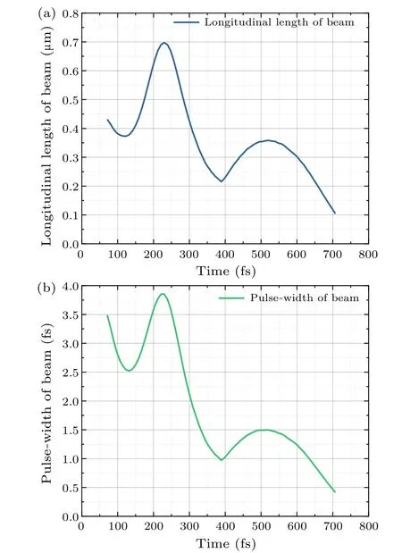
Fig.5.(a) Evolution of the longitudinal length of positron beam with time.(b) Evolution of the pulse-width of positron beam with time.In order to present the results better,only some points have been selected and the actual time step is 0.25T0.
Similarly,the maximum,minimum,and average longitudinal velocities and Lorentz factor of the positron beam stream throughout the acceleration process were analyzed,and the results are shown in Fig.4(b).The positron velocity follows a similar trend to the energy, steadily increasing.However, the rate of increase in velocity is slowed down by relativistic effects.Throughout the acceleration process, both the positron energy and velocity display minimal dispersions,which corresponds to the extremely low energy dispersion observed at the end of the process.inhomogeneous field distribution in the accelerating vacuum channel,as reported in the literature.[29-32]When the diffusion of the positron beam current becomes significant,the positive phase(Ex ≥0)of the decelerating electric field before and after the beam suppresses it and introduces negative feedback,leading to the alternating compression of the beam current.The specific process is shown in Figs.6(a)-6(f).Among them,Figs.6(a) and 6(b) show the main process during the simulation in this study, where the positron at the back end feels high electric field strength and high energy gain; the positron at the front end feels low electric field strength and small energy gain;and the positron at the center is in between.Therefore,inside the positron beam,the backward positron has been forward to catch up with the forward positron, realizing the compression of the positron beam.As may occur in some cases[Fig.6(c)],the front positron is decelerated and the back positron is accelerated,and the compression effect of the electric field on the beam current is more intense.Figures 6(d)-6(f) show the decelerated state, which is not involved in this simulation,and similar to the above analysis.It can be judged that Fig.6(d)shows a compression process and Figs.6(e)and 6(f)show diffusion processes.In addition,the above situation is based on the positron beam flow inside the nondispersive or low energy dispersion, corresponding to other particles or complex energy distribution situation needs to be specifically analyzed.
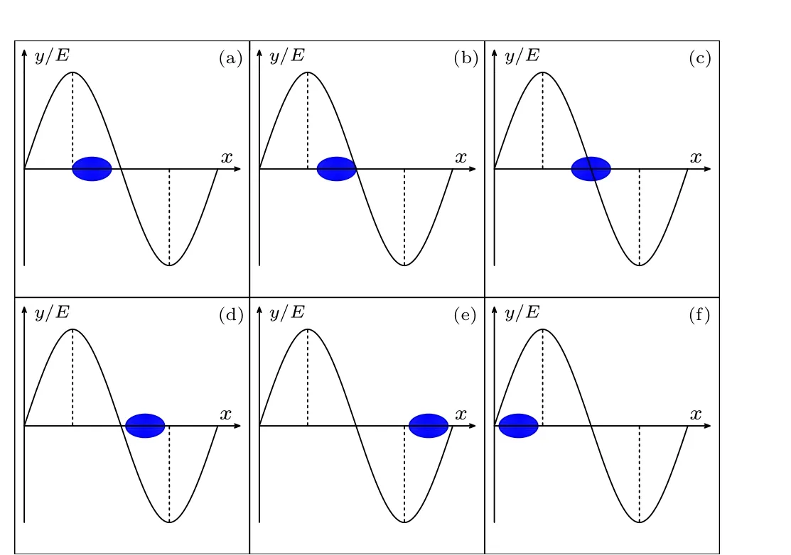
Fig.6.The position of the positron relative to the accelerating electric field during its motion.The blue ellipse indicates the positron beam and the black curve indicates the longitudinal electric field distribution.[(a),(b)]The back end of the beam is in a high acceleration gradient and the front end is in an acceleration low gradient;(c)the back end of the beam is in an acceleration state and the front end is in a deceleration state;(d)the back end of the beam is in a low deceleration gradient and the front end is in a high deceleration gradient;(e)the back end of the beam is in a high deceleration gradient and the front end is in a low deceleration gradient;(f)the back end of the beam is in a low acceleration gradient and the front end is in a high acceleration gradient.
Figures 5(a)and 5(b)illustrate the variations in the beam length and pulse width of the positron beam during the acceleration process.It is observed that both the beam length and pulse width undergo alternating“decrease-increase-decrease”compression with acceleration time, exhibiting a characteristic similar to stacked electron acceleration.[32]The stretching and spreading of the positron beam can be attributed to the
Additionally,the increasing velocity of the positron beam contributes to a relatively higher pulse width at the beginning of acceleration and a comparatively lower pulse width at the end of the acceleration stage.The initial beam length of the positron beam is measured at 0.43 µm, which is compressed to 0.10 µm after acceleration, corresponding to a compression rate of 23.26%.Similarly, the initial pulse width of the positron beam is 3.50 fs, and after acceleration, it reaches 411.00 as (or 0.41 fs), corresponding to a compression rate of 11.71%.As a result,the positron beam attains a remarkably short pulse width of only 411.00 as, making it highly valuable for various applications such as attosecond pulses,ultrafast diffraction,and other potential applications in the future.
4.Conclusion and perspectives
In summary, we propose a feasible scheme for efficient acceleration of low-energy positron beams using a stacked positron acceleration structure based on the inverse Cherenkov effect.This structure allows for high-gradient and high-energy gain acceleration of the positron beam.Furthermore,it enables high-quality acceleration with features such as ultra-fast pulse widths and low energy dispersion.One of the key advantages of the stacked positron acceleration structure is its flexibility in configuration.The energy adjustment of the output positron beam can be easily achieved by adjusting the number of stack layers.This flexibility opens up possibilities for various applications and makes the stacked positron accelerators promising for future use in chip-scale positron accelerators.Overall, this work presents a promising approach for efficient and high-quality acceleration of positron beams,offering potential benefits for a wide range of applications in the field of particle accelerators.
Acknowledgments
The authors thank Dr.Wei Li at the University of Science and Technology of China, Dr.Qiangyou He at the Peking University, and Dr.Lai Wei at Laser Fusion Research Center,CAEP,for the insightful discussion.This project was supported by the National Natural Science Foundation of China(Grant No.11975214).
杂志排行
Chinese Physics B的其它文章
- A multilayer network diffusion-based model for reviewer recommendation
- Speed limit effect during lane change in a two-lane lattice model under V2X environment
- Dynamics of information diffusion and disease transmission in time-varying multiplex networks with asymmetric activity levels
- Modeling the performance of perovskite solar cells with inserting porous insulating alumina nanoplates
- Logical stochastic resonance in a cross-bifurcation non-smooth system
- Experimental investigation of omnidirectional multiphysics bilayer invisibility cloak with anisotropic geometry
