Limit load and failure mechanisms of a vertical Hoek-Brown rock slope
2024-03-25JimShiauWarayutDokueaSuraparKeawsawasvongPitthayaJamsawang
Jim Shiau,Warayut Dokuea,Surapar Keawsawasvong,Pitthaya Jamsawang
a School of Engineering, University of Southern Queensland, Toowoomba, 4350, QLD, Australia
b Department of Civil Engineering, Faculty of Engineering, King Mongkut’s University of Technology Thonburi, Bangkok, Thailand
c Research Unit in Sciences and Innovative Technologies for Civil Engineering Infrastructures, Department of Civil Engineering, Thammasat School of Engineering,Thammasat University, Pathumthani,12120, Thailand
d Soil Engineering Research Center, Department of Civil Engineering, King Mongkut’s University of Technology North Bangkok, Bangkok,10800, Thailand
Keywords: Bearing capacity Rock slope Vertical slope Finite element limit analysis Hoek-Brown yield criterion
ABSTRACT The problem considered in this short note is the limit load determination of a vertical rock slope.The classical limit theorem is employed with the use of adaptive finite elements and nonlinear programming to determine upper and lower bound limit loads of a Hoek-Brown vertical rock slope.The objective function of the mathematical programming problem is such as to optimize a boundary load,which is known as the limit load,resembling the ultimate bearing capacity of a strip footing.While focusing on the vertical slope,parametric studies are carried out for several dimensionless ratios such as the dimensionless footing distance ratio,the dimensionless height ratio,and the dimensionless rock strength ratio.A comprehensive set of design charts is presented,and failure envelopes shown with the results explained in terms of three identified failure mechanisms,i.e.the face,the toe,and the Prandtl-type failures.These novel results can be used with great confidence in design practice,in particularly noting that the current industry-based design procedures for the presented problem are rarely found.
1.The problem
Hoek and Brown (1980) developed a failure criterion that is based on empirical approach for rock masses.It employed a series of triaxial test results of intact and jointed rocks.The impact of heavily fragmented rocks was further considered in the wellknown 2002 version of the Hoek-Brown (HB) rock material model(Hoek et al.,2022).It can be used to describe mathematically for the principal stresses(σ1and σ3),as shown in Eqs.(1)-(4).
whereGSIrepresents the geological strength index,miis the parameter for yielding,σciis the uniaxial strength of the intact rock mass,andDdenotes the disturbance factor.The HB yield criterion has been recently formulated into the advanced finite element limit analysis (FELA) package,i.e.Optum G2 (Optum CE,2021),and it is employed as tool for the current study.
Fig.1 shows the statement of the problem of a plane strain strip footing on a vertical HB rock slope.The slope has a vertical heightH.The rigid strip footing has a widthBand the distance from the edge of the slope to the edge of the footing isL.It follows that the proposed study has seven input variables,i.e.H,B,L,σci,GSI,mi,and the rock unit weight γ.Note thatDis assumed to be zero for undisturbed in situ rock masses.The footing is assumed to be very rigid so that the strength of the footing is large enough and would not fail before the underlying rock.The surface roughness of the footing is fully rough since we assumed that the underlying rock is fully connected to the footing.The theory of FELA is quite different from that of the displacement-based finite element method(FEM),as the former is a direct method for the perfectly plastic soil or rock model,and the elastic modulus plays no role in the computation.Therefore,the solution and output are only for stability prediction,but not displacement.
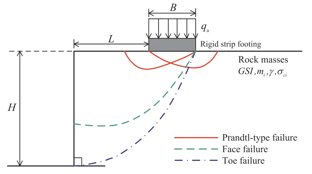
Fig.1.Problem definition.
To reduce these input parameters,dimensionless parameters were used throughout this paper.Consequently,for the output of bearing capacityqu,it is normalised with respect to γBand the relationship between the bearing capacity factorN=qu/(γB)and all five dimensionless input parameters can be stated as follows:
whereL/Bis the dimensionless footing distance,H/Bis the dimensionless height of a vertical cut slope,and σci/(γB) is the dimensionless strength ratio.The selected ranges of the HB strength parameters would cover most practical ranges in design practice since we follow the suggested ranges ofGSIandmifrom Hoek et al.(2022).Note that the bearing capacity of a footing on a vertical rock slope is largely affected by its developed failure mechanism.In generally,there are three possible failure mechanisms for the problem,i.e.the toe failure,the face failure,and the Prandtl-type failure,as illustrated in Fig.1.
Like most other numerical techniques,a finite element mesh is needed for the FELA analysis.Fig.2 shows a typical adaptive FELA mesh for the problem.The domain needs to have sufficient size to ensure that the overall velocity field is contained within the domain.Note that the left-handed,the right-handed,and the bottom boundaries have a distance of 2B,4Band 2B,respectively so that there is no intersection of the plastic zone at these boundaries.On the contrast,no boundary constraints are placed at the other surfaces,which are free to displace in all directions.The widthBof the footing is the boundary pressure to be optimized using the proposed FELA technique.It is interesting to note that,from the final adaptive mesh presented in Fig.2,the technique allows one to visually observing the locations of plastic zones and velocity discontinuities.All numerical simulations in this paper employed 5000 to 10,000 elements as the initial and the targeted number of elements with five adaptive iterations.This has been extensively tested and the accuracy of the results can be achieved with this proposed number of elements.
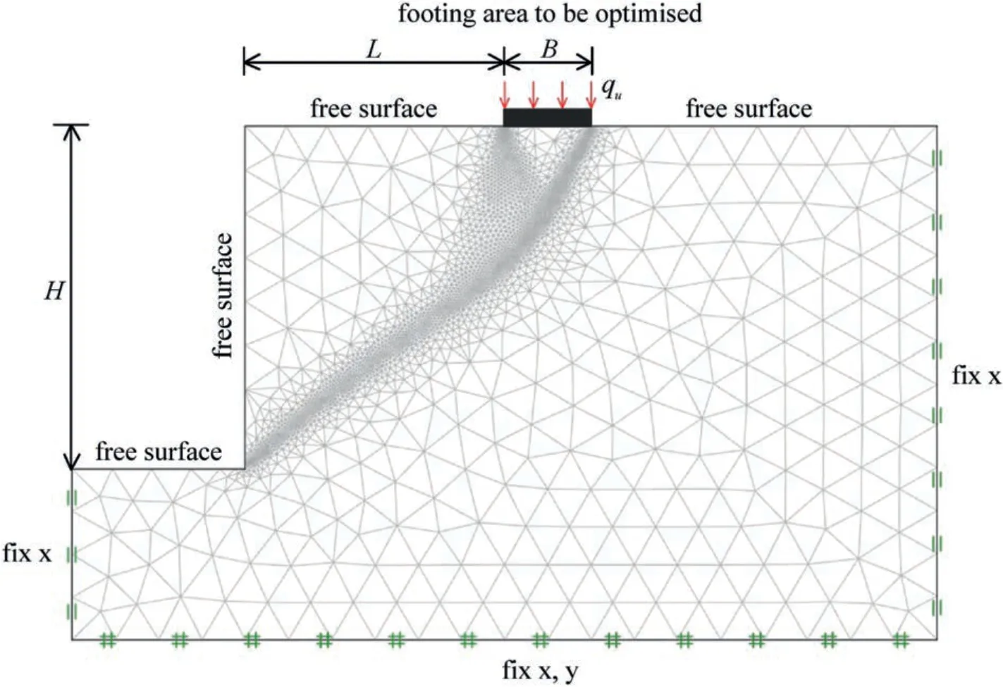
Fig.2.A typical adaptive FELA mesh used in the study (L/B=3, H/B=4,σci/(γB)=100, mi=2, GSI=50).
Since both UB and LB solutions can bracket the true solutions to within a few percentages,it is imperative that results produced by other numerical methods in the future should be compared with our rigorous solutions for validation.Interestingly,it is “theoretically” unnecessary to compare the current results with other published solutions,if any available.The FELA technique has been recently applied to several other geotechnical applications(Ukritchon and Keawsawasvong,2018;Keawsawasvong and Ukritchon,2019;Shiau and Al-Asadi,2021;Keawsawasvong and Shiau,2022a,b;Lai et al.,2022,2023;Shiau et al.,2023).Due to the space limit,more detailed discussions can also be found in Sloan (2013) and Krabbenhoft and Lyamin (2015).
2.Previous study and motivation to the research
Assessing the stability of footings located near slopes is not uncommon for geotechnical engineers in their daily design routine.Several researchers have attempted to determine the bearing capacity solutions of soil slope by employing various numerical and analytical techniques such as limit equilibrium method (Azzouz and Baligh,1983),slip-line method (Graham et al.,1988),finite element analysis (Georgiadis,2010a;Griffiths and Martin,2020),discontinuity layout optimization approach (Leshchinsky,2015),upper bound limit analysis (Georgiadis,2010b),lower bound limit analysis (Bhattacharya and Dutta,2020),and FELA (Shiau et al.,2004,2006,2011).It was noted that very few works were linked to the study of footings on vertical rock slopes.
The yield criterion developed by Hoek and Brown (1980) and later upgraded by Hoek et al.(2022) has been widely used to compute the limit load of vertically loaded foundations on level ground with rock masses (e.g.Serrano and Olalla,1994;Yang and Yin,2005;Keawsawasvong et al.,2022).Nevertheless,research on the effect of rock slopes on the bearing capacity solutions is quite limited(Zhou et al.,2018,2019).In this paper,the influences of rock characteristics as well as several other geometrical parameters on footing bearing capacity of vertical slopes are investigated by employing the FELA.Furthermore,the associated failure mechanisms are identified and grouped into three categories,i.e.the face,the toe,and the Prandtl-type failures.Finally,a set of useful design tables and charts are presented for practical uses.
3.Results and discussion
Fig.3 presents the variation of bearing capacity factorN(average of UB and LB) withL/Bfor the different values ofH/B,σci/(γB),miandGSI.In general,an increase inL/Byields a nonlinear increase inN.When the footing is located away from the vertical slope,the load transferring area becomes larger (potential failure zone),resulting in greater values of the bearing capacity factorN.Noting thatNbecomes a constant after a certainL/Bvalue,indicating a typical Prandtl-type ground failure mechanism.In Fig.3a,the larger the slope height ratio (H/B),the smaller theN.It follows that,in Fig.3b-d,the greater the values of σci/(γB),miandGSI,the less theN.No“face failure”is observed in Fig.3 since the height of vertical slope is considered as small (H/B=2).It was therefore decided to present Fig.4 using different parameters,in which face failure may be demonstrated.Interestingly,it is found that “face failure” only occurs at small values ofL/Band large values ofH/B(see the green dashed lines).More discussions on the type of potential failure mechanisms are discussed in a later section.
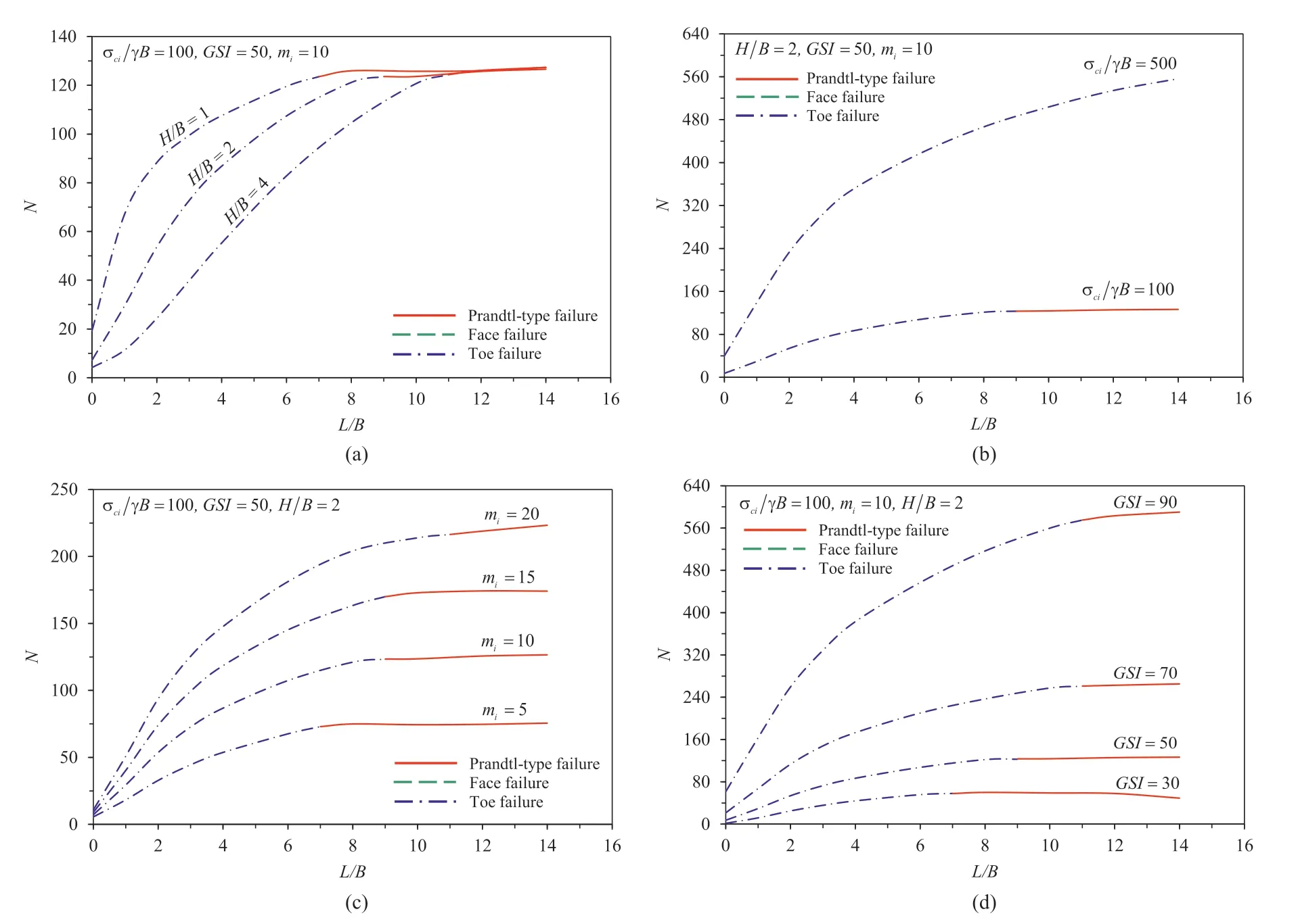
Fig.3.Variations of N with L/B for different values of (a) H/B,(b) σci/(γB),(c) mi,and (d) GSI.
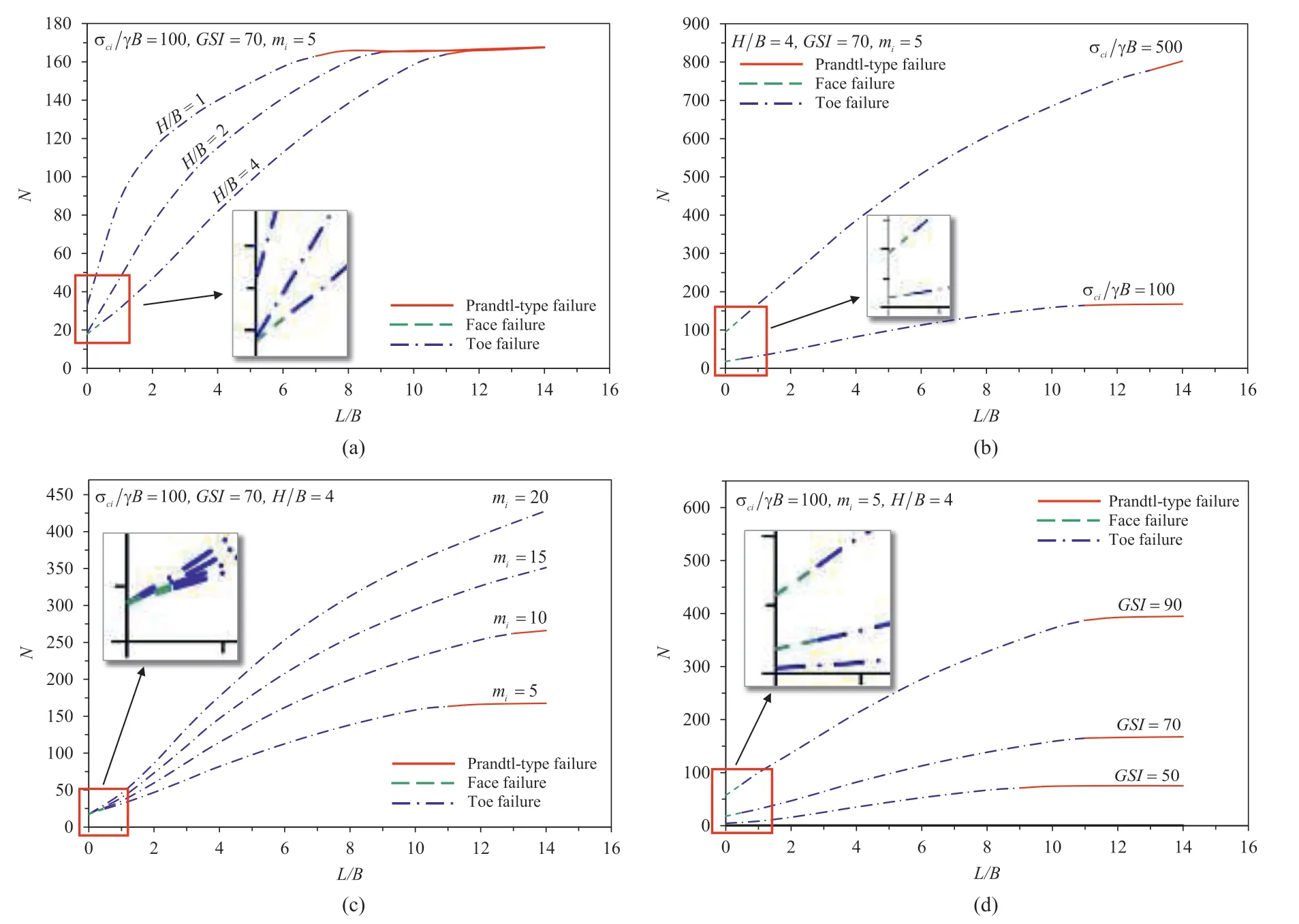
Fig.4.Effect of L/B on N by considering different values of (a) H/B,(b) σci/(γB),(c) mi,and (d) GSI.
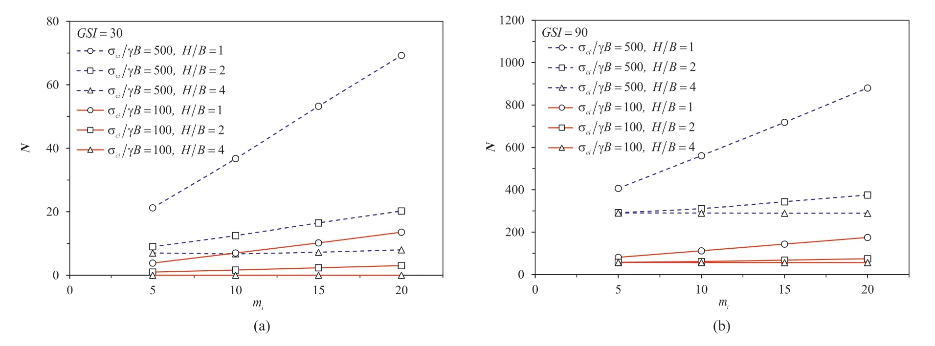
Fig.5.Variations of N with mi for different values of H/B and σci/(γB): (a) GSI=30 and (b) GSI=90.
The effects ofmiandGSIon the bearing capacity factorNare shown in Figs.5 and 6,respectively.Since the parametermiis a representative of the mineralogy,composition,and grain size of the intact rock (Hoek et al.,2022),an increase inmiresults in a linear increase inN.The greater the σci/(γB),the larger theN.The exponential relationship betweenGSIandNis presented in Fig.6.An increase inGSIyields an increase inNnonlinearly.Indeed,this nonlinear increasing curve is a result of the function in the HB model(see the exponential equation in Eqs.(2)-(4)).Interestingly,a greaterGSIvalue represents a near undisturbed rock mass,and therefore it would yield a greaterNvalue,as shown in Fig.6.
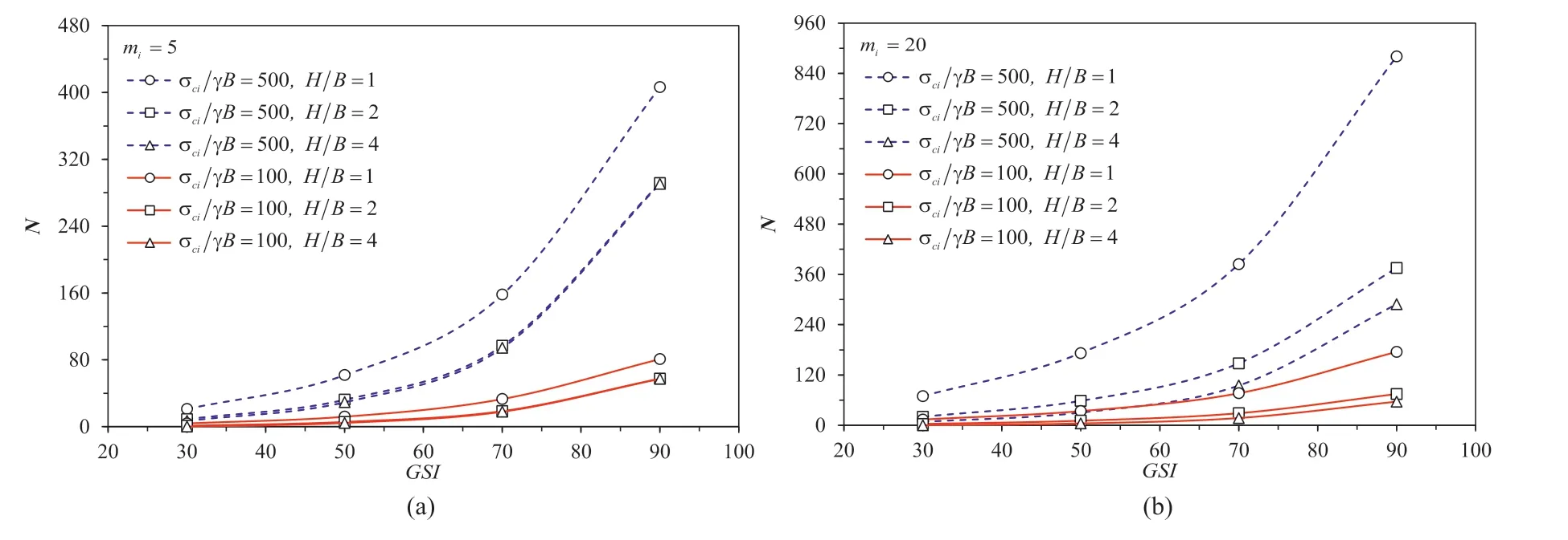
Fig.6.Variations of N with GSI for different values of H/B and σci/(γB): (a) mi=5 and (b) mi=20.
Several examples of potential failure mechanisms from the studies are presented in Fig.7.ForH/B=1 and 2 in Fig.7a and b,respectively,only two possible failure patterns are found in all values ofL/B(i.e.the toe and the Prandtl-type).The Prandtl-type failure occurs atL/B=8 and 10,respectively,forH/B=1 and 2.All others are for the toe failures.As the slope height ratioH/Bincreases(see for exampleH/B=4 in Fig.7c),a third possible failure surface is found at small values ofL/B,i.e.the face failure as shown in green colour.On the other note,the Prandtl-type failure occurs atL/B=12 (see Fig.7c,H/B=4).
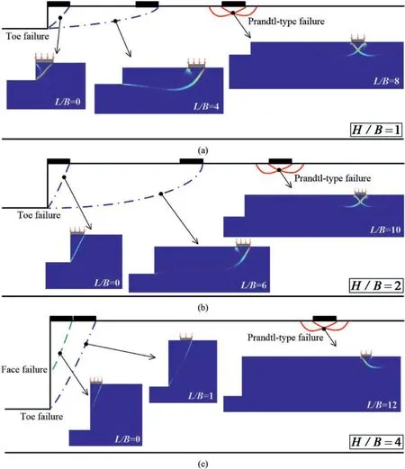
Fig.7.Potential failure mechanisms for various L/B and H/B (mi=5, GSI=70,σci/(γB)=100): (a) H/B=1,(b) H/B=2,and (b) H/B=4.
A design chart is therefore developed to identify the various failure patterns of a vertical slope.This is shown in Fig.8 for practical uses.In this chart,one can quickly determine a failure type by knowing the values ofH/BandL/B(see Zones I-III in the figure).It is to be noted that Zone III(face failure)can only be identified for small values ofL/Band large values ofH/B,whilst in contrast,Zone I(Prandtl-type) can be found at large values ofL/B.Zone II (i.e.toe failure)occurs in between Zones I and III,and by a larger proportion of the design map,it is for moderate values ofL/BandH/B.
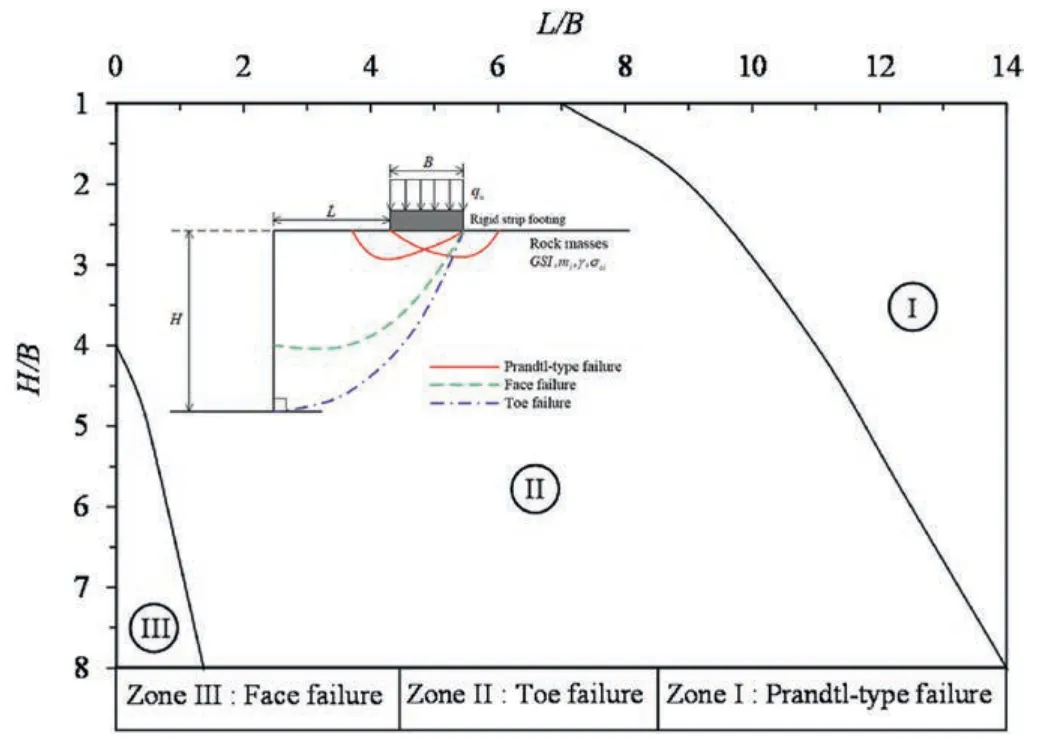
Fig.8.Various types of failure mechanisms (mi=5, GSI=70,σci/(γB)=100).
4.Example
For a vertical rock slope with a strip footing sitting on the surface with a distance ofL=4 m from a slope cut,it has a height ofH=2 m.The footing has a width ofB=1 m,and the rock has aGSI=70,mi=5,σci=2500 kPa,and γ=25 kN/m3.The bearing capacity (qu) of the footing is determined as follows:
(1) CalculateH/B=2/1=2,L/B=4/1=4,and σci/(γB)=2500/(25 ×1)=100.
(2) The bearing capacity factorNcan be obtained using Fig.4a,whereN=115.
(3) The bearing capacity (qu)is calculated as=115 × 25 ×1=2875 kPa.
5.Conclusions
A vertical rock slope has been investigated with respect to its stability under a strip footing using the HB failure criteria and the advance FELA of upper and lower bounds with adaptive meshing scheme.In this short technical note,both UB and LB solutions were confidently obtained within 3% accuracy,and they can be used to compare with new solutions from future research work.The current study has also successfully identified three distinct failure mechanisms for the problem,i.e.the toe,the face,and the Prandtltype.Practical design tables and charts for determining the limit load and identifying a corresponding failure type are presented.Finally,an application example was given to facilitate the determination of the ultimate capacity as well as the type of failure pattern of a given vertical rock slope.In view of the current lacking industry-based stability design procedures for a vertical rock slope,this novel short letter is of practical importance in assisting engineers in their daily design routine.A final note on the future work recommendation is an extension for studying various rock slope angles and the use of machine learning approach to provide a predictive model.Besides,the current work can be expanded to a full 3D analysis using rectangular or circular footings,as the current solutions are limited to the cases of planar footings on homogeneous rock slopes.
Declaration of competing interest
The authors declare that they have no known competing financial interests or personal relationships that could have appeared to influence the work reported in this paper.
Acknowledgments
This research was funded by National Science,Research and Innovation Fund (NSRF),and King Mongkut’s University of Technology North Bangkok with Contract No.KMUTNB-FF-66-12.
杂志排行
Journal of Rock Mechanics and Geotechnical Engineering的其它文章
- Using deep neural networks coupled with principal component analysis for ore production forecasting at open-pit mines
- Sliding behaviors of the trapezoidal roof rock block under a lateral dynamic disturbance
- Real-time arrival picking of rock microfracture signals based on convolutional-recurrent neural network and its engineering application
- Failure characterization of fully grouted rock bolts under triaxial testing
- Nonlinear constitutive models of rock structural plane and their applications
- Mechanical behaviors of backfill-rock composites:Physical shear test and back-analysis
