A Fusion Localization Method Based on Target Measurement Error Feature Complementarity and Its Application
2024-03-18XinYangHongmingLiuXiaokeWangWenYuJingqiuLiuSipeiZhang
Xin Yang, Hongming Liu, Xiaoke Wang, Wen Yu, Jingqiu Liu, Sipei Zhang
Abstract: In the multi-radar networking system, aiming at the problem of locating long-distance targets synergistically with difficulty and low accuracy, a dual-station joint positioning method based on the target measurement error feature complementarity is proposed.For dual-station joint positioning, by constructing the target positioning error distribution model and using the complementarity of spatial measurement errors of the same long-distance target, the area with high probability of target existence can be obtained.Then, based on the target distance information, the midpoint of the intersection between the target positioning sphere and the positioning tangent plane can be solved to acquire the target’s optimal positioning result.The simulation demonstrates that this method greatly improves the positioning accuracy of target in azimuth direction.Compared with the traditional the dynamic weighted fusion (DWF) algorithm and the filter-based dynamic weighted fusion (FBDWF) algorithm, it not only effectively eliminates the influence of systematic error in the azimuth direction, but also has low computational complexity.Furthermore, for the application scenarios of multi-radar collaborative positioning and multi-sensor data compression filtering in centralized information fusion, it is recommended that using radar with higher ranging accuracy and the lengths of baseline between radars are 20-100 km.
Keywords: dual-station positioning; feature complementarity; information fusion; engineering applicability
1 Introduction
With the rapid development of military technology, the iteration of air defense equipment and increasingly complex battlefield environment,modern warfare has shifted from the single platform to the systematic confrontation.Traditional monostatic radar is not applicable for the contemporary warfare with increasing challenges and complex combat requirements [1].As the critical and important sensor, radar’s networking capability has drawn significant attention, and distributed radar networking for collaborative detection has become an inevitable trend [2].Multi-radar collaborative detection can effectively improve the combat effectiveness and survivability of radars.Moreover, it also fully utilizes the advantage of information and fire support of the systematic confrontation.By reducing the ambiguity of target information and the influence of sensor errors, after information fusion, the more accurate target status information can be obtained [3,4].
The collaborative detection of radar networking mainly includes three parts: spatiotemporal unity, localization, and filtering.Spatiotemporal unity includes coordinate transformation and time registration.The former means that converting the observations of target by multiple radars into the same observation coordinate system.And the latter is that the time when multiple radars observe the target must be consistent.Commonly used time registration methods are the least squares method and the interpolation and extrapolation method [5,6], which will not be further discussed here.
Due to the different number, working status and positioning principles of radars, multi-radar collaborative positioning is divided into multistation passive positioning, (T/R)nmulti-station positioning andT/R-RnorT-Rnmulti-base positioning [7-18].Further, multi-station passive positioning can be divided into two-step positioning methods and direct position determination(DPD) methods.In two-step positioning methods, after the target position parameters are estimated from signals intercepted.geometric positioning techniques, such as using multiple target positioning lines or positioning planes to intersect, are utilized to establish target positioning equations, which can be solved by exhaustive search [8,9], least squares estimation [10], pseudolinear method [11], Taylor expansion combined with gradient methods [13], etc.In contrast,DPD methods do not require target parameter estimation.It directly uses the correlation between target positioning parameter information contained in signals and signals to construct and solve target functions or cost functions, which are related to the target’s position [14-16].Compared to active positioning methods, the geometrical dilution of precision (GDOP) map of multistation passive positioning is unevenly distributed and the target positioning accuracy is low.
In Ref.[17], for multi-base positioning, theT/R-Rnactive and passive target positioning technology was discussed by adding multiple receiving stations, which mainly equivalent ton T/R-Rbistatic positioning.The target measurement parameters were grouped and formed into measurement subsets, and the positioning was performed by employing the simplified weighted least squares method or measurement subset optimization fusion algorithm.However, due to the insufficient utilization of redundant information between target positioning parameters and the lack of consideration for the spatial distribution characteristics of target positioning errors,when the angle measurement error increases,the target positioning accuracy will decrease significantly.Furthermore, if multiple receiving stations are replaced with multiple monostatic radars, the target position is determined by the intersection of multiple positioning spherical surfaces of the same target.However, it requires at least three monostatic radars with appropriate deployment.Similarly, since only the target distance information is utilized, the influence of angle measurement errors and the spatial distribution characteristics of target positioning errors are not be considered, the positioning accuracy for long-distance targets is poor.On the other hand, in Ref.[18], only two monostatic radars are used to locate long-distance targets cooperatively,which has considered the azimuth and distance information and by taking the advantage of the higher ranging accuracy, combining the cosine theorem, a dual radars collaborative positioning algorithm is proposed.Compared to single radar,it has the higher precision for long-distance targets.Although the article only analyzed the target positioning in two-dimensional plane rather than in three-dimensional space, the idea that utilizing the high-precision target distance information and the geometric relationship between the target and radars for improving the long-distance target positioning accuracy is worth learning.
The ultimate goal of multi-radar collaborative positioning is to achieve accurate target tracking, and the track fusion is one of the most important application areas for multi-sensor information fusion [19-22].According to the fusion structure, current fusion estimation algorithms are roughly divided into three categories:centralized, distributed and hybrid.Without any loss of information, the centralized fusion can utilize the raw measurement data of all sensors and acquire the optimal fusion result, which is also the main focus of this article.Furthermore, for the scenario that the measurement noises of different sensors are uncorrelated at the same time,common centralized fusion algorithms include parallel filtering, sequential filtering, and data compression filtering [23].
Based on the extension of the Kalman filter(KF) algorithm, the centralized fusion algorithms that using parallel filtering and sequential filtering structures mainly process target track data by predicting and weighted fusion,while the data compression filtering method is based on the weighted least squares estimation to complete multi-sensor data fusion [24-26].Refs.[27] and [28] have shown that the centralized fusion method that using sequential filtering and data compression filtering have the same estimation accuracy as the parallel filtering structure.In addition, centralized fusion algorithms considering the correlation between measurement noise of different sensors can refer to Refs.[29] to [30].Of course, many nonlinear filtering algorithms have been derived for considering different target motion models and nonlinear systems,such as the extended Kalman filter (EKF), unscented Kalman filter (UKF) and particle filter (PF)[31-33].
Analyzing the existing positioning algorithms and centralized fusion algorithms, there are two shortcomings.First of all, many related works are mainly on multi-station passive positioning andT/R-RnorT-Rnmulti-base positioning.But there are few studies on (T/R)nmultistation collaborative positioning.Moreover, in above algorithms, since without considering the geometric relationship between the target and radars, the spatial characteristics of the target positioning error distribution and the complementary between multiple measurement results,when the information is missing or distorted, it is difficult to obtain the target’s optimal positioning result.Secondly, for traditional weighted fusion algorithm, DWF algorithm and FBDWF algorithm, both filtering and weighting are linear methods, which can’t acquire the best positioning results [34-37].Therefore, the fusion result for locating long-distance targets is out of the uncertainty area of multi-sensor measurement,which means that the target positioning error is large.
Aiming at the problem of locating long-distance targets synergistically with difficulty and low accuracy, which has not been considered in existing literatures.This article pays attention to engineering applicability for long-distance target positioning in multi-radar networking systems.By analyzing the influence of radar measurement error for targets, the target positioning error distribution model is constructed.Then, for two or more monostatic radars collaborative positioning, by utilizing the complementarity of spatial measurement errors of the same long-distance target, the area with high probability of target existence can be obtained.Finally, based on the high-precision target distance information and the geometric relationship between the target and radars, the midpoint of the intersection between the target positioning sphere and the target positioning tangent plane can be solved to acquire the target’s optimal positioning result.So, a dual-station fusion localization method based on the target measurement error feature complementarity is proposed.
2 Target Positioning Error Distribution Model
The measurement and estimation of target parameters are the fundamental task of radar.However, due to differences in the working mechanism of the radar and the signal waveform parameters used, the obtainable target parameters and spatial error distribution area will also be different.The focus here is on tracking measurement radar.It is noted that the article focuses on tracking measurement radar.
Firstly, focusing on the angle direction, the main sources of error are thermal noise in the target channel, target scintillation errors, and errors caused by encoder quantization or other factors.Further, the angle error caused by thermal noise is generally considered as a Gaussian random distribution with the root mean square(RMS) given by the following equation.
whereθ0.5represents the radar half beam width ,SNR is signal-to-noise ratio, andkis a constant.Similarly, other angle error components can be analyzed.Such as the angle quantization error is uniformly distributed and its RMS value is represented as
whereQis the angle quantization factor.
So, multiple angle error components are superimposed together to form the distribution of Gaussian noise with non-zero mean.Numerically,the angle error does not change with target distance.But when detecting targets in Cartesian Space, even if the angle error remains unchanged,the error in angle direction will increase significantly as the target detection distance becomes farther.
Differently, distance error components include thermal noise, target scintillation error,data quantization error, calibration error, error of uncertainties caused by signal waveform, timing or transmission pulse jitter, etc.Similarly, distance errors caused by thermal noise are also generally assumed to follow the distribution of Gaussian noise with non-zero mean, and the root mean square error (RMSE) can be expressed as
wherecis the speed of light,τeis the pulse width after pulse compression, andnRis the number of smooth pulses.
In the same way, other distance error components can be analyzed.Such as the RMSE of the distance clock can be represented as represented as
wherefcis the clock base frequency.Multiple distance error components are combined to behave as a distribution of Gaussian noise with a nonzero mean.And it is worth noting that the distance error does not change with the increase of target distance and angle error.So, by using the higher precision sampling clock and quantization methods, even if the radar is responsible for the search mission, it can still obtain appropriate distance accuracy.
However, as the target detection distance increases, the error range caused by angle errors in azimuth direction and pitch direction will be much larger than the range of distance error.The distribution of target positioning error space shows a typical “watermelon peel” shape, which as shown in Fig.1.
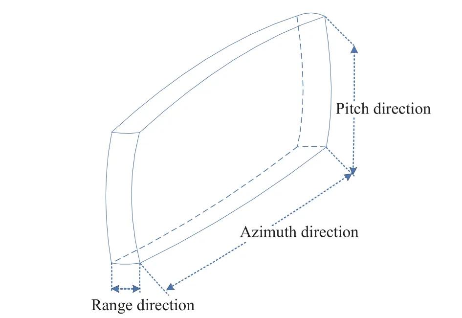
Fig.1 The range of target positioning error
When two or more radars observe the same target, through the intersection of multiple target positioning error space areas, proper deployment of radars can reduce the range of target positioning errors, which provides the potential to acquire the best target position result.
3 Methodology
3.1 The Principle of Positioning
The basic idea of multi-radar collaborative positioning in this article is that when two or more radars observe the same target, based on the proper deployment of radars, which can reduce the range of target positioning errors.Then through the intersection of multiple target positioning error space areas to obtain the high probability space area where the target exists.Finally, solving for the center of this area, which is the best positioning estimation result of the target.
The diagram of the dual-station positioning based on the complementary characteristic of target error space distribution is illustrated in Fig.2.
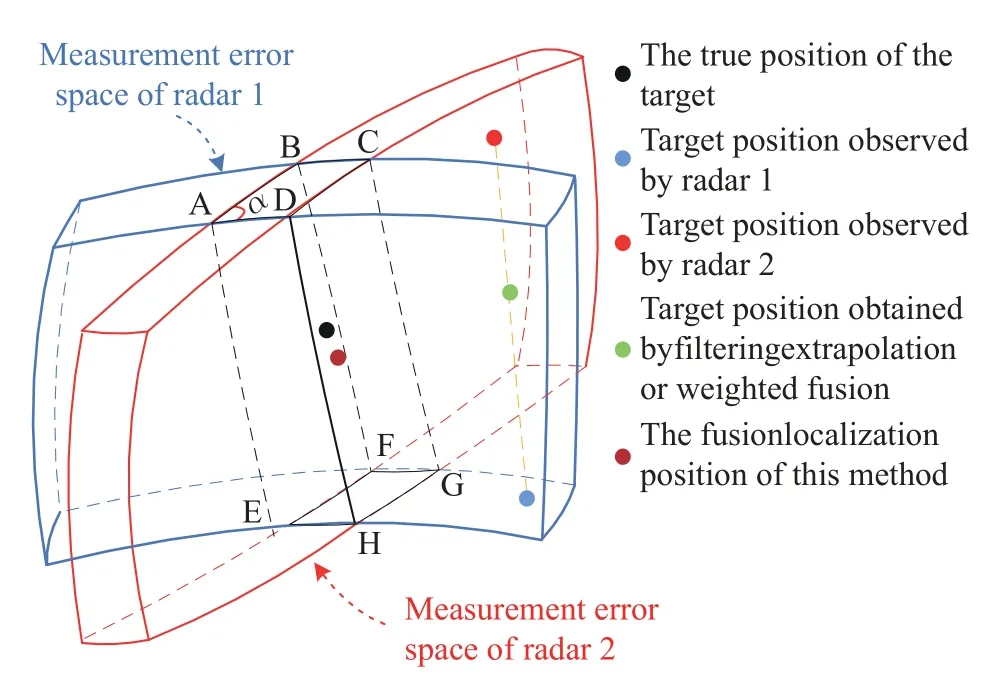
Fig.2 Schematic diagram of dual-station location
In order to cover all possible areas where the target may exist, in the distance and angle dimension, the one-sided error range of the radar should be maximized, which can be represented by taking the sum of 4 times random error and 1 times systematic error.
In Fig.2, the blue and red areas are the possible uncertainty areas that the target may exist and the error space ranges of target detected respectively by radar 1 and radar 2.So, by calculating the center of the intersecting space area ABCD-EFGH with high probability that the target exists, the best positioning estimation result of the target can be obtained.
From Fig.2, it can also be observed that through linear weighting methods such as filtering and least squares, in the spatial area of the target observed by two radars, both the extrapolation and weighted fusion positioning results exceed the areas where the target may exist.And for locating long-distance target, due to the ranging error is generally much smaller than the positioning error in azimuth and pitch direction, this feature is even more obvious.
Therefore, in the process of dual-station collaborative positioning for the long-distance target, high-precision target distance information can be more trusted and treat it as zero.Further,in the space, the uncertain area of target positioning can be approximated as a positioning slice.The midpoint on the intersection line of the two positioning slices will be the optimal fusion positioning estimation result of the target.
3.2 Algorithm Description
3.2.1 Spatiotemporal Unity
When each radar uploads the target track to the radar data fusion center, due to the existence of time delay error and the different observation coordinate systems and data rates of radars, it is necessary to complete the time registration and coordinate transformation of various target data from radars.
Time registration refers to the strict alignment in time domain for the track data of the same target.Here, we simply use the target velocity (Vx,Vy,Vz) obtained by the filter to extrapolate the target position at the desired moment.
Under the north-up-east (NUE) coordinate system with the fusion center as the origin, the coordinate of the radariis (Xi,Yi,Zi) andi=1,2.The result observed for the target m by the radar i at the previous moment is (X˜m,i,Y˜m,i,Z˜m,i).The time difference is Δt.So, the target position (Xmi,Ymi,Zmi) at the next moment can be extrapolated from the following formula.
Considering engineering applications and practical situations, the geodetic coordinate system is selected as the coordinate system to perform coordinate transformation.If the fusion center and station coordinates of two radars are known as (L0,B0,H0) and (Li,Bi,Hi).
In order to achieve coordinate unification of target track data, it is necessary to convert the coordinatethat the radariobservation targetmin the NUE coordinate system into the coordinate (Xmi,Ymi,Zmi) in the NUE coordinate system with the fusion center as the origin by using the following formulas
The matrixFlis given by
The matrixWlis given by
The variableNlis given by
The coordinate (Xmi,Ymi,Zmi) is the coordinate of the target in the geocentric rectangular coordinate system.And it is noted that the constantaand the constanteare the semi-major axis and the first eccentricity of the earth respectively.
Then,l=0,i.So, whenl=i, the variableNi,matrixFiand matrixWican be obtained.Whenl=0, the variableN0, matrixF0and matrixW0can be obtained.
3.2.2 Judgment of Intersectionality
Considering the complex spatial relationships between positioning slices, such as there are various scenarios ranging from perfect orthogonal complementarity to small-angle intersection or complete non-overlapping, which depend on relationship of the target and radar position.So, for multi-radar collaborative positioning of long-distance targets, the judgment of intersectionality between positioning slices is a necessary step.
IfRmiis the measurement distance of the radarito the targetm, then the positioning sphericalequationforthe targetmisξi=
Taking dual-station collaborative positioning as an example, for the same target and using the following formula, by judging whether two endpoints (x1,y1,z1) and (x2,y2,z2) on the boundary line of the target positioning slice of radar 2 are on the opposite side of the target positioning sphereξm1of the radar 1, it can indirectly determine the intersection relationship between target positioning slices of two radars.
If Eq.(8) is satisfied, the endpoint (x1,y1,z1)and the endpoint (x2,y2,z2) are on opposite side rather than the same side.Therefore, there is an intersection relationship between the positioning slice of two radars.
3.2.3 Solve for Intersecting Area
Based on the analysis in Section 3.1, the distance error can be considered as zero.So, for the radaritaking the sum of 4 times random error and 1 times systematic error to represent the maximum one-sided error range of the angle direction, which can be denotedσAiin azimuth direction andσEiin pitch direction.If(Rmi,Ami,Emi) is the polar coordinates of target observed by radari, the target positioning slice of radarican be obtained by using
The overlapping area of the target pos itioning slice of two radars is usually an arc segment.Taking the example of the arc segment that the positioning slice of radar 2 intersects with the positioning sphere of radar 1, two endpoints of the arc segment arePf1(x1,y1,z1) andPe1(x1,y1,z1).The solution process is as follows:
1) The vertex sorting of the radar 2 target positioning slice is recorded asp2j, andj=1,2,3,4.
2) Initializing the number of intersectionsCfe=0, the starting point and the ending point arePf1(0,0,0)Pe1(0,0,0) respectively.
3) Substituting each vertex into the equationξm1(x,y,z) to obtain the function valuesξp_2j(x,y,z).
4) Processing the first and last points of the line segment, which means that ifξp_21=ξp_24=0,letPf1=p21andPe1=p24, exit the search process.
5) Traversing the vertex from the first pointp21, for the pointp2j:
a.If there areξp_2j ξp_2(j+1)≤0 andCfe=0, calculating the intersection pointpnewbetween the current line segment and the sphere plane.Then letPf1=pnew,Cfe=1, continue the search process.But ifξp_2j=0, letPf1=pnew=p2jandCfe=1, continue the search process.
b.If there areξp_2j ξp_2(j+1)≤0 andCfe=1, calculating the intersection point between the current line segment and the sphere plane.Then, letPe1=pnewandCfe=2, exit the search process.However, ifξp_2j=0, letPe1=pnew=p2jandCfe=2, exit the search process.
3.2.4 Estimate Target’s Optimal Positioning Result
First of all, the intersection pointPf1(x1,y1,z1)andPe1(x1,y1,z1) between the target positioning slice of radar 1 and the target positioning sphere of radar 2.The midpoint of the line segment connecting the pointPf1andPe1can be used as the positioning result 1.In the same way, by using the method in section 3.2.3, the intersection pointPf2(x3,y3,z3) andPe2(x4,y4,z4)between the target positioning slice of radar 2 and the target positioning sphere of radar 1 can be solved.Then, the midpoint of the line segment connecting the pointPf2andPe2can be used as the positioning result 2.
For dual-station collaborative positioning, as shown below, the average of two positioning results will be the optimal positioning result.
In summary, based on the complementary characteristic of target measurement error, the flow chart of the fusion localization algorithm is shown in Fig.3.
3.3 Evaluate Algorithm Performance
It is evident that the proposed algorithm relies on the complementary feature of the target positioning error distribution space between radars,which means the smaller the area where the target positioning error space of multiple radars intersect, the better for the target positioning accuracy of multi-radar collaborative positioning.So, this feature can be used to evaluate algorithm performance.
As shown in Fig.4, taking dual-station collaborative positioning as an example, when the target is far away and the pitch angle of target detected by radars is relatively low, in horizontal plane, by observing from the perpendicular direction to the line of radar sight, the twodimensional uncertainty area of target exists can be approximated by the two-dimensional uncertainty area of target distribution in the azimuth and range direction.
αis the angle of target positioning error space of two radars.l1andl2are the length of the target positioning error space of two radars in the azimuth direction.Then, the overlapping area in Fig.4 is the quadrilateralABCD.
Further, the value ofl1,l2, |AB| and |AD| can be calculated according to the cosine theorem and the following formula
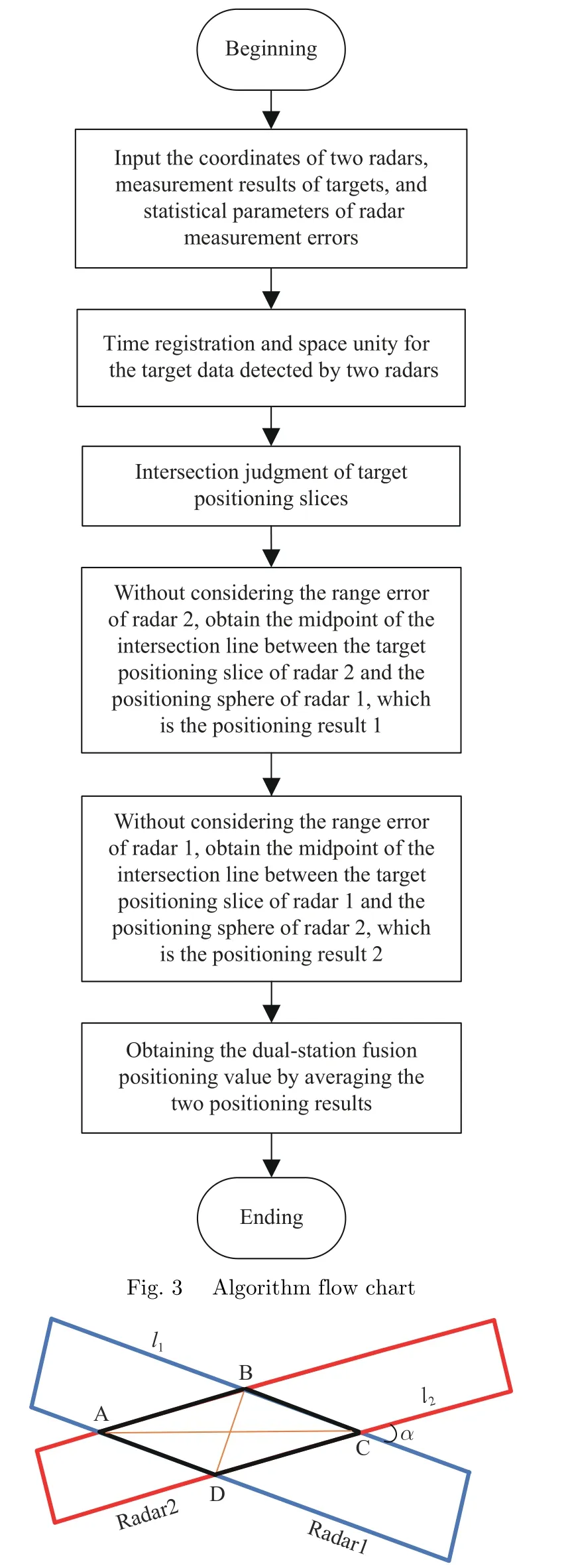
Fig.4 The two-dimensional uncertainty regions of target in azimuth and range directions
And it is known thatl1andl2are the maximum positioning error ranges of radar 1 and radar 2 in the azimuth direction.
So, the maximum positioning error Errormaxof the algorithm proposed in this article can be approximately calculated by
4 Verification of Simulation
In order to verify the effectiveness of the algorithm in this article, the DWF algorithm and the FBDWF algorithm will be simulated and compared with the algorithm.For the scenario of two radars collaborative positioning, in the NUE coordinate system with the fusion center as the origin, radar 1 is located at (-20 km, 0, 0) with system error(20 m, 0.2°, 0.2°)and random error of (30 m, 0.3°, 0.3°) in the distance, azimuth and pitch direction.But radar 2 is located at (20 km,0, 0) with system error (20m, 0.2°, 0.2°) and random error of (50 m, 0.5°, 0.5°) in the distance, azimuth and pitch direction.Then, the simulated target is located in the side view areas of two radars, within the azimuth range of -60°to 60°.
When the target flies at a constant altitude of 5 km and a distance range of 300 km to 250 km,as shown in Fig.5, in theX(represents the azimuth direction),Y(represents the pitch direction), andZdirection, the comparative results of the positioning error of two radars and the three algorithms are given respectively.And for two radars and the three algorithms, the Tab.1 shows the comparison results of the positioning RMSE.

Fig.5 Schematic diagram of target positioning error: (a)X direction; (b)Y direction; (c)Z direction
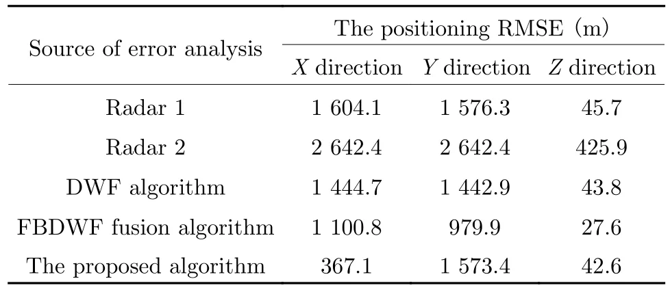
Tab.1 The comparison of the positioning RMSE
Obviously, as shown in Fig.5(a) and Tab.1,in theXdirection, the original positioning errors of radar 1 and radar 2 are the largest, and the positioning RMSE are 1 604.1 m and 2 642.4 m respectively.Compared with the positioning RMSE of the DWF algorithm and the FBDWF algorithm with system error inXdirection, which are 1 444.7 m and 1 100.8 m, the positioning RMSE of the algorithm proposed in this article is only 367.1 m.This means that it not only eliminates the influence of systematic error in the azimuth direction, but also has the best positioning effect and the smallest positioning error.
Similarly, as shown in Fig.5(b), Fig.5(c)and Tab.1, in theYandZdirection, the positioning effect of the algorithm proposed in this article is the worst, which is basically consistent with the best positioning effect of one of two radars.Compared with the DWF algorithm,since filtering can effectively eliminate the influence of noise and fluctuation error, the FBDWF algorithm has the best positioning effect in theYandZdirection.
In addition, in theXdirection, it is worth noting that the noise and fluctuation error have a greater impact on the algorithm proposed in this article compared to the FBDWF algorithm.In the future, some relevant filtering algorithms can be studied to eliminate the influence of noise and fluctuation error.Therefore, in azimuth direction,the accuracy of dual-station collaborative positioning can be further improved.
Through simulation and theoretical analysis,the effectiveness of the algorithm proposed in this article is verified.The simulation results also show that the algorithm greatly improves the positioning accuracy of the target in the azimuth direction.But the positioning accuracy in the pitch direction is not high, which is basically consistent with the best positioning effect of one of two radars.So, focusing on the positioning accuracy in theXdirection andXOZplane, the influencing factors of the algorithm can be analyzed,which mainly include the baseline length and the ranging accuracy of two radars.
In fact, because the system error in distance direction of radar is always much lower than random error of distance measurement and the maximum one-sided error range of the other radar in the angle dimension, and to ensure the error region can overlap, the one-sided error range of the radar in the angle dimension will be maximized to cover all measurement values as much as possible.Therefore, if there are systematic biases present in distance and angle direction, it has less impact on the algorithm.Further, when analyzing the impact of the baseline length and the ranging accuracy of two radars on the algorithm, the systematic biases in distance and angle direction does not need to be considered.
So, let the target fly close to two radars at a constant speed from 300 km away along the center vertical direction of the two radar baselines,and for two radars, by setting the random error of angle measurement to 0.5° and systematic biases to zero in distance and angle direction,when the ranging accuracy is 20 m and baseline lengths of two radars are 20 km, 40 km, 60 km,80 km and 100 km respectively, after the target distance is equally divided into segments of 25 km,the comparison of the positioning RMSE inXdirection are given in the Tab.2.Then, similarly,change the ranging accuracy of two radars to 100 m,the simulation comparison results of the positioning RMSE inXdirection are shown in Tab.3.
According to Tab.2 and Tab.3, three conclusions can be obtained.The first one is that when the baseline length of two radars is fixed,the greater the ranging accuracy of two radars is,the greater the positioning RMSE will be.This is because when performing dual-station positioning, the algorithm is highly dependent on the ranging accuracy of target.The second conclusion is that the farther the target distance or is or the shorter the baseline length of two radars is, the worse the algorithm performance will be.This is because the angle measurement error spreads in azimuth and pitch direction, which will lead the farther the target distance is, the worse the positioning effect of the radar in angle dimension will be.
In addition, when the shorter the baselinelength of two radar or the farther the target distance, the smaller the angle between the measurement error spaces of two radars.It means that the measurement error spaces of two radars basically overlap as analyzed in Section 3.3,which will result in a decrease in the positioning performance of the algorithm proposed in this article.The final conclusion is that if the ranging accuracy of two radars is relatively high, the baseline length between two radars can be appropriately lengthened to increase the angle between error spaces for improving the positioning performance of the algorithm.

Tab.2 The comparison of the positioning RMSE in X direction in different baseline lengths for two radars (σR1 = σR2 =20 m)m
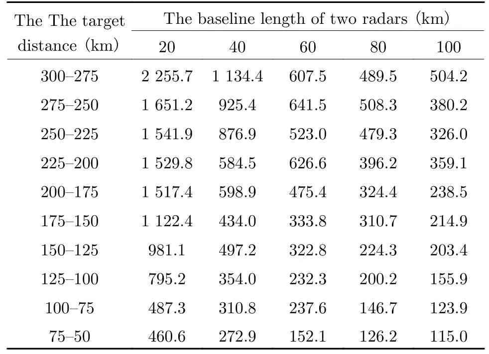
Tab.3 The comparison of the positioning RMSE in X direction in different baseline lengths for two radars(σR1 = σR2 =100 m)m
Further, when the baseline length of two radars is 40 km, change the ranging accuracy of two radars toσR,andσRis equal to 10 m, 30 m,60 m, and 100 m respectively, the Fig.6 shows the target positioning RMSE comparison results inXOZplane under the corresponding error space angle interval.
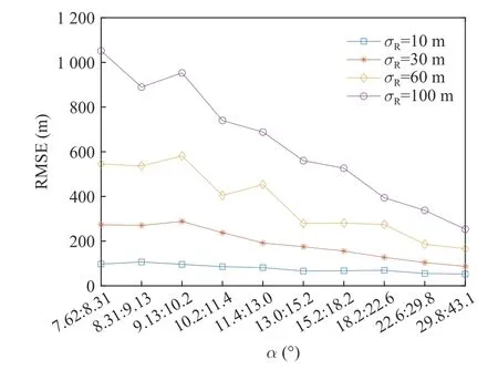
Fig.6 Positioning RMSE analysis in XOZ plane
In the Fig.6, each error space angle interval from small to large corresponds to each 25 km target distance segment that target distance gradually decrease.It is obviously that when the baseline length of two radars is fixed, the closer the target is to radar 1 and radar 2, the larger the angle between error spaces and the higher the positioning accuracy inXOZplane.In the same way, the higher the ranging accuracy of two radars, the better the positioning effect of the algorithm inXOZplane.
From the analysis in Section 3.3 and the geometric relationship, it can be concluded that the angle between two radars and the target is equal to the angle of the error space.The improvement of dual-station positioning accuracy is related to the layout between radars and the target distance, which determine the size of the angle between error spaces.
Therefore, in order to evaluate the positioning effect of the algorithm proposed in this article, for example, the ranging accuracy of two radars is 10 m, under different error space angles,Fig.7 shows the theoretical maximum positioning error inXOZplan.

Fig.7 Positioning performance analysis in XOZ plane
In the Fig.7, it can be observed that when two radars detect the target vertically, the angle between the error spaces is 90°, the precision of collaborative positioning is the highest.And the smaller the error space angle is, the higher the positioning accuracy of targets in theXOZplane is, which also once again verified the previous simulation analysis results.
Finally, different simulation results show that when the baseline length of two radars is 40 km,if the ranging accuracy is 60 m and the accuracy of angle measurement is 0.5°, within the radar's main working range (350 km), the positioning RMSE inXdirection andXOZplane are less than 500 m.
5 Conclusion
In summary, to address the difficulties and low accuracy of long-distance target positioning,through the collaborative detection of multiple radars(T/R) networking, taking advantage of the complementary characteristics of the measurement error space, a fusion localization is proposed.Compared with the traditional DWF algorithm and the FBDWF algorithm, it not only effectively eliminates the influence of systematic error in the azimuth direction, but also has the better positioning accuracy in the azimuth direction andXOZplane.Of course, since the proposed algorithm does not use matrices for calculation and does not need to calibrate the systematic error in the azimuth direction, it also has advantage of low computational complexity.
Furthermore, for the application scenarios of the algorithm proposed, such as multi-radar collaborative positioning and multi-sensor data compression filtering in centralized information fusion, in order to ensure the effectiveness of the algorithm and according to the target orientation and distance required to be detected, suitable radar deployment should be selected to make the error space angle larger, which will also make the positioning accuracy of the algorithm higher in target azimuth and horizontal plane.Finally, for the algorithm proposed in this article,it is recommended that using radar with higher ranging accuracy and the baseline length between radars is 20-100 km.
In the future, for the purpose of eliminating the influence of noise and fluctuation error in azimuth direction, the target error distribution after fusion localization will be considered for the filtering algorithm, which will be designed to further improve the algorithm performance.And it is worth nothing that the proposed algorithm in the pitch direction has basically not been improved.However, when no less than three radars are used for horizontal and vertical networking for collaborative detection, it can simultaneously improve the positioning accuracy in the pitch and azimuth directions.
杂志排行
Journal of Beijing Institute of Technology的其它文章
- Robust Space-Time Adaptive Track-Before-Detect Algorithm Based on Persymmetry and Symmetric Spectrum
- Detection of UAV Target Based on Continuous Radon Transform and Matched Filtering Process for Passive Bistatic Radar
- An Efficient Radar Detection Method of Maneuvering Small Targets
- A Novel Clutter Suppression Algorithm for Low-Slow-Small Targets Detecting Based on Sparse Adaptive Filtering
- Equalization Reconstruction Algorithm Based on Reference Signal Frequency Domain Block Joint for DTMB-Based Passive Radar
- WSN Mobile Target Tracking Based on Improved Snake-Extended Kalman Filtering Algorithm
