Equalization Reconstruction Algorithm Based on Reference Signal Frequency Domain Block Joint for DTMB-Based Passive Radar
2024-03-18ShuaiMaZeqiYangHuaZhangYihengLiuXiaodeLyu
Shuai Ma, Zeqi Yang, Hua Zhang, Yiheng Liu, Xiaode Lyu
Abstract: Channel equalization plays a pivotal role within the reconstruction phase of passive radar reference signals.In the context of reconstructing digital terrestrial multimedia broadcasting(DTMB) signals for low-slow-small (LSS) target detection, a novel frequency domain block joint equalization algorithm is presented in this article.From the DTMB signal frame structure and channel multipath transmission characteristics, this article adopts a unconventional approach where the delay and frame structure of each DTMB signal frame are reconfigured to create a circular convolution block, facilitating concurrent fast Fourier transform (FFT) calculations.Following equalization, an inverse fast Fourier transform (IFFT)-based joint output and subsequent data reordering are executed to finalize the equalization process for the DTMB signal.Simulation and measured data confirm that this algorithm outperforms conventional techniques by reducing signal errors rate and enhancing real-time processing.In passive radar LSS detection, it effectively suppresses multipath and noise through frequency domain equalization, reducing false alarms and improving the capabilities of weak target detection.
Keywords: passive radar; frequency domain equalization; reference signal reconstruction; digital terrestrial multimedia broadcasting (DTMB)
1 Introduction
Passive radar systems, which utilize illuminators of opportunity signals for target detection and tracking while insteading of emitting electromagnetic waves themselves, offer covert and the capability for low-altitude detection, particularly suited for the detection of low-slow-small (LSS)targets [1-3].Various illuminators of opportunity are available, with current research focusing on FM broadcast signals [4, 5], satellite signals[6], LTE signals [7, 8], etc.Digital broadcast signals are increasingly emerging as the preferred choice for ideal illuminators of opportunity in passive radar systems, owing to their broad bandwidth and robust anti-interference properties.Presently, ongoing research in the field of illuminators of opportunity signals encompasses digital audio broadcasting (DAB) [9-11], digital video broadcasting-terrestrial (DVB-T) [12-14],digital terrestrial multimedia broadcasting signals (DTMB) [15-17], etc.This paper uses DTMB signals as illuminators of opportunity.The DTMB signal represents China’s National Standard for digital television, introduced in 2006[18].It currently enjoys extensive coverage across most regions of China and possesses notable attributes including high spectrum efficiency and rapid synchronization capabilities.These features lay the groundwork for research in the field of passive radar predicated on DTMB signals.Comparing with traditional radar systems, passive radar systems rely on reference signals to acquire matching samples during coherent accumulation.However, these reference signals are susceptible to external influences such as environmental and terrain factors, leading to the occurrence of multipath interference.Consequently,the direct application of reference signals and subsequent target echo accumulation post-clutter suppression can adversely impact target detection performance.
Hence, the mitigation of multipath interference within the reference signal becomes crucial.Equalization stands as a key technology in addressing the adverse consequences of multipath interference, constituting a vital phase in the process of reconstructing reference signals.The fundamental concept behind equalization is to generate a characteristic that is the inverse of the channel’s characteristic at the receiver.This inverse characteristic serves the purpose of counterbalancing the multipath effects incurred during signal transmission through the channel, ultimately facilitating the restoration of the original signal.In [19], the study focused on the reconstruction of DTMB passive radar reference signals.This reconstruction process encompassed several crucial steps, including synchronization,channel estimation, equalization, deinterleaving,and decoding.However, it did not provide an indepth elucidation of the specific implementation details concerning the equalization process.In[20], zero-forcing equalization was employed during the reconstruction of CNMB signals.Nevertheless, it is important to acknowledge that when the signal transmission traverses through regions of deep channel fading, the heightened influence of noise can result in a degradation of equalization performance.In [21], a single-carrier frequency domain equalization model was introduced at the receiver, though it did not consider the impact of the input data length.It is crucial to highlight that an excessively long data length during equalization can have adverse consequences on real-time processing.More specifically, when the leading section of the newly received data segment and the trailing portion of the data segment being processed are excessively extended, aliasing may manifest, giving rise to inter-code crosstalk and, subsequently, affecting the overall equalization performance.
Based on this, the present study introduces a novel frequency domain block joint equalization algorithm, which is rooted in the structural attributes of the DTMB signal frame.This algorithm draws from existing frequency domain equalization techniques and capitalizes on the inherent structure of DTMB signal frames.Specifically, it reconfigures the delay and frame structure of each DTMB signal frame to establish a circular convolution block, facilitating parallel FFT calculations.Subsequently, equalization is executed through a dedicated equalizer within this framework.This innovation contributes to enhanced real-time processing capabilities and reduced signal error rates.Following frequency domain equalization of the DTMB signal, the algorithm presented in this paper effectively mitigates the adverse effects of multipath interference and noise.In subsequent passive radar LSS target detection, it significantly diminishes the occurrence of false alarms and robustly detects weak targets.Measured data processing validates the efficacy of this algorithm.Furthermore, it’s noteworthy that this algorithm relies solely on frame header information, necessitating minimal a priori data, and exhibits low computational complexity.
2 DTMB Signal Structure
DTMB signal transmission is classified into two modes: single-carrier and multi-carrier modes.This study focuses on the DTMB signal in the multi-carrier mode, characterized by a multilayer multi-frame structure.At the fundamental level, the signal frame serves as its elementary component.This signal frame comprises two essential segments: the frame header and the frame body.The frame header is constructed from a pseudo-random sequence composed of PN codes.Chinese national standards specify three distinct frame header modes, namely PN420,PN595, and PN945, comprising 420, 595, and 945 symbols, respectively.Meanwhile, the frame body consists of 3 780 symbols.This paper adopts the PN420 frame structure, as depicted in Fig.1.
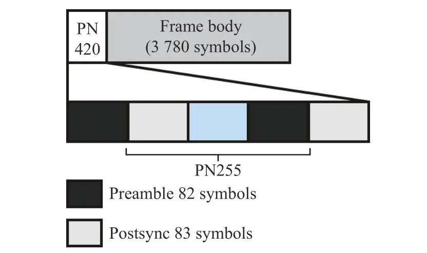
Fig.1 Schematic diagram of PN420 frame structure
The complete time-domain expression of the DTMB signal frame can be mathematically represented as following formula, whereNgrepresents the length of the frame header,N0represents the length of the frame body, PN(n) represents the PN sequence of the frame header,kis the carrier frequency sequence number,s(k) is unmodulated data.
In cases where the PN sequence type of the transmitter signal is pre-determined, PN(n) can be generated locally by the receiver, conforming to the same PN sequence as that of the transmitter signal.This synchronization between the receiver and transmitter signals is vital for precise signal synchronization and channel estimation.The outcomes of channel estimation will subsequently be incorporated into the equalization process, and the only a priori information used at this time is the known frame header information.Section 3.2 of this paper will provide a comprehensive exploration of this process.
3 Reference Signal Reconstruction
3.1 Refactoring Process
Adhering to the signal characteristics of the reference signal allows for the attainment of a reference signal with heightened purity through the process of reconstruction.Reconstruction involves several pivotal steps at the receiving end, including synchronization, channel estimation, equalization, deinterleaving, and demapping of the signal.Subsequently, the purified bitstream is decoded to yield the refined data, and finally regenerate the reference signal, following the same procedural steps employed during signal transmission at the transmitter.
Furthermore, the reconstruction process is categorized into two domains, namely the signal domain and the symbol domain, contingent upon the specific processing objectives.Fig.2 illustrates the comprehensive reconstruction process.In this paper, particular emphasis is placed on signal domain reconstruction, with the primary research focus directed towards the enhancement of channel equalization methodologies.
3.2 Synchronization and Channel Estimation
Following the filtering and matching of the signal at the receiving end, the initial step involves synchronization.This synchronization procedure leverages the favorable autocorrelation properties inherent in the PN frame header sequence.The DTMB signal frame header type selected in this paper is PN420 cyclic shift type.The synchronization process can be based on the good autocorrelation characteristics of the PN header sequence by using the locally generated PN sequence to perform cross-correlation operations on the received sequence.Calculate the peak position of the cross-correlation function, which is also the position of the frame header of each frame in the DTMB signal, to achieve frame synchronization of the DTMB signal.The process can be expressed as
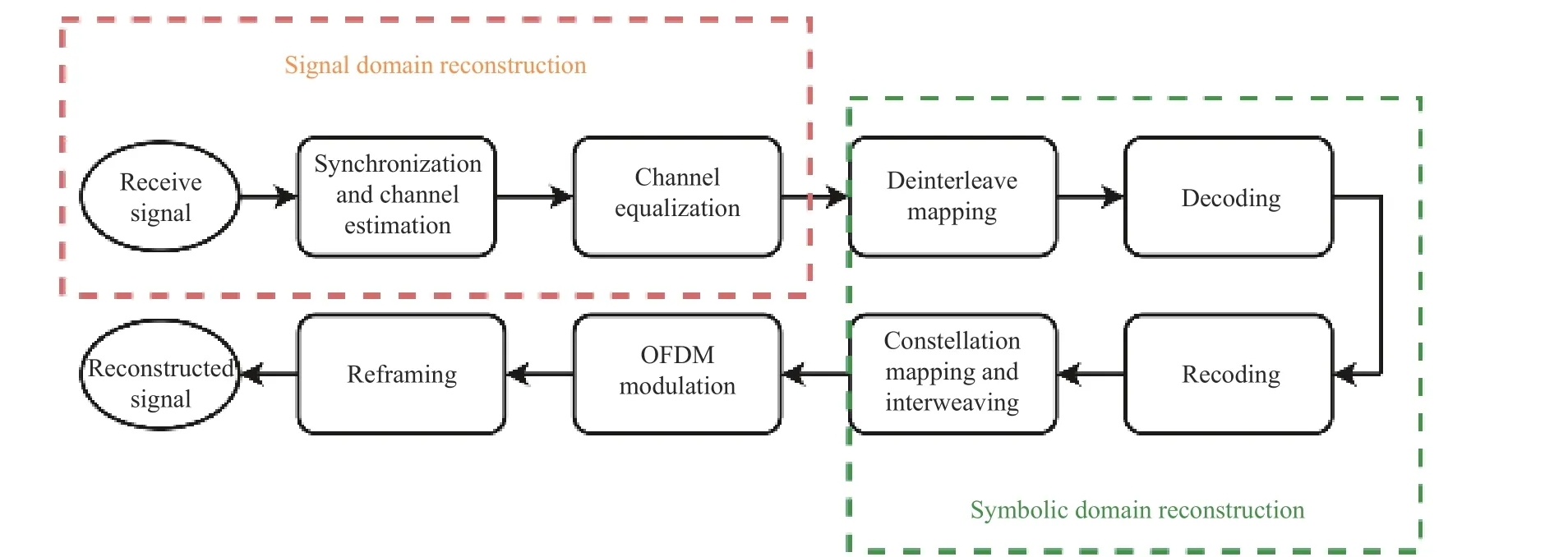
Fig.2 The process of signal domain and symbol domain reconstruction
whereS(n) represents the signal input to the synchronization process, PN(i) denotes the local PN sequence with a length ofNg, the superscript * signifies the conjugate operation, andR(S,PN)represents the resultant cross-correlation function.
Fig.3 illustrates synchronization result chart derived from a set of test data, it can be seen that the synchronization peaks are obvious, and the length between each peak is the length of one signal frame (PN420 + 3 780 symbols of frame body information, 4 200 symbols in total).
Subsequently, by leveraging the interrelation between cyclic codes preceding and following the PN sequence within the frame header,carrier frequency synchronization can be achieved.The pertinent mathematical expressions are illustrated as follows
wherex1(n) andx*2(n) respectively represent the same parts corresponding to the cyclic expansion before and after the frame header,Ndis the number of sampling points between the before and after cyclic expansion parts, Δfrepresents the frequency offset estimate of the carrier,Nrepresents the length of the sequence, andLsrepresents the symbol length.
The channel estimation in DTMB utilizes a specific pilot, namely a locally generated PN sequence, to estimate the transmission characteristics of the channel.At this point, the channel transmission model can be represented as
whereHrepresents the impulse response of the channel, PNinrepresents the input PN sequence into the channel,Youtdenotes the output signal after traversing through the channel, andNrepresents additive Gaussian white noise.
Utilize the least squares criterion to estimate the impulse responseHof the channel,with the objective function depicted as
where the superscriptHrepresents the conjugate transpose,represents the signal output obtained after estimation, andis the estimated channel response.Following the least squares criterion, we calculate the partial derivative ofand equate it to zero to determine the minimum value of the objective function.At this juncture, the estimated channel response is given by
3.3 DTMB Signal Equalization
3.3.1 Traditional Model of Equilibrium Algorithm
The transmission system, as depicted in Fig.4.LetX=[x(1),x(2),...,x(k)]Tdenote the data transmitted over the channel, wherex(k) signifies thek-th data segment transmitted through the channel.Y=[y(1),y(2),...,y(k)]Trepresents the data received by the receiving end, withy(k)denoting thek-th signal received by the receiving end.The signal is transmitted through the channel and before equalization can be expressed as
where⊗represents circular convolution.h=[h1,h,...,h]Tis the impulse response of the chan-
2
Lnel, andnrepresents the additive Gaussian white noise with a mean value of zero.
In Fig.4, it can be seen that for the traditional equalization model, an entire block of data is transmitted through the channel and subsequently subjected to a frequency domain transformation.Subsequently, this transformed data directly passes through the equalizer to mitigate the influence of the channel impulse responseh.The length of the data segment in this process determines the number of points in the FFT transformation.In practical applications, the volume of data transmitted through the channel is often substantial, leading to a considerable computational load for the overall FFT calculations.Consequently, the system necessitates high realtime processing capabilities.If real-time processing lags, it can result in aliasing, causing the front portion of the newly received data segment to overlap with the tail portion of the data segment currently being processed.This aliasing phenomenon leads to inter-code crosstalk and significantly impacts equalization performance, as illustrated in Fig.5.
3.3.2 The DTMB Signal Equalization Algorithm Proposed in This Paper
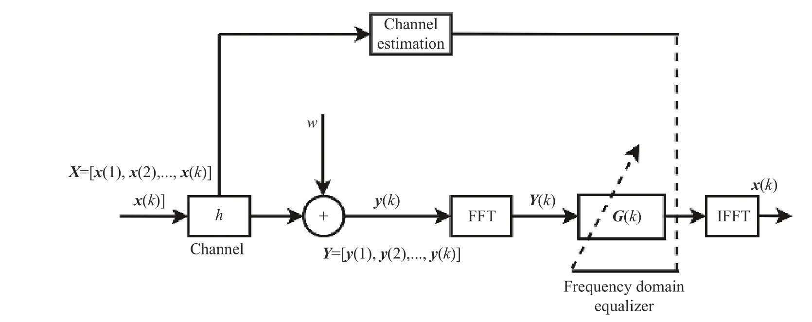
Fig.4 Channel transmission and frequency domain equalization model
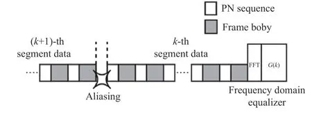
Fig.5 Schematic diagram of traditional equilibrium model data processing aliasing
For DTMB signals, the volume of data transmitted through the channel is substantial.In order to fulfill the real-time processing demands of the system and mitigate the adverse effects of aliasing, this paper introduces a frequency domain block joint equalization algorithm grounded in the structural characteristics of DTMB signal frames.The core concept involves leveraging the DTMB signal frame structure and its inherent properties in channel transmission.Specifically,the delay associated with the frame header of each DTMB signal frame is segmented into blocks to create circular convolution blocks.Subsequently, FFT calculations are performed in parallel for each data block, followed by IFFT processing post-equalization through a dedicated equalizer.Finally, the output data blocks are reassembled to culminate in the completion of the DTMB signal equalization process.
The block structure designed for DTMB signals in this study is illustrated in Fig.6.During the transmission of DTMB signals through the channel, delay expansion phenomena are observed, primarily resulting from multipath interference and inter-code crosstalk.These phenomena lead to the displacement of the frame header from thei-th frame into the frame body and the intrusion of thei-th frame body into the frame header of the (i+1)-th frame.
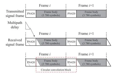
Fig.6 Fast block circular convolution step based on DTMB signal
Since the properties of DTMB frame headers of the same type are identical, an opportunity exists to construct a circular convolution block by rearranging the frame header and frame body, provided that the multipath delay expansion within the block does not exceed the length of the frame header.In contrast to conventional blocking methods, this article employs a specific approach wherein a circular convolution block is formed by combining the frame body of thei-th frame (3 780 symbols) with the frame header of the (i+1)-th frame (420 symbols).The conventional blocking method, on the other hand,entails creating a circular convolution block using the frame header and frame body of thei-th frame, as depicted in Fig.7.
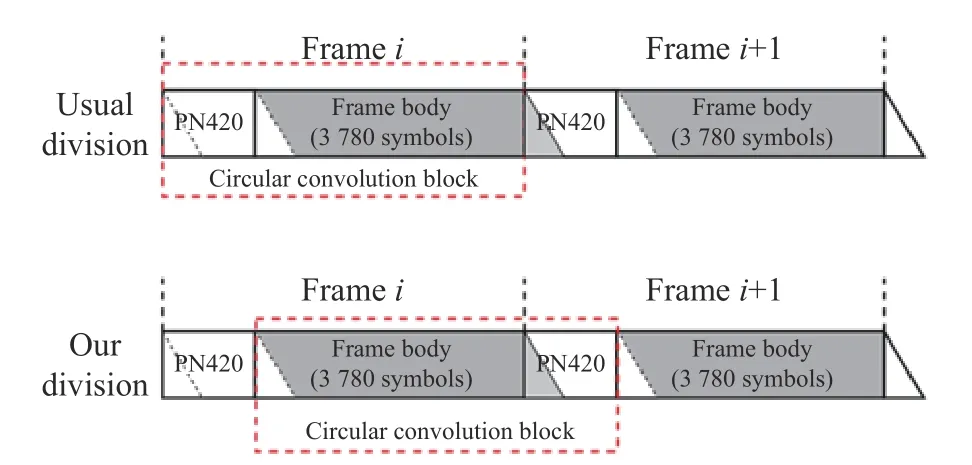
Fig.7 Comparison between this article’s blocking and conventional blocking
Owing to the impact of multipath delay expansion within the frame header, the conventional blocking method encounters a challenge where a portion of the frame body information is lost, consequently detrimentally affecting equalization performance.In contrast, the approach presented in this paper effectively preserves all frame information.Within this method, aliasing is observed at the head of the circular convolution block, which can be interpreted as the cyclic continuation of the PN sequence occurring at the block’s end.The postponement of the data pertaining to the body of thei-th frame is protracted to the frame header section of the (i+1)-th frame.The circular convolution block established within this study encompasses the data from this delayed extension.Following the block equalization process and subsequent data rearrangement, it becomes feasible to preserve the entirety of the frame-related information, thereby mitigating the occurrence of bit errors.The approach presented in this paper effectively preserves all frame information and will not change the information of the original data, which is also universal for all PN420 types.This distinctive characteristic contributes to the preservation of the complete frame information, enhancing the effectiveness of equalization procedures.
Therefore, the joint equalization algorithm based on frequency domain blocking proposed in this article can be described as follows.
Step 1 First, divide the receivedk-th segment of data with lengthPinto blocks, and each block’s length corresponds to the length of a single frame of the signal.In the case of this paper,it’s pertinent to note that the frame header is PN420, with a sampling rate of 7.56 MHz.Consequently, the total length of the combined frame header and frame body isQ=4 200 symbols.Assuming the total number of blocks is denoted asn, then the relationship betweennandPcan be expressed asn=P/Q.Thus, the representation of thek-th data segment transmitted through the channel becomes
wherexkrepresents thei-th signal frame, which can also be called thei-th circular convolution block.Thei-th frame in the receivedk-th segment of data can be expressed as
Step 2 Subsequently, perform FFT on theith frame’s signal, resulting in the following outcome
whereYk(i),Hk,Xk(i),N(i) corresponds to their respective FFT transformation.The result of FFT of the entire data can be expressed as
Step 3 Each frame’s signal, following its frequency domain transformation, is concurrently processed through the frequency domain equalizer.The equalizer’s structural representation is depicted in Fig.8.Notably, this enhanced equalizer builds upon the design of the equalizer illustrated in Fig.4, incorporating signal blocking,parallel computing, and signal combination modules.This modification facilitates swift blockbased equalization in the frequency domain,enhancing overall processing efficiency.
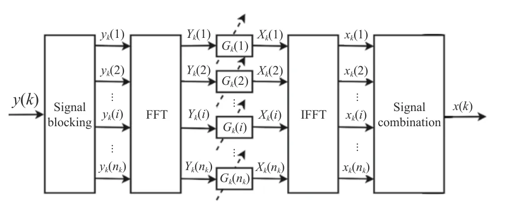
Fig.8 Frequency domain block joint equalizer structure diagram
Assuming that the equalization coefficient matrix isGk(i) , the outputXˆk(i) of thei-th frame signal in the frequency domain after equalization can be expressed as
Since each frame of signal is transmitted through the same channel, soGk(1)=Gk(2)=···=Gk(i)=Gk, the outputXˆ(k) of the entire data after frequency domain equalization can be expressed as
In order to solve the coefficient matrixGk,the minimum mean square error (MMSE)method can be used here.Suppose the mean square error between the equalized signal and the original data signal is MSE, then
Under MSE conditions, it is required to minimizeGkso that MSE is minimized.Since the signal remains uncorrelated with the noise throughout the transmission process, the result of the formula above can be expressed as
This also can be expressed as
whereHˆ is the channel characteristics estimated in the channel estimation, it can be seen in (7)and SNR is the signal-to-noise ratio of the transmission signal.
Step 4 Conduct IFFT on each frame of the signal after equalization.Ultimately, combine each signal block to derive the outputxˆ(k) for thek-th data segment across the entire time domain following frequency domain equalization.This process is illustrated as
whereiranges from 1 ton.Assuming m signifies the total number of received data segments, the data received throughout the entire process can be represented as
Consequently, by following the aforementioned procedure, the reconstruction of the DTMB signal in the signal domain can be achieved.Subsequently, the signal can undergo deinterleaving, mapping, decoding, and re-encoding to reconstruct the symbol domain.It is worth noting that this aspect of the process is underpinned by relatively mature technologies and processes [19,20], which are not the primary focus of this article and, therefore, will not be explored in detail here.
4 Simulation Analysis
4.1 Multipath Suppression Simulation
The DTMB signal is generated through simulation as a reference signal.This signal exhibits a bandwidth of 7.56 MHz, a sampling rate of 10 MHz, and employs the PN420 frame header mode.In the simulation, the signal traverses the Rayleigh channel, introducing multipath delays and power attenuation.The parameters governing the multipath signal are detailed in Tab.1.As a result, the signal-to-clutter ratio (SCR) for the reference signal stands at approximately 11.01 dB.Subsequently, the frequency domain block joint equalization algorithm, as proposed in this article, is applied to reconstruct the signal domain from the mixed multipath reference sig-nal.This evaluation serves to assess the algorithm’s capability to effectively suppress multipath interference.

Tab.1 Multipath signal parameters
As the reference signal and the multipath signal exhibit a significant correlation, both the reference signal before and after equalization using this algorithm can be subjected to autocorrelation to generate the correlation peak spectrum.The algorithm’s effectiveness in suppressing multipath interference is evaluated by its capacity to attenuate the secondary peaks, leaving only the central peak in the spectrum, as depicted in Fig.9.

Fig.9 Reference signal autocorrelation peak diagram: (a) signal autocorrelation peak diagram before algorithm processing; (b) signal autocorrelation peak diagram after algorithm processing
As the autocorrelation peak for the same signal is symmetrical about the 0 point, the outcomes for the positive and negative half-axes are identical.In practical scenarios, only the half-axis is typically considered.In this analysis, the delay unit exclusively pertains to the positive half-axis.
Fig.9(a) illustrates that the presence of multipath leads to the emergence of secondary peaks in the autocorrelation peak spectrum.Each multipath condition detailed in Tab.1 is also annotated in the figure.Fig.9(b) demonstrates that, following the application of the algorithm presented in this paper, the multipath-induced secondary peaks within the autocorrelation peak spectrum have been significantly mitigated, effectively suppressing multipath interference.At this juncture, the SCR for the reference signal stands at 16.57 dB, marking an increase of approximately 5.46 dB in the SCR.This outcome underscores the algorithm’s efficacy in multipath interference suppression.
4.2 Algorithm Bit Error Rate Performance Simulation
This section aims to validate the impact of the algorithm proposed in this article on the bit error rate (BER) under conditions characterized by a low signal-to-noise ratio and the presence of additive white Gaussian noise (AWGN) within the channel.The statistical association between the BER and the signal-to-noise ratio (SNR) of the reference signal for DTMB signals subjected to 4QAM modulation is examined.This analysis considers signals processed through both the frequency domain block joint equalization algorithm introduced in this paper and a conventional equalization algorithm.The comparative results are depicted in Fig.10.

Fig.10 The relationship between the BER of the algorithm in this paper and the traditional algorithm changes with the SNR
Evidently, in conditions characterized by a low SNR, the algorithm proposed in this article exhibits a lower BER in comparison to the traditional algorithm.This outcome can be attributed to the fact that during the equalization process of the traditional algorithm, aliasing occurs between the front section of the newly received data segment and the trailing portion of the data segment currently being processed.This aliasing phenomenon results in inter-code crosstalk,adversely affecting equalization performance.The integration of blocking and joint equalization in the proposed algorithm enhances real-time processing capabilities and mitigates this adverse effect.As the SNR increases, this advantage becomes more pronounced, which also shows that the algorithm proposed in this paper has better ability to resist noise.
5 Measured Data Verification
The National Key Laboratory of Microwave Imaging Technology of the Aerospace Information Research Institute, Chinese Academy of Sciences, have conducted several experimental studies on passive radar detection of drones based on DTMB in Beijing in 2022.The test uses the CCTV Tower in Haidian District, Beijing as the illuminators of opportunity, the frame header mode is PN420, the center frequency is 674 MHz,and the system sampling rate is 10 MHz.
In the experiment, data was collected from the measured information of the reference channel and echo channel.A 0.1 s segment of received data was selected, known to contain a weak target.Two sets of data were used for further analysis: the unpurified reference signal and the reference signal and echo signal that were purified using the algorithm proposed in this paper.Mutual ambiguity calculations were conducted for both data sets, and the results were used to obtain range-Doppler outcomes for the purpose of validating the effectiveness and practicality of the algorithm.The range-Doppler results pertaining to the detection of LSS targets are depicted in Fig.11.
Fig.11(a) and Fig.11(b) illustrate the outcomes of LSS target detection when employing the unpurified reference signal directly and the echo signal.Notably, these figures depict a considerable level of multipath and noise interference present in the data.Consequently, numerous clutter spikes are evident on the range profile and the range-Doppler three-dimensional map.Furthermore, the target becomes obscured,rendering it impossible to detect and accurately locate the real target.This situation gives rise to false alarms and missed alarms.
Fig.11(c) and Fig.11(d) present the results of LSS target detection utilizing the reference signal reconstructed by the algorithm proposed in this paper, in conjunction with the echo signal.Notably, these figures demonstrate that a substantial portion of the clutter peaks observed in the range profile and the range-Doppler threedimensional diagram has been successfully suppressed and significantly attenuated.Additionally, the correlation peak spectrum of the target has been notably reinforced, as clearly depicted in the figures.Consequently, the weak target is successfully detected under these conditions.
These results underscore the capacity of the reference signal reconstruction, enabled by the algorithm in this paper, to effectively mitigate strong multipath interference and noise interference within the reference signal channel of the received data.This, in turn, enhances the performance of passive radar LSS target detection.Furthermore, the results validate the accuracy and effectiveness of the method introduced in this paper.
6 Conclusion
This paper introduces a novel frequency domain block joint equalization algorithm predicated on the distinctive structure of the DTMB signal.This algorithm based on the foundations of established frequency domain equalization techniques while leveraging the specific characteristics of the DTMB signal frame structure during the channel transmission process.Comparing with conventional blocking methodologies, this approach rearranges the frame body by accommodating the delay of each frame header within the DTMB signal, thereby forming circular convolution blocks.Parallel FFT calculations are performed, followed by IFFT output via an equalizer.Subsequently, the output block data is recombined to conclude the DTMB signal equalization process.Both simulation and theoretical analysis reveal that, comparing with conventional equalization algorithms, the method proposed herein effectively reduces the BER and bolsters real-time processing capabilities.Measured data further confirm the algorithm's effectiveness in mitigating multipath and noise following frequency domain equalization of DTMB signals.In the context of passive radar LSS target detection,the algorithm mitigates false alarms and enables the reliable detection of weak targets.
杂志排行
Journal of Beijing Institute of Technology的其它文章
- Improved Weighted Local Contrast Method for Infrared Small Target Detection
- WSN Mobile Target Tracking Based on Improved Snake-Extended Kalman Filtering Algorithm
- A Novel Clutter Suppression Algorithm for Low-Slow-Small Targets Detecting Based on Sparse Adaptive Filtering
- An Efficient Radar Detection Method of Maneuvering Small Targets
- Detection of UAV Target Based on Continuous Radon Transform and Matched Filtering Process for Passive Bistatic Radar
- Robust Space-Time Adaptive Track-Before-Detect Algorithm Based on Persymmetry and Symmetric Spectrum
