Scheme of negative acoustic radiation force based on a multiple-layered spherical structure
2024-01-25MenyangGong宫门阳XinXu徐鑫YupeiQiao乔玉配JiehuiLiu刘杰惠AijunHe何爱军andXiaozhouLiu刘晓宙
Menyang Gong(宫门阳), Xin Xu(徐鑫), Yupei Qiao(乔玉配),Jiehui Liu(刘杰惠), Aijun He(何爱军), and Xiaozhou Liu(刘晓宙),4,‡
1Key Laboratory of Modern Acoustics,Institute of Acoustics and School of Physics,Collaborative Innovation Center of Advanced Microstructures,Nanjing University,Nanjing 210093,China
2School of Physics and Electronic Science,Guizhou Normal University,Guiyang 550001,China
3School of Electronic Science and Engineering,Nanjing University,Nanjing 210023,China
4State Key Laboratory of Acoustics,Institute of Acoustics,Chinese Academy of Sciences,Beijing 100190,China
Keywords: acoustic tweezers,negative acoustic radiation force,particle manipulation
1.Introduction
Ashkin proposed the concept of “optical tweezers” to achieve precise manipulation of microscopic particles, and therefore won the Nobel Prize in 2018.To overcome the shortcomings of optical tweezers in terms of scale and thermal effect,[1]Wu proposed “acoustic tweezers” based on acoustic radiation force(ARF).[2]Some ideas for building acoustic tweezers have gradually been proposed.[3–5]The generation of ARF is based on the nonlinear effect of the sound field.Through this effect, the momentum and angular momentum transfer can be realized between the sound field and the particles.Compared with the traditional particle manipulation method,ARF has a very significant advantage: The manipulation process is non-contact.Therefore,the ARF has gained extensive attention and wide application in ultrasound medicine and particle control.The research and investigation of the law of ARF are of great important significance.The ARF of standard particles such as cylindrical particles and spherical particles in the plane wave field or Bessel beams has been studied in detail.[1,2,6–16]The effects of ARF on particles in viscous media have also been included in the investigations.[17]ARFs with normal closed boundaries have been studied.[18,19]The ARF of standard particles in non-diffracted waves has also been investigated.[20]Resonant adhesion structure has been studied to make negative ARF.[21]Based on the angular spectrum and multipole expansion, the calculation methods of acoustic radiation force and moment have been further developed.[22,23]The sound field of the spherical shell structure has been analyzed and proved to be a meaningful attempt.[24–27]Some schemes of manipulating particles are carried out by using acoustic streaming.[28–30]In the field of acoustic manipulations,some of important progress have been made.[31–33]Recently,the influence of cavity and interface on ARF has been evaluated.[34–36]
The concept of“acoustic tweezers”emphasizes the construction of acoustic potential wells for particle manipulation and trapping.In actual scenes,the sound source is often confined to a small angle relative to the particles.Therefore, it is of great significance to realize the negative ARF based on a unidirectional or small-angle sound beam.However, based on the definition, the negative ARF represents that the structure in the sound field is subjected to a force towards the sound source, which is extraordinary and difficult to achieve by traditional methods.Gonget al.[37]previously proposed a solution to the negative ARF of a single acoustic beam based on non-diffracted waves.In the calculation of the Bessel beam, Marston mentioned that based on the suppression of backscatter,it is possible to realize the negative ARF.[38]The first numerical demonstration of the negative ARF by suppressing the backscattering of non-spherical objects was performed by Gonget al.[39]Therefore, in this work, the design of suppressing the backscattering of the controlled structure is considered to explore the possibility of the negative ARF of the unidirectional sound beam acting on the structure.The sound field analysis of core–shell particles has been analyzed by Leibacheret al.[40]In this paper, the structure is designed to achieve suppression of backscattering.After a lot of parameter verifications and numerical simulations, a structure that exhibits negative ARF effects in a specific frequency spectrum has been successfully found.This demonstrates the feasibility of achieving negative ARF by suppressing backscattering.
2.Analysis of multi-layered spherical structure
Due to the limitations of most practical application scenarios,the structure design needs to be as independent as possible from the angle parameter and only related to the radial coordinates.Majid Rajabiet al.achieved acoustic radiation force control by pulsating spherical carriers in 2017,[41]which has been proved as an effective way.Therefore, the use of a multi-layered spherical structure to design the distribution of acoustic parameters is considered.

Fig.1.Discrete multi-layered spherical structure in sound field.The source is a unidirectional monochromatic wave.
In the design and implementation process, the multiplelayered structure is generally described in a differential manner.Therefore, in calculations, the multiple-layered structure is discretized into a multiple-layered spherical shell as shown in Fig.1.All kinds of unidirectional sound beams can be expanded into a linear combination of plane waves.Therefore,the incident beam considered in the calculation is a plane wave.Since the multi-layer spherical shell structure subjected to radiation force is a spherical symmetrical structure, the plane wave can be expanded in spherical coordinates.Since ARF calculation will be time-averaged,the frequency domain expression is used.Incident waveΦican be expressed as follows:
whereΦk0is the incident velocity potential,k0is the wavenumber of the sound wave in the external environment medium,jnis the first kind of spherical Bessel function of ordern,Pnis the Legendre function of ordern.
Similarly, the scattered waveΦscan also be expanded into a linear combination of spherical waves
whereAn,sis the coefficient of scattered sound wave,is the Hankle function of the first kind of ordern.
Therefore,the total sound field sound pressureΦ0in the environmental medium can be expressed as
For the reason that the sound wave needs to propagate to the interior of the controlled structure, the elastic boundary conditions should be taken between the medium and the structure,and between the middle and layers of the structure.There is mode conversion at the boundary,so the medium particle displacement satisfies the Navier equation
hereλandµare the Lami coefficient,
Because the boundary conditions are described by velocity continuity,the internal sound field is also described by velocity potential to unify the expression.Since the sound field will form a stable sound field structure after incident for a period of time,it is only necessary to sort out the general form of velocity potential expression,and obtain the undetermined parameters by boundary conditions in the form of undetermined coefficients.
For the first layer of medium, the velocity potential of longitudinal wave can be expressed as
hereΦk0is velocity potential constant, nnis Neumann function,An,1aandAn,1bare pending parameters,k11is the longitudinal wavenumber in the spherical layer 1.
The transverse wave velocity potential
Similarly,for the velocity potential in theq-th layer,longitudinal wave velocity potential:
then transverse wave velocity potential
whereAn,qa,An,qb,An,qc, andAn,qdare pending parameters,kq1andkq2are the longitudinal wavenumber and transverse wavenumber in theq-th spherical shell individually.If theqth layer is the innermost layer,the Neumann function item returns to zero, and the velocity potential in theq-th spherical shell is given below.
The longitudinal wave velocity potential can be written as
The transverse wave velocity potential can be written as
For the discretized multi-layered spherical structure ofmlayer,there are 4(m−1)+3=4m−1 independent boundary condition equations,and 4m+1−2=4m−1 undetermined coefficients need to be determined.Therefore,this system of equations is mathematically solvable.Then, the boundary conditions of this structure will be analyzed in detail.
The specific continuity equations and the expansion of the corresponding parameters are given below.
(i) Boundary conditions between the first layer structure and the external medium
The normal displacement continuity:
The normal stress continuity:
whereΦis the velocity potential of the longitudinal wave andΨis the velocity potential of the transverse wave.
(ii)Boundary conditions between theq-th layer structure and the(q+1)-th layer structure
The normal displacement continuity:
The tangential displacement continuity:
The normal stress continuity:
The tangential stress continuity:
where,ur,qis the radial component of the particle vibration velocity in layerq,uθ,qis the angular component of the particle vibration velocity in layerq,Φqis the longitudinal velocity potential in layerq,Ψqis the transverse velocity potential in layerq.To determine the undetermined coefficients,we organize them into a matrix solution:AN=A1N/A2N.For m-storey structure,both matrices are(4m−1)×(4m−1)matrices.The specific expression of the matrix is shown in the appendix.
Thus,the velocity potential field information scattered by the multi-layered spherical structure is obtained.Based on definition,the expression of the ARF on the multi-layered spherical structure can be expressed as
wherezis the propagation direction of the incident sound beam andsis the surface of the geometrical surface of the particles.
Based on Eqs.(1)–(16),the velocity potential distribution of the entire sound field can be obtained by means of undetermined coefficients.Then the total velocity potentialΦ0in the external medium can be obtained by Eq.(3).The integral in Eq.(17)including the total velocity potentialΦ0in the external medium is implemented by accumulating the discretized velocity potentials.The expression of the total velocity potentialΦ0includes the position coordinates, which could be further simplified based on symmetry during the accumulation process.
3.Finite element simulation of multi-layered spherical structure
In Section 2, the analytical expression of the ARF received by the multi-layered spherical structure in a unidirectional sound beam is obtained.After a large number of parameter verifications, we find that the specific multi-layered spherical structure can achieve the negative ARF in the unidirectional sound beam sound field.The following structures shown in Fig.2–7 are aluminum–water–aluminum–water alternating multi-layered spherical structures.To further clarify the physical mechanism,as a control,the structures of copper–water–copper–water multi-layered spherical structure in Fig.8 and 9 and PVC(polyvinyl chloride)–water–PVC–water multilayered spherical structure in Figs.10 and 11 are also verified.The relevant parameters are shown in Table 1.
To verify the real existence of back suppression in layered structure design, the finite element simulations based on COMSOL Multiphysics 6.1 are carried out.In all finite element simulations,the radiusRof the multiple-layered spherical structure is set to 0.5 mm.The incident background pressure is set to 1 Pa.The maximum grid size is set to 1/6 of the wavelength,so the sound field distribution could be accurate enough.By means of finite element simulation,the velocity potential distribution of the entire sound field is obtained.Based on the definition formula for the calculation of the ARF Eq.(17),the ARF on the structure can be obtained by performing the corresponding integral on the outside of the controlled structure surface.In the actual calculations, the probe tool of the finite element simulation is applied,and the velocity potential containing the position coordinates is uniformly sampled.With sufficiently dense sampling,the integral is calculated by accumulation, and the differential is calculated by difference method.In practice,this process can be further simplified by symmetry.For example, based on the rotational symmetry of the structure, only the component integration of the ARF in the incident direction of the incident acoustic beam is required.The blue square point in Figs.2, 3, 4, 8 and 10 is obtained due to the frequency sweep of finite element analysis, and the black curve is drawn based on the analytical solution in Section 2.The finite element simulations are carried out in three dimensions.Figures 5–7, 9, 11 are sections through the propagation direction.The innermost hierarchical structure is the multiple-layered spherical structure shown in Fig.1.Due to symmetry,all sound pressure distributions have been shown.The outer dark blue layer in Figs.5–7, 9, 11 is the perfectly-matched layer.The perfectly-matching layer is far enough from the controlled structure to perfectly absorb the sound wave without affecting the distribution of the sound field.It can be seen from the figures that the points obtained by finite element analysis basically fall on the curve of analytical solution,which also confirms the correctness of finite element simulation and analytical solution.
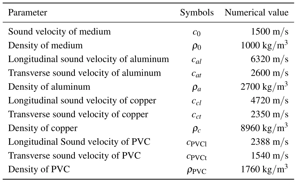
Table 1.Parameters selections.
Firstly,the four-layer structure of 1:3:1:5 is analyzed,and the parameter values are:Rlayer1=R/10,Rlayer2=3R/10,Rlayer3=R/10.the schematic diagram of the variation of ARF with the spectrum is shown in Fig.2.It could be seen that this structure can show obvious negative ARF when subjected to a single sound beam from 0.1 MHz to 3.5 MHz.
For a comparison,as shown in Fig.3,the four-layer structure of 1:1:1:7 is analyzed, and the parameter values are:Rlayer1=R/10,Rlayer2=R/10,Rlayer3=R/10,the schematic diagram of the variation of ARF with the spectrum is shown in Fig.3.We can see that this structure shows a narrow range negative ARF when subjected to a single acoustic beam from 0.1 MHz to 3.5 MHz.
Similarly, as shown in Fig.4, the four-layer structure of 1 : 5 : 1 : 3 is analyzed, and the parameter values are:Rlayer1=R/10,Rlayer2=R/2,Rlayer3=R/10, the schematic diagram of the variation of ARF with the spectrum is shown in Fig.4.We can see that this structure does not show negative ARF when subjected to a single sound beam from 0.1 MHz to 3.5 MHz.
The sound pressure distribution is equivalent to the distribution of the velocity potential.It can be seen from Eq.(17)that the velocity potential is an important factor that directly affects the ARF on the structure.In the previous conjecture proposed by Marston, the negative ARF can be obtained by suppressing backscattering.[38]In Fig.2,this conjecture is realized through a multi-layer spherical structure.In order to illustrate the process of backscattering suppression causing the reversal of ARF more vividly,the sound pressure distribution images based on several key frequency points are drawn.To analyze the mechanism of the generation and disappearance of negative ARF,the multiple-layered spherical structure and its surrounding sound field in the process of frequency scanning are drawn.The sound beam enters from left to right.It can be seen in Fig.5 that when the structure is subjected to negative ARF, a strong scattering region is formed between the inner and outer layers of the structure,and the backscattering is obviously suppressed.Therefore, the structure is subjected to negative ARF.At low frequencies,the formation of this common vibration peak is not obvious, mainly manifested in the positive ARF.At high frequencies, the structure forms multiple scattering peaks,which counteract the effect of producing a scattering region that suppresses the backscattering peaks,and thus also exhibits positive ARFs.
In the four-layer structure of 1:1:1:7 as shown in Fig.6,the peak region of enhanced backscattering is formed synchronously in the process of forming the peak of inhibiting backscattering, and the inhibitory effect on backscattering is not obvious.Therefore,it only shows a narrow negative ARF range.
In the 1:5:1:3 four-layer structure as shown in Fig.7,other multiple scattering peaks are generated almost synchronously in the process of forming the peak of restraining backscattering.Therefore,in this case,the particles are always subjected to positive ARF.

Fig.2.The four-layer structure of 1 : 3 : 1 : 5. Rlayer1 = R/10,Rlayer2 =3R/10, Rlayer3 =R/10.The black solid line is the result of theoretical calculation.The blue point is the result of finite element simulation.The red dotted line is the reference line for the direction change of ARF.The structure is subjected to negative ARF in a specific frequency band.

Fig.3.The four-layer structure of 1 : 1 : 1 : 7. Rlayer1 = R/10,Rlayer2 =R/10, Rlayer3 =R/10.The black solid line is the result of theoretical calculation.The blue point is the result of finite element simulation.The red dotted line is the reference line for the direction change of ARF.The structure shows a narrow range negative ARF.
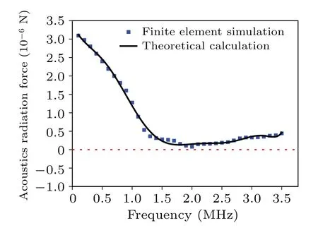
Fig.4.The four-layer structure of 1 : 5 : 1 : 3. Rlayer1 = R/10,Rlayer2 =R/2,Rlayer3 =R/10.The black solid line is the result of theoretical calculation.The blue point is the result of finite element simulation.The red dotted line is the reference line for the direction change of ARF.The structure shows no negative ARF.
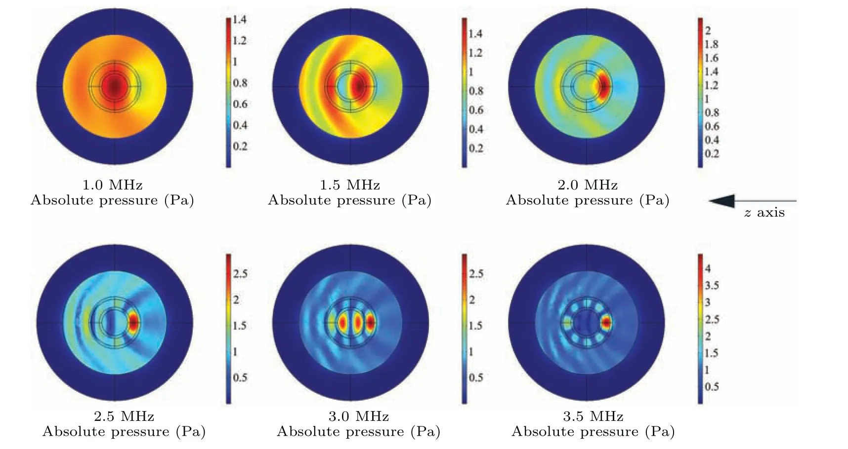
Fig.5.Sound field distribution of multiple-layered spherical structure with four-layer of 1:3:1:5 incident by unidirectional monochromatic wave.The frequency points are 1.0 MHz,1.5 MHz,2.0 MHz,2.5 MHz,3.0 MHz,and 3.5 MHz respectively.

Fig.6.Sound field distribution of multiple-layered spherical structure with four-layer of 1:1:1:7 incident by unidirectional monochromatic wave.The frequency points are 1.0 MHz,1.5 MHz,2.0 MHz,2.5 MHz,3.0 MHz,and 3.5 MHz respectively.
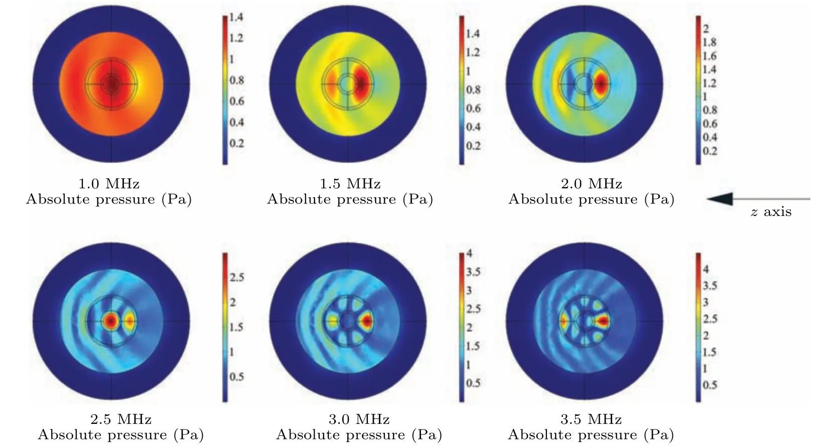
Fig.7.Sound field distribution of multiple-layered spherical structure with four-layer of 1:5:1:3 incident by unidirectional monochromatic wave.The frequency points are 1.0 MHz,1.5 MHz,2.0 MHz,2.5 MHz,3.0 MHz,and 3.5 MHz respectively.
To further clarify the physical mechanism, the structures of copper–water–copper–water multiple-layered spherical structure of 1:3:1:5 is analyzed in Fig.8,and the parameter values are:Rlayer1=R/10,Rlayer2=3R/10,Rlayer3=R/10.the schematic diagram of the variation of ARF with the spectrum is shown in Fig.8.It could be seen that this structure shows no negative ARF.
Similarly, the copper–water–copper–water structure and its surrounding sound field in the process of frequency scanning are drawn in Fig.9.It can be seen that in the interval where the suppression of backscattering should have occurred,the positive peak is generated synchronously.Therefore,only the minimum value of the positive ARF is generated,and there is no reversal of the direction of ARF.

Fig.8.The four-layer copper–water–copper–water structure of 1:3:1:5. Rlayer1=R/10,Rlayer2=3R/10,Rlayer3=R/10.The black solid line is the result of theoretical calculation.The blue point is the result of finite element simulation.The red dotted line is the reference line for the direction change of ARF.The structure shows no negative ARF.

Fig.9.Sound field distribution of copper–water–copper–water multiple-layered spherical structure with four-layer of 1:3:1:5 incident by unidirectional monochromatic wave.The frequency points are 1.0 MHz,1.5 MHz,2.0 MHz,2.5 MHz,3.0 MHz,and 3.5 MHz respectively.
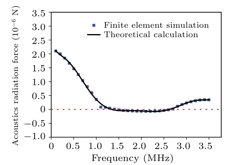
Fig.10.The four-layer PVC–water–PVC–water structure of 1:3:1:5.Rlayer1 =R/10, Rlayer2 =3R/10, Rlayer3 =R/10.The black solid line is the result of theoretical calculation.The blue point is the result of finite element simulation.The red dotted line is the reference line for the direction change of ARF.The structure shows insignificant negative ARF effects in a specific interval.
In addition to metal materials,the structure of organic materials has also been verified.The structures of PVC–water–PVC–water multiple-layered spherical structure of 1:3:1:5 is analyzed in Fig.10, and the parameter value is:Rlayer1=R/10,Rlayer2=3R/10,Rlayer3=R/10.the schematic diagram of the variation of ARF with the spectrum is shown in Fig.10.It could be seen that this structure shows insignificant negative ARF effects in the range of 1.5 MHz–2.5 MHz.
Further,the PVC–water–PVC–water structure and its surrounding sound field in the process of frequency scanning are drawn in Fig.11.Except that the suppression peak and the forward peak of backscattering are formed synchronously,the impedance parameters of organic materials and water have little difference compared with metal materials, the scattering effect is weakened,and the ARF is also reduced.
To sum up,it can be known that when the structure is reasonably designed to suppress the backscattering of the structure, the designed structure could be subjected to negative ARF,which provides a new idea for particle manipulation and makes the realization of“acoustic tweezers”possible.
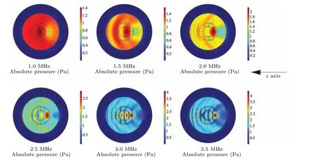
Fig.11.Sound field distribution of PVC–water–PVC–water multiple-layered spherical structure with four-layer of 1:3:1:5 incident by unidirectional monochromatic wave.The frequency points are 1.0 MHz,1.5 MHz,2.0 MHz,2.5 MHz,3.0 MHz,and 3.5 MHz respectively.
4.Conclusion
This paper proposes a prediction of negative ARF based on a multiple-layered spherical structure.The ARF of the multiple-layered spherical structure is calculated and deduced,and the analytical solution is obtained.The physical mechanism of the negative acoustic radiation produced by multiplelayered spherical structure is described.This result is verified by finite element numerical simulations.This design concept is of great significance to the design of real “acoustic tweezers” based on negative ARF and lays a foundation for the design of devices producing negative ARF.This work proves that it is feasible to suppress backscattering to make the structure subject to negative ARF.In the process of designing a multi-layer structure to achieve negative ARF, we should try to choose a structural design that can significantly suppress backscattering, which is also the conjecture proposed by Marston before.[38]In order to better realize this effect, we think that there should be a multiple-layered structure.Through numerical verification,the four-layered spherical structures with specific ratio could have a strong suppression effect on backscattering, thus exhibiting the anomalous characteristic of being subjected to negative acoustic radiation force.The different proportions of the thickness of the fourlayered structure could form different resonant cavities,which can effectively adjust the scattering sound field of the structure, thereby achieving the suppression of backscattering.In the work, these specific scaling parameters are chosen as a result of extensive numerical calculations.In most of the parametric results,the inversion of the ARF does not appear.Further, based on the same mechanism, other structural designs are expected to be proposed.This work has broad application prospects in the fields of medicine, life science, underwater manipulation,and so on.
Appendix A
MatrixA1Nand matrixA2Nare expressed in Figs.A1 and A2.
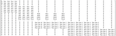
Fig.A1.Matrix A1N.
Here, for the boundary from the external medium to the first layer:
For the boundary from the first layer to the second layer:
For the boundary from theq-th to theq+1-th layer which is not the innermost layer
For the boundary from theq-th to theq+1-th layer which is the innermost layer
General term parameters:
where,cq+1,1is the longitudinal wave velocity of theq-th layer structure,cq+1,2is the shear wave velocity of theq-th layer structure.γq+1,1is the longitudinal wave absorption coefficient of theq-th layer medium,γq+1,2is the longitudinal wave absorption coefficient of theq-th layer medium.µq+1andλq+1are the density coefficients of theq-th layer.
Acknowledgements
Project supported by the National Key Research and Development Program of China(Grant No.2020YFA0211400),the State Key Program of the National Natural Science Foundation of China (Grant No.11834008), the National Natural Science Foundation of China (Grant Nos.12174192 and 12204119), the Fund from the State Key Laboratory of Acoustics, Chinese Academy of Sciences (Grant No.SKLA202210),the Fund from the Key Laboratory of Underwater Acoustic Environment, Chinese Academy of Sciences (Grant No.SSHJ-KFKT-1701), and the Science and Technology Foundation of Guizhou Province, China (Grant No.ZK[2023]249).
猜你喜欢
杂志排行

Chinese Physics B的其它文章
- Photophysics of metal-organic frameworks: A brief overview
- Anelasticity to plasticity transition in a model two-dimensional amorphous solid
- Ab initio nonadiabatic molecular dynamics study on spin–orbit coupling induced spin dynamics in ferromagnetic metals
- Ultrafast dynamics in photo-excited Mott insulator Sr3Ir2O7 at high pressure
- Universal basis underlying temperature,pressure and size induced dynamical evolution in metallic glass-forming liquids
- Valley filtering and valley-polarized collective modes in bulk graphene monolayers