A Review of Isolated Bidirectional DC-DC Converters for Data Centers*
2024-01-16Zhang
,*,., n Zhang
(1.School of Automation,Guangdong University of Technology,Guangzhou 510600,China;2.School of Engineering,Deakin University,Melbourne 3125,Australia;3.Global Data Services Holdings Ltd.,Guangzhou 510600,China)
Abstract: In today’s fast-paced,information-driven world,data centers can offer high-speed,intricate capabilities on a larger scale owing to the ever-growing demand for networks and information systems.Because data centers process and transmit information,stability and reliability are important.Data center power supply architectures rely heavily on isolated bidirectional DC-DC converters to ensure safety and stability.For the smooth operation of a data center,the power supply must be reliable and uninterrupted.In this study,we summarize the basic principle,topology,switch conversion strategy,and control technology of the existing isolated bidirectional DC-DC converters.Subsequently,existing research results and problems with isolated bidirectional DC-DC converters are reviewed.Finally,future trends in the development of isolated bidirectional DC-DC converters for data centers are presented,which offer valuable insights for solving engineering obstacles and future research directions in the field.
Keywords: Data centers,isolated bidirectional DC-DC converters,power electronics topology,control strategy
1 Introduction
Data has contributed to the evolution of humanity,and technological advances driven by big data have produced substantial benefits for society.The emergence of next-generation information technology has resulted in significant changes in our production and development[1].The demand for Internet products and services is rapidly growing,and traditional data-processing scales are falling short of satisfying current application requirements.Data centers play a crucial role in transmitting large amounts of data.Their construction is experiencing robust growth and occupying an increasingly prominent and vital position[2-3].
With the expansion and enhanced capabilities of data centers,several challenges have arisen,such as ensuring reliable operation,effectively managing substantial energy consumption,and dealing with the costs associated with maintenance and management[4].
Traditional data centers focus on application stability,data security,and reliability,whereas less attention is paid to resource utilization,energy savings,and efficiency.The development of data centers focuses on the dynamic deployment of resources,improved resource utilization,reduced energy consumption,and green environmental protection.Since the concept of distributed generation was introduced in China in the 1990s,it has gained increasing attention owing to its reliable power supply,minimal transmission loss,suitability for renewable energy applications,and bidirectional distribution capabilities.Distributed generation has become an important development goal in the construction of smart grids and the energy Internet.Therefore,a distributed power generation system should be established to provide energy to a data center to ensure the stability of its power supply,alleviate the power supply pressure on the distribution network,and achieve the efficient use of green energy[5].
However,all forms of distributed generation and energy storage must be connected to the grid through a power conversion system.Development of adaptable DC distribution networks and micro-grids,various high-and low-voltage distribution buses require power-conversion systems.Therefore,the traditional distribution networks,mainly composed of transformers and switches,will change in the future.Power conversion systems will play a prominent role,not only in achieving a variety of AC and DC voltage conversions and voltage level conversions,but also in enabling flexible control and intelligent management of power flow.This will help to establish an energy conversion network connecting AC/DC transmission and distribution networks,distributed generation,energy storage,and loads[6].In the current range of power conversion systems,the drawbacks of power-frequency isolation transformers,such as their bulky size,heavy weight,and excessive noise has impeded their widespread adoption.In recent years,high-frequency isolation transformers have replaced traditional power-frequency isolation transformers owing to their advantages of small size,light weight,low cost and the ability to significantly improve the power density of a power conversion system.An isolated bidirectional DC-DC converter is the key to a high frequency isolated power-conversion system.An isolated bidirectional DC-DC converter can adjust the voltage turn ratio by changing the voltage ratio between the primary and secondary windings of a transformer.This offers excellent electrical isolation,making it ideal for applications that require high safety standards and have significant differences in the input and output voltage levels.Distributed power supply systems based on isolated bidirectional DC-DC converters have become a requirement for the construction of future data centers with higher precision,concentration,and reliability[7].
The remainder of this paper is organized as follows:Section 2 introduces the topologies and control strategies of isolated bidirectional DC-DC converters.Section 3 discusses the energy consumption and power supply framework of data centers.Subsequently,existing research results and problems with isolated bidirectional DC-DC converters are reviewed in Sections 4 and 5.Finally,conclusions and future work are presented in Section 6.
2 The topology and control strategy of isolated bidirectional DC-DC converters
An isolated bidirectional DC-DC converter converts DC voltage to an AC voltage waveform on the primary side of the transformer.The AC voltage waveform passes through a high-frequency transformer and is rectified into a DC waveform on the secondary side.The converter can achieve a high voltage gain under the premise of electrical isolation,which is a good choice for electric vehicles,energy storage systems,data centers and other fields.The topology classification and control strategy of isolated bidirectional DC-DC converters are summarized as follows.
2.1 Topology
A comparison of various topologies of isolated bidirectional DC-DC converters is presented in Tab.1.
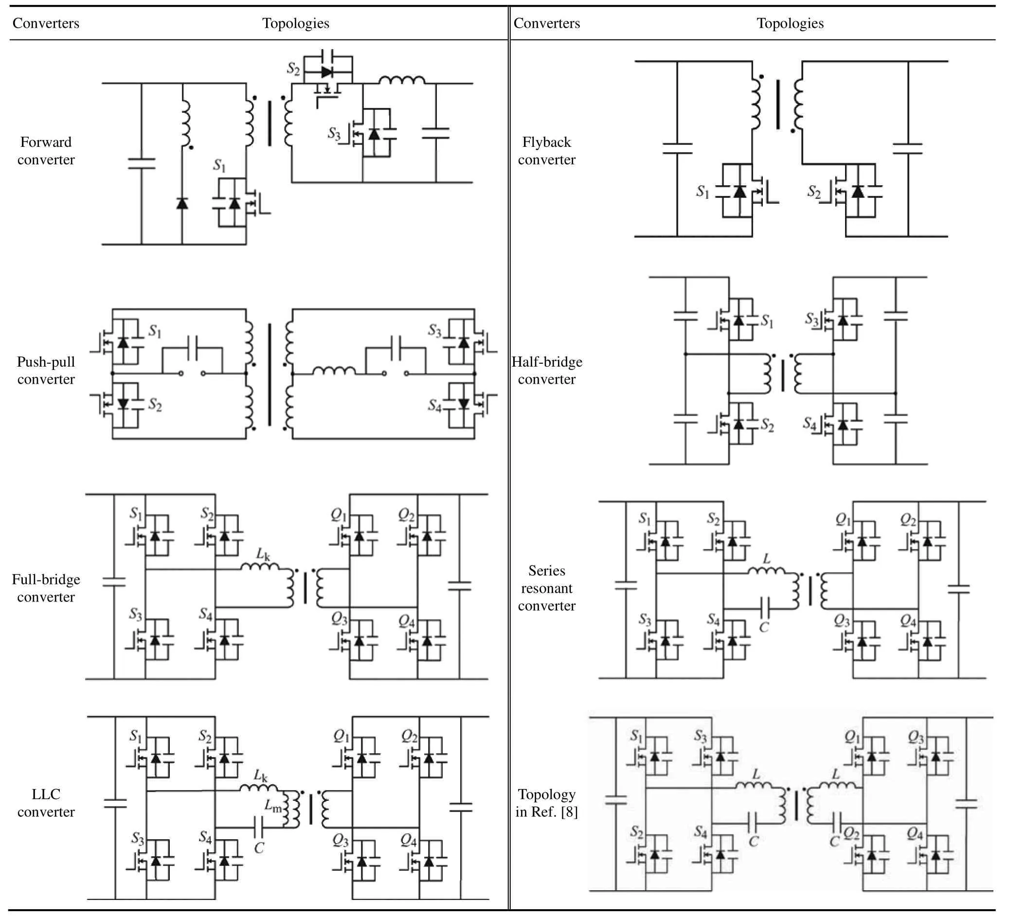
Tab.1 Comparison of various topologies of isolated bidirectional DC-DC converters
2.1.1 Bidirectional forward converters
A bidirectional forward converter can operate in the forward,reverse,and alternate transmission modes.SwitchesS1andS2are turned on and off simultaneously and work complementarily withS3.The bidirectional forward converter has a simple circuit structure,and the drive circuit is easy to design;however,the transformer is in a unidirectional excitation state,and the utilization rate is low.
2.1.2 Bidirectional flyback converters
SwitchesS1andS2in the bidirectional flyback converters are driven alternately in a complementary manner.When the converter is operating in the forward direction,S1is turned on,andS2is always on.An anti-parallel diode was used for continuous flow,and the energy was stored on the primary side of the transformer.When the converter operates in the reverse direction,the working states ofS1andS2are opposite to those in the forward direction,and energy is transferred to the output side.The leakage inductance of the transformer and the parasitic capacitance of the switches invert the potential resonance phenomenon,causing voltage spikes and ringing problems.
2.1.3 Bidirectional push-pull converters
When the bidirectional push-pull converter operates in the forward direction,S1andS2are simultaneously switched on by pulse width modulation,whereasS3andS4are turned off,and their anti-parallel diodes are used for continuous flow.When the converter operates in the reverse direction,S3andS4are turned on,whereasS1andS2are turned off.However,transformer leakage results in high voltages and currents stress on the switches,making them unsuitable for high-voltage applications under harsh environmental conditions.
2.1.4 Half-bridge converters
Both sides of the converter have a voltage-fed half-bridge structure.The advantages of a simple topology and fewer components make it suitable for small-and medium-power applications.The directions of power and energy transmission can be adjusted by controlling the phase shift angle between the primary and secondary switches,and a zero-voltage switch (ZVS) of all switches can be achieved.Because the power transmission of the bidirectional converter is directly proportional to the number of switches used,it results in twice the voltage and current stress on the switches,compared to the full-bridge structure.This can damage the switches and is considered unsuitable for high-power applications.
2.1.5 Full-bridge converters
In recent years,dual active bridge converters (DAB)have become the most widely used bidirectional DC-DC converters.A voltage-fed full-bridge structure is used on both sides of the DAB.The phase-shift control method was used to change the direction and magnitude of the energy transfer by adjusting the phase-shift angle between the primary and secondary switches.When the DAB operates in the forward direction,the driving waveform of the primary switch precedes that of the secondary switch.When operating in the reverse direction,the driving waveforms of the primary switches were behind those of the secondary switches.DAB switches bear less voltage and current stress and are most suitable for high-voltage and high-power applications.In addition,it is easy for all switches to achieve zero-voltage turn-on,which reduces the conduction loss of the switch.
Although DAB has many advantages,it also has drawbacks.Because the DAB uses the voltage difference generated at both ends of the inductorLkto transmit energy,the energy transmitted from the primary side to the secondary side cannot be fully output,resulting in a circulating current in the converter.In addition,DAB has a large turn-off loss and cannot achieve soft switching in all voltage-gain ranges.
2.1.6 Resonant converters
Owing to the problems of circulating current loss and narrow soft-switching range of bidirectional full-bridge converters,resonant converters have been proposed.Resonant converter switches can realize the advantages of the ZVS and ZCS simultaneously,and their power conversion efficiency is the highest in the existing isolated DC-DC converter topology.
Typical topologies of resonant circuits are series and LLC resonant converters.The topology of the series resonant converter is based on the DAB,which add additional resonant capacitors and inductors to form a resonant network.However,for a resonant network consisting of two resonant elements,the maximum output voltage gain of the series resonant converter is one;it can only work in the step-down mode;therefore,it is unsuitable for applications with a wide range of voltage gains.
The LLC resonant converter is based on the series resonant converter and adds an excitation inductance to form a new resonant network.The primary-side soft-switching characteristics of the converter are associated with the excitation inductance.In contrast to the series resonant converter,it is easier to achieve ZVS,which can operate in step-up or step-down modes,with a wider range of applications.Nevertheless,the efficiency of the LLC resonant converter is influenced by its high switching frequency and wide voltage gain range.In addition,the voltage gain range is limited when operating in reverse mode.A bidirectional CLLC resonant converter was proposed in Ref.[8].Compared with the LLC resonant converter,a set of LC networks is added to the secondary side of the transformer,resulting in a circuit topology that is completely symmetrical during both the forward and reverse operations of the converter.In the case of high efficiency,the voltage gain range is extended and the control difficulty of the converter is reduced.The characteristics(advantages,disadvantages,and applications) of a typical isolated bidirectional DC-DC converter are listed in Tab.2.
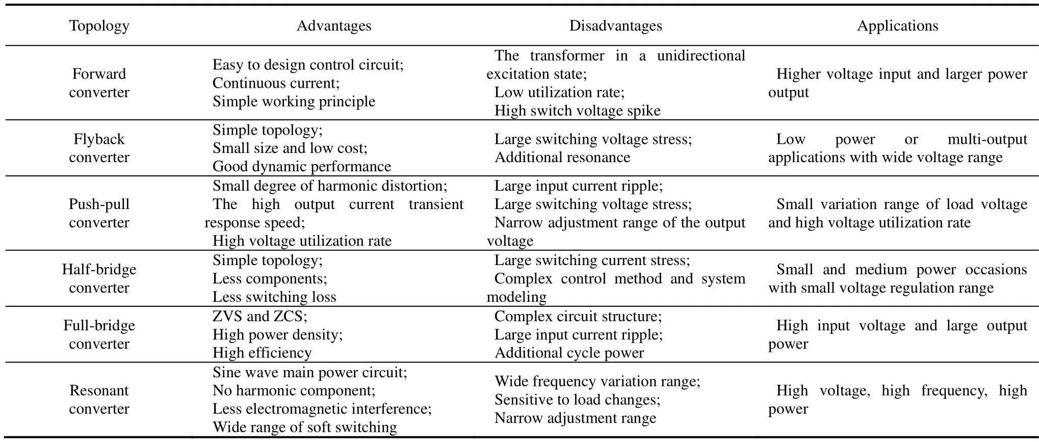
Tab.2 Characteristics of typical isolated bidirectional DC-DC converters
2.2 Switch conversion strategy
The application of the switch conversion strategy in isolated bidirectional DC-DC converters is mainly reflected in the control of the alternating conduction of bridge arm switches in a dual active bridge topology.
2.2.1 Single-phase shift (SPS) modulation
Single-phase shift (SPS) modulation has been widely used as the most classical modulation method in DC-DC converters[9].In SPS,the diagonal switches are turned on simultaneously,whereas the no diagonal switches are switched in turn,ensuring a 180° phase difference between each switch.This generates a square-wave AC voltage on both the primary and secondary sides of the transformer.Therefore,a phase shift occurred only between the primary and secondary sides of the transformer.Modifying the magnitude and orientation of phase-shift angleDcan change the amplitude and flow direction of the transmission power of the converter and its associated steady-state behavior.A waveform diagram of SPS is shown in Fig.1.

Fig.1 Waveform diagram of SPS
SPS is essentially a control algorithm with active power as the core and less flexibility in power regulation.Only one duty cycle was considered when the switch was driven.The converter can only achieve a lower mean-square root current,smaller current stress,wider soft-switching range,and higher transmission efficiency when the output and input voltages match.When the input and output voltages do not match,the power flow and current load of the converter significantly increase.This can increase the loss of power devices and magnetic components and reduce the converter efficiency[10].To improve the defects of SPS,new shift concepts,such as EPS,DPS,and TPS have been proposed.The conversion efficiency of converters can be improved by increasing the number of phase-shift angles and changing the relationship between them.
2.2.2 Extended-phase shift (EPS) modulation
As a typical improvement of the SPS modulation strategy,the EPS modulation strategy differs from the SPS modulation strategy by setting an external phase-shift angleDE1on both the primary and secondary sides of the transformer and an additional internal phase-shift angleDE2on either the primary or secondary side[11].Therefore,in the EPS modulation strategy,one side of the transformer outputs a three-level AC voltage,whereas the other side outputs a two-level AC voltage with a duty cycle of 50%,similar to the SPS.A waveform diagram of the EPS is shown in Fig.2.
Compared with SPS modulation,EPS can not only improve the transmission efficiency,but also expand the operating range of ZVS,reduce the current stress and decrease the reactive power[12-14].In EPS,the external phase-shift angle is utilized to control the magnitude and flow direction of the power transmission,whereas the internal phase-shift angle is manipulated to optimize the steady-state performance of the converter.When the converter switches between boost and buck modes or the power transmission direction changes,the internal phase-shift angle shifts to the other side to maintain the consistency of the forward and reverse operations of the converter.
2.2.3 Double-phase shift (DPS) modulation
Double-phase shift (DPS) modulation was proposed in Ref.[15].This is similar to EPS modulation except for the phase-shift angleDD1between the primary and secondary sides of the transformer.A waveform diagram of the DPS is shown in Fig.3.Phase-shift angleDD2exists between the primary and secondary sides of the full bridge.By adjusting the phase-shift angles,the backflow power and voltage stress of the converter can be reduced while ensuring the output power,thereby reducing the loss and improving the efficiency of the system.In Ref.[16],the working principle of the DPS and the converter were introduced and analyzed in detail.Mathematical models of the transmission and backflow power were established,and the control performances of the DPS and SPS were compared.Under the same power transmission conditions,DPS modulation reduces the power flow of the converter and improves the flexibility of power regulation[17-19].
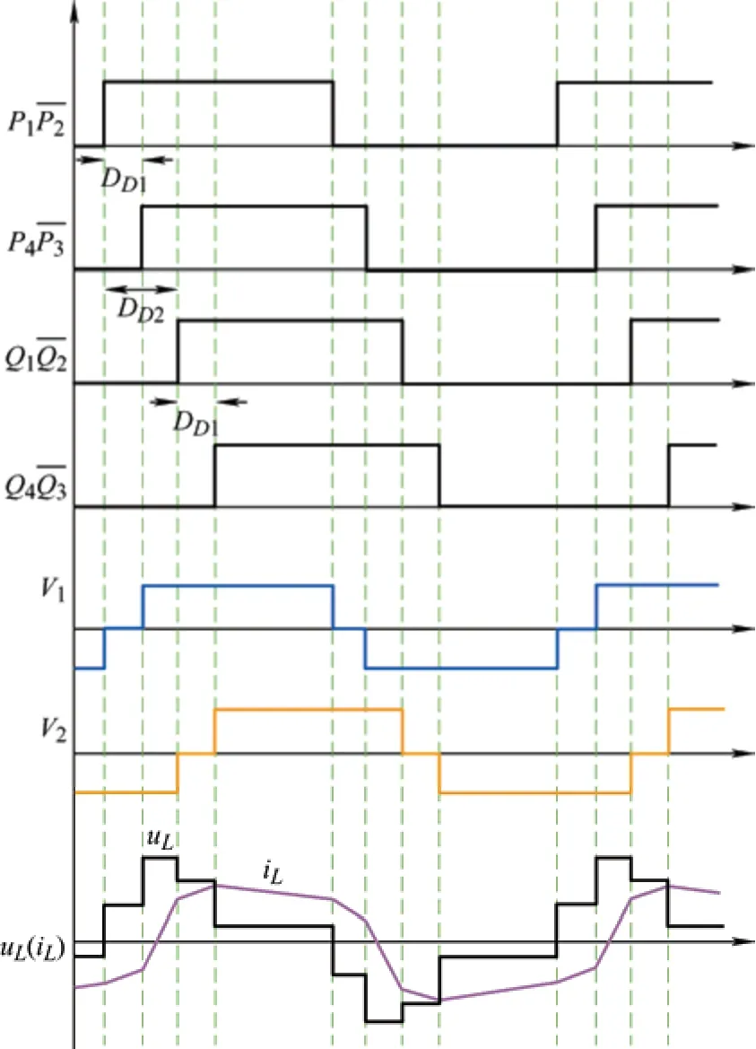
Fig.3 Waveform diagram of DPS
2.2.4 Triple-phase shift (TPS) modulation
TPS modulation consists of external phase-shift angleD3and two independently controllable internal phase-shift anglesD1andD2,located on the primary and secondary sides,respectively.A waveform diagram of the TPS is shown in Fig.4.Therefore,the TPS contains three optimal control quantities that can be controlled separately[20].Among the three modulation strategies of SPS,EPS,and DPS,it has the greatest potential for performance optimization.The optimal TPS modulation design for soft switching,transmission power,and current stress is discussed in Refs.[21-23].Compared with the other three modulation strategies,TPS enables the bidirectional converter to achieve minimum current stress,minimum root-mean-square current,minimum power loss,and maximum ZVS range.

Fig.4 Waveform diagram of TPS
SPS,EPS,and DPS modulation can be regarded as special cases of TPS modulation.WhenD1=D2=1,TPS modulation can be considered as SPS modulation.WhenD1=1 orD2=1,TPS modulation can be considered as EPS modulation.WhenD1=D2,the TPS modulation can be considered as DPS modulation.A relationship diagram for the four modulation methods is shown in Fig.5.

Fig.5 Relationship between the four modulation methods
2.2.5 Modified frequency modulation
In addition to the phase shift modulation strategy,the modified frequency modulation strategy has become a commonly used optimal modulation method for bidirectional DC-DC converters.Because a high switching frequency can result in increased system loss,a lower switching frequency may enhance both efficiency and power transfer in the event of wide-range transmission power.Modified frequency modulation is commonly combined with phase-shift modulation for converter optimization.A new modified frequency-phase-shift modulation method was proposed by Hiltunen[24]to reduce the reactive power of the DAB DC-DC converter,while expanding the ZVS range.In Ref.[25],frequency conversion modulation was combined with TPS modulation to obtain four optimized degrees of freedom to achieve the minimum effective inductor current value in the entire power range and improve the efficiency under heavy loads.Frequency conversion-phase shift modulation can further improve the transmission efficiency and steady-state performance of the converter,but this complex modulation strategy places higher requirements on solution technology.
2.3 Control strategies
2.3.1 Proportional-integral-derivative control
Proportional-integral-derivative (PID) control is one of the earliest developed control strategies.That is widely used in industrial process control owing to its simple algorithm,high robustness,and high reliability.Currently,approximately about 90% of control loops in industrial applications still have a PID structure.Briefly,a control error was generated based on the set and measured output values.Based on the relationship between the proportional,integral,and differential calculations,the error was employed as the controlling parameter for the system.This can also be optimized using basic PID control[26].However,conventional PID controllers have certain limitations.As a linear controller,it is often characterized by inadequate tuning and insufficient performance for complex systems with nonlinear,time-varying uncertainties and strong interference.The overall structure of the PID controller is illustrated in Fig.6.

Fig.6 Overall structure of a PID controller
2.3.2 Sliding mode control
Nonlinear elements exist in the topology of the isolated bidirectional DC-DC converter,which makes the dynamic equation of the converter nonlinear.Therefore,it is preferable to use a nonlinear control strategy to obtain an accurate model of the system that considers the disturbances.
Sliding mode control,also known as variable structure control,is a special type of nonlinear control with a control discontinuity.In the dynamic process,the system is continuously transformed according to the current state of the system (such as deviation and derivatives),forcing it to move according to the state trajectory of a predetermined sliding mode.The overall structure of the sliding mode controller is shown in Fig.7.When a large signal appears in the bidirectional converter,an external disturbance is generated,whereas a minor signal analysis based on the state-space averaging model cannot predict the behavior of the regulator.The finite-time convergence of sliding mode control and its low sensitivity to external disturbances make it a suitable control strategy for overcoming this condition.A sliding-mode control strategy based on the average output current model of a DAB converter was proposed in Ref.[27].Because there is no integral control,the converter has a current spike and a steady-state error.Thus,single-integral sliding mode control is applied to a single DC-DC converter in Ref.[28].However,the single-integral effect was insufficient.To solve this problem,a double integrator was added to the single integral sliding mode surface.An output voltage and current regulation strategy based on a double-integral sliding mode control was proposed in Ref.[29].A nonlinear state space-model of the DAB converter output voltage and current regulation was established.The double-integral sliding mode controller offers not only a zero steady-state error,but also a fast transient response in the face of load changes.In addition,it exhibits strong robustness to model uncertainties and disturbances.
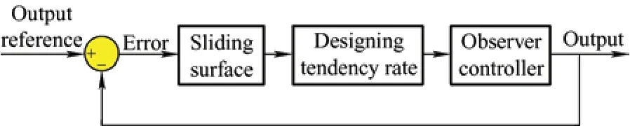
Fig.7 Overall structure of a sliding mode controller
2.3.3 Fuzzy controll
Fuzzy control is an intelligent control method based on fuzzy set theory,fuzzy linguistic variables,and fuzzy logic reasoning that mimics human fuzzy reasoning and decision-making processes based on behavior.This approach initially translates the knowledge of an operator or expert into a set of fuzzy rules.Subsequently,the real-time signal obtained from the sensor is fuzzified and applied as an input to a fuzzy rules.The system then performs a fuzzy inference and generates an output value that is added to the actuator.For imprecise nonlinear systems with uncertainties,parameter fluctuations,and load fluctuations,fuzzy control is an effective approach for achieving robust response characteristics.The overall structure of the fuzzy controller is illustrated in Fig.8.
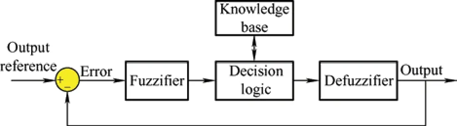
Fig.8 Overall structure of a fuzzy controller
A direct power control method for a DAB converter based on fuzzy logic was proposed in Ref.[30] to improve the output voltage regulation and fast transient response during load changes.The voltage error signal and error integral were used as language inputs for the fuzzy controller to generate the power reference.Subsequently,the phase shift corresponding to the given power reference was calculated to control the power flow.In Ref.[31],a fuzzy logic controller was designed for a photovoltaic lighting system to ensure fast dynamic response.Owing to their inherent adaptability and robustness,charge and discharge current can be modified in response to alterations in the parameters.A controller based on fuzzy logic is easy to design and implement.This requires only minimal mathematical modeling and obviates the requirement for linearization assumptions,thereby circumventing a convoluted design.
2.3.4 Boundary control
Boundary control,which is essentially a geometric control method,is suitable for switching converters with time-varying circuit topologies.This uses the state-space plane to analyze the switching converter’s large-signal characteristics and establish an appropriate control strategy,thus,addressing the converter’s complete operational problem holistically without distinguishing the start-up,transient,and steady-state modes.Based on a study of the converter trajectory in the phase plane,a switching surface was defined to indicate the switching action without linearizing the system.
A design technology for a self-oscillating DC-DC converter with boundary control was proposed in Ref.[32].A detailed study was conducted on the modeling and analysis of state trajectory motion for first-order switched-surface converters,providing excellent signal response and stability but lacking transient response to disturbances.Therefore,a second-order switching surface was proposed[33],that was obtained by estimating the state trajectory motion after the switching action,thereby accelerating the velocity of the trajectory motion along the switching surface.Compared with the boundary control of the first order switching surface,the converter is quickly restored to a steady state through two switching actions under large signal interference,showing better dynamic characteristics.Many boundary control studies are limited to the converter’s continuous conduction mode (CCM);however,additional limits are inevitably generated owing to the zero-inductance current when the converter operates in the discontinuous conduction mode (DCM).A buck converter suitable for the DCM mode,designed for the comparison of first-and second-order switch surface boundary controls,was proposed in Ref.[34].By analyzing the average output voltage,output ripple voltage and large signal characteristics,it was verified that the designed second-order switching-surface boundary controller was suitable for both CCM and DCM modes,making the voltage drift absent when the converter operated in the DCM mode.
2.3.5 Model predictive control
Model predictive control (MPC) uses a dynamic process model and a predefined cost function to enable system variables to follow their reference values.Model prediction consists of four basic components:prediction model,feedback correction,rolling optimization,and reference trajectory.First,a model describing the dynamic behavior of the system is used to predict the future value of the process output according to the control input of the system and the historical information of the process.Second,the predicted value of the model is corrected by comparing the measured output value with the predicted value of the model.Subsequently,a specific performance metric was optimized to determine the effectiveness of future control.To ensure a gradual transition for both the input and output,the process output must approach the set value smoothly along a reference path.The overall structure of the model predictive controller is shown in Fig.9.
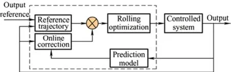
Fig.9 Overall structure of a model predictive controller
Model predictive control is divided into two categories: finite control set-model predictive control(FCS-MPC) and continuous control set model predictive control (CCS-MPC).The concept of FCS-MPC was first proposed in Ref.[35] and applied to three-phase voltage-source inverters.The model-predictive control method with a finite control set was compared with PI control in Ref.[36],demonstrating the superiority of the FCS-MPC control.When the FCS-MPC is applied to power electronics,the state of the switch tube in a switching cycle is simplified to be normally open or closed.Thus,the control signal is expressed as a binary signal,that is“0” and “1”.Owing to its ability to perform real-time prediction of variables,such as current,voltage,and flux linkage,FCS-MPC is suitable for various control scenarios.
A continuous control-set explicit MPC method based on the average model of a boost converter was proposed in Ref.[37].A photovoltaic maximum power point tracking (MPPT) scheme based on continuous control set-model predictive control was proposed in Ref.[38].The small-signal model of the photovoltaic system was adaptively obtained using online optimization of the cost function to satisfy the performance of transient and interference suppression.FCS-MPC enables the selection and application of its switching state to have a low computational load and a fast operation speed.However,CCS-MPC requires additional modulation to obtain the control signal,resulting in a more complex control process.
2.3.6 Optimization based on a meta-heuristic algorithm A metaheuristic algorithm can search globally to a certain extent and find an approximate optimal solution.This does not rely on the organizational structure information of the algorithm;hence,it is suitable for function combination optimization and calculation.Currently,genetic algorithms (GAs) and particle swarm optimization (PSO) algorithm have become the most commonly used meta-heuristic algorithms for the efficiency optimization of isolated bidirectional DC-DC converters,with the advantages of solving complex problems and better global optimization performance.
(1) Genetic algorithm.A GA is a type of search algorithm that simulates the mechanism of biological genetics and natural selection.It is constructed by artificial means to operate the coding of parameters rather than the parameters.Therefore,the GA has the advantages of strong global search capability,good stability,fast convergence speed and easy expansion,ensuring that it is suitable for calculating large-scale complex system models.A multiobjective efficiency optimization scheme based on a GA and TPS modulation was proposed in Ref.[39].The optimization scheme includes three objectives:reducing the root-mean-square root current,decreasing the current stress,and achieving ZVS performance.The multi-objective optimization challenge was effectively addressed,resulting in an optimized modulation strategy that significantly minimized the conduction,switching,and magnetic component losses of the DAB DC-DC converter.An optimized modulation strategy based on a GA for a novel resonant isolated bidirectional converter was proposed in Ref.[40],which reduced the reactive power of the system,improved the total harmonic distortion,and extended the soft-switching range.However,GAs also have certain limitations,including excessive reliance on parameters and inadequate local search capabilities,which limit further enhancements in their optimization potential.
(2) PSO algorithm.PSO is based on the study of bird predation behavior by simulating the behavior of birds flying and foraging to achieve the optimal goal.PSO does not have crossover and mutation operations in the genetic algorithm,but follows the current known optimal value to find the global optimal solution,resulting in few parameters to be adjusted,fast convergence speed,and easy implementation.A unified harmonic analysis model reactive power-optimization modulation strategy based on TPS and PSO proposed in Ref.[41] is used to determine the phase-shift angle of the minimum reactive power.A hybrid five-variable optimization modulation strategy based on the PSO algorithm was proposed in Ref.[42].This strategy includes phase-shift modulation and pulse-width modulation (PWM),effectively reducing the root-mean-square current of the converters.An EPS strategy based on GA and PSO algorithms to optimize the reflux power of a DAB DC-DC converter was proposed in Ref.[43].PSO also has some limitations,such as a lack of dynamic speed adjustment,ease of falling into local optimization,low convergence progress and convergence difficulties.The advantages and disadvantages of the various control technologies are listed in Tab.3.

Tab.3 Advantages and disadvantages of various control technologies
3 Features of data center applications
3.1 Energy consumption
Data centers are infrastructures for digital transformation and development,which support people’s daily lives and maintain the normal operation of society.With the global decarburization trend,the“green” transformation and development of data centers has become an important part[44].
It is estimated that in 2020,97% of the global network traffic will be related to data centers.
However,as information infrastructures,data centers consume a large amount of energy.A typical data center consumes energy equivalent to that of 25 000 households,which is 100-200 times greater than a comparably sized standard office[45].In 2005,the energy usage of data centers in the United States alone represented 1% of the nation’s entire electricity consumption,and the ensuing carbon emissions were commensurate with those produced by medium-sized nations such as Argentina.In 2010,data center electricity consumption constituted 1.1%-1.5% of the world’s total electricity consumption,with America’s domestic data center energy consumption comprising 1.7%-2.2% of the nation’s total electricity usage.Data centers are set to become the world’s largest energy-consuming entity,with the proportion of energy consumed estimated to increase from 3% in 2017 to 4.5% in 2025[46].
Power utilization efficiency (PUE),first proposed in 2006[47],was used to measure the ratio of total data center power consumption to IT equipment load power consumption.This is an important indicator of the energy efficiency of data centers.The closer the PUE value is to one,the less power is consumed by non-IT devices,such as refrigeration and lighting,and the higher the energy efficiency of the data center.The energy consumption of a data center can be divided into four main components: IT equipment loss (50%),refrigeration equipment loss (37%),distribution system loss (10%),and auxiliary lighting loss (3%)[46].The power consumption ratios of various devices in the data center are shown in Fig.10.Remarkably,the energy consumption of refrigeration systems exceeds one-third of the total energy consumption of a data center.Currently,the average PUE value of large data centers in China is 1.55,and the average PUE value of super-large data centers is only 1.46.The Ministry of Industry and Information Technology of China,explicitly outlines the PUE standards for data centers in the “Three-Year Action Plan for the Development of New Data Centers (2021—2023)”: by the end of 2021,the PUE for new,large and above data centers should be less than 1.35,and by 2023,this number should drop to below 1.3.

Fig.10 Power consumption ratios of various devices
Combined with the background of “carbon peak and carbon neutrality”,green energy-saving development,elimination of high-energy-consuming components and improvement of resource utilization are the indisputable development trends of data centers.
3.2 Power supply framework
A reasonable selection of the power supply architecture of data centers can reduce the energy consumption of the entire system and improve the utilization rate of resources.The UPS was originally applied to the power supply system of a data center.With the increasing demand for data centers,new power supply modes have emerged,such as distributed lithium power DPS,low-voltage DC,and high-voltage DC.
3.2.1 Traditional AC uninterrupted power supply
Currently,the traditional AC UPS power supply system is the most widely used in data centers,consisting of an input-side rectifier,an output-side inverter,and a DC bus connected to the battery.The architecture of the UPS is illustrated in Fig.11.When the grid is normally connected,the load is powered by a rectifier and an inverter,and the battery floats simultaneously.When the grid is interrupted,the battery transitions from a floating charge to a discharge state,and the inverter delivers AC power to ensure reliable power regulation and backup support for continuous data center operations.
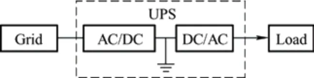
Fig.11 UPS system architecture
Owing to the incidental single point failure caused by the structural load of UPS equipment,there are redundant power supply architectures such as the N single operation system,N+X parallel redundant system,2N dual operation system,and “grid +U power” to improve the reliability and uninterrupted operation of UPS equipment[48].However,the traditional AC UPS power supply system has low power conversion efficiency after multiple conversions between the rectifier and inverter,resulting in a high harmonic current-distortion rate.
3.2.2 Distributed lithium power supply
With the increasing demand for services,the traditional UPS system,which has a very low utilization rate and considerable power consumption,cannot adhere to the requirements of green energy savings and high efficiency.Therefore,considering the efficiency of the equipment,a new distributed lithium power supply (DPS) is proposed.The architecture of the DPS system is shown in Fig.12.A data center employs a distributed power supply (DPS) system to ensure that backup power is available for each individual rack with a lithium iron phosphate battery pack serving as direct backup power for the servers[49-50].Under normal circumstances,the DPS enters the charging state when the grid is connected and turns to the battery state with the backup battery starting to work when the grid is interrupted,ensuring a 240 V high-voltage DC power output to the server.

Fig.12 DPS system architecture
Distributed power-supply technology divides the centralized power supply and distribution system into parts,thereby decreasing the energy consumption,size and weight of the data center power supply system.In addition,it improves the reliability and space utilization of power-supply systems.However,compared with a large centralized UPS system,multiple distributed minicomputer systems have more fault points and higher initial investment costs.In addition,the characteristics of each battery in the battery pack as a backup serving power supply cannot be guaranteed to be completely consistent when producing an unstable power supply,thereby reducing the efficiency of the energy transmission[51].
3.2.3 Low-voltage DC (LVDC) power supply
A 48 V power supply architecture is commonly used in the communications industry and is currently used in the data center industry[52].The LVDC power supply system can directly provide power to the DC load equipment in data centers,and the battery is used as a filter to avoid external interference,interference from high-frequency switching operating voltage,transient overvoltage change,lightning overvoltage,and harmonics in the AC power supply for communication.In addition,low-voltage buses are safer and less difficult to maintain.The low-voltage DC power supply architecture is shown in Fig.13.
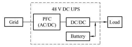
Fig.13 Low-voltage DC power supply architecture
However,low-voltage DC power-supply systems have certain limitations.Because of the low bus voltage level,the DC load current increases exponentially,generating a corresponding increase in the required cable cross-sectional area,thereby increasing the conduction loss and construction costs.With the substantial demand for power in data centers,the widespread implementation of low-voltage DC power is challenging.
3.2.4 High-voltage DC (HVDC) power supply
The 380 V high-voltage direct current technology has been used for many years at home and abroad.The high-voltage DC power supply architecture is shown in Fig.14.The traditional 48 V power supply system is unsuitable for large-scale distributed clean energy applications such as solar and wind,owing to its low voltage,high transmission loss,and large cable investment.Relatively speaking,the 380 V high-voltage DC system has great advantages owing to the increasing bus voltage,reduced line conduction loss,and improved energy utilization[53].

Fig.14 High-voltage DC power supply architecture
Compared to the traditional UPS architecture,the HVDC power supply system minimizes AC-DC conversion,reduces the requirement for energy storage components,and reduces the overall size and volume of the system.However,the internal equipment of a data center is complex with different specifications,ranging from the main server to various cooling,lighting,and other non-IT equipment.When all devices have uniform specifications to accommodate 380 V DC power supplies,the cost and complexity of development are major barriers to the widespread implementation of high-voltage DC power systems in data centers.
4 State-of-art applications of bidirectional DC-DC converters for data centers
4.1 High-ratio wide input transition characteristics
The operation states of the isolated bidirectional DC-DC converter directly affect the status of the data center power supply system;however,its role goes far beyond its contribution to stabilize the power supply.The bi-directional flow of energy between the bus bar power supply and energy storage battery,as well as the provision of power to various types and voltage levels of loads,are integral to its critical role.Based on the demand of data centers for quality and efficiency in power conversion,a converter is required to improve efficiency and reduce losses,while ensuring a high voltage ratio and wide input conversion.The isolated bidirectional DC-DC converters with better performance are mainly DAB and LLC resonant converters,which are widely used in data centers.
To satisfy the requirements of high efficiency and low loss in data centers,the focus is on optimizing the stable-state performance of the DAB converter and improving the transmission efficiency from the perspectives of soft switching[54],minimum return power[55-56],minimum current stress[57-58],minimum switching device loss[59],and maximum transmission efficiency[60],to ensure the stability of the data center power supply and power quality.Another focus is on the optimization algorithm selection,and the Lagrange multiplier method is mostly used to establish the Lagrange function of the optimization objective[54,56-58]as shown below.The control quantities of the poles and the phase angles of the optimization target under the constraints were obtained by solving the equations.
whereL(x,y,z)is the constructed Lagrange function,z=f(x,y) is the functional relationship to be solved,and[P(x,y)-P*]=0 is the constraint of the converter at the same transmission powerP*and voltage transmission ration.
In addition to optimizing the steady state characteristics of the DAB,it is also important to optimize its dynamic characteristics.The high-frequency link inductor current of the transient response was added to Refs.[61-62] during unidirectional and bidirectional tidal current changes as a variable in the analysis of the phase shift angle.Therefore,the phase angle of a DAB converter can be adjusted by changing the load or fluctuating the input voltage to achieve a faster dynamic response.The dynamic matrix control algorithm (DMC)[63],sliding mode control[64],boundary control[65],and model predictive control[66]have been applied to control the DAB and improve the dynamic performance of the converter with greater robustness and fast response.
In the application of data centers,it is necessary to reduce the loss caused by fast-switching frequencies and reduce the volume of magnetic components with high-frequency switching devices.A soft-switching bidirectional LLC resonant topology was proposed in Ref.[67].This can not only change the output power and energy flow direction by adjusting the switching frequency but also makes the circuit resonate to achieve soft switching to reduce switching loss.However,the traditional bidirectional LLC resonant converter is clamped by the input voltage at both ends of the transformer excitation inductor in the step-up mode,resulting in an ordinary series LC resonance such that the maximum voltage gain does not exceed one[68].To solve the problem of traditional bidirectional LLC converters,a bidirectional CLLC converter with symmetrical primary and secondary transformer-side structure was proposed in Ref.[69].The CLLC converter has a symmetrical and similar working principle and operating state in the buck-boost mode with no longer limited voltage gain,and zero-voltage switching,and a smaller root-mean-square current can be achieved.Dual-active synchronous (DAS) modulation was adopted for the CLLC converter in Ref.[70] to ensure the stability of bidirectional power flow and reduce the real problem of power loss.Similarly,the dynamic performance optimization of resonant converters is relatively mature.Model predictive control[71],sliding mode control[72]and optimal control[73]have been applied to resonant converters to achieve fast transient response.
4.2 Multiple integrated structure
Owing to the higher requirements of data centers for device volume,weight,power density and other performance and system reliabilities,there has been a focus on optimizing magnetic components for efficiency.The multiple-integrated structure exhibits good performance in reducing the input and output ripples of the system,improving the power level of the converter,and reducing the volume of the magnetic components.Therefore,a magnetically integrated structure to has been proposed to improve the system performance.
The magnetically integrated structure is an integration between the inductor and the transformer.The inductor core described in Ref.[74] is positioned above the transformer core and opposes the magnetic flux within both the transformer and inductor using a typical type-I magnetic strip in transformers.Although the core volume was reduced,this resulted in an overall increase in the height of the magnetic component.However,edge loss caused by the presence of an air gap is challenging to eliminate during high-frequency switching operations.An effective strategy is to reduce the copper content in the zone adjacent to the air gap within the core,thereby mitigating edge losses[75-76].Moreover,the design of an isolated high-output-current DC/DC converter is challenging,owing to the large conduction loss of the transformer windings and the substantial AC termination loss of the connection part with the secondary winding group.The integrated matrix transformer is used to distribute the secondary current of multiple magnetic cores while reducing the leakage inductance to reduce the conduction loss and improve the output current capacity.The primary and secondary windings of the transformer were arranged separately in Ref.[77],and a magnetic shunt was introduced between them to create a path for the magnetic flux leakage,resulting in a greater leakage inductance to replace the requirement for a series resonant inductor.The integrated magnetic structure can eliminate magnetic flux,which helps reduce core size and the core loss[78].Research on high-frequency resonant conversion based on planar magnetics is becoming extensive[79].In Ref.[80],a four-layer PCB was used to implement the matrix transformer function in the LLC converter,integrating the synchronous rectifier and output capacitor as part of the secondary winding group to eliminate the AC short-circuit loss.A new matrix transformer structure was proposed to further improve efficiency and power density[81],which integrates four-component transformers into a magnetic core to minimize the leakage and termination losses and make full use of the available space.The parallel-matrix transformer and inductor proposed in Ref.[82] were integrated into a single-core structure and shared winding,suitable for LLC converters with stable or unstable voltages.Integrated matrix transformers still face challenges with complex structures and multi-core issues;however,there is significant potential to improve their efficiency.
This magnetic integration technology can effectively improve the efficiency and power density of circuits.However,owing to the difficulties in flux control and magnetic design,further efforts are required in the design and optimization of matrix transformers and magnetic integration.
4.3 Modular structure
For data centers,owing to the increasing power levels and high electricity demand,the voltage and capacity levels of a single bidirectional DC-DC converter cannot satisfy the operation of the entire system.As the complexity of the system increases,the conditions for the optimization of the interstructural arrangements also become increasingly harsh.Owing to its ability to increase system power levels and ensure system redundancy,the modular structure is widely regarded as a critical solution for multimodule coordinated control in future data centers.A series modular topology based on a 10 kV SiC-MOSFET half-bridge module was proposed in Ref.[83] for high-current,medium-high-power applications.However,the high rate of change in voltage over time (dv/dt) resulting from the rapid switching of power devices during conversion may adversely affect the service life of the device,requiring the implementation of measures to mitigate the induced current[84-85].Simultaneously,the unbalanced voltage distribution within the phase branch of the series apparatus during the turn-off phase and transitional period must also be considered[86-87].
An important issue in data center applications is the high current level of the low-voltage-side bus,which limits the power level of the resonant converters widely used in data centers to 1 kW or less.Therefore,multiple resonant converters must be connected in parallel to distribute the power stress and increase the current capacity.The problem of sharing parallel structures is an important research topic.An interleaved LCLC converter based on GaN devices was also proposed in Ref.[88].A switch control capacitor (SCC) and resonant capacitor are connected in series to match the impedance of the resonant network.The resonant current in each phase is indicative of the different load levels in different phases,and the series resonant capacitor is adjusted by the SCC to ensure uniform current-sharing across all phases.The current-sharing problem has been thoroughly studied,and various current-sharing methods have been proposed,such as the droop control method[89-90],average current method[91],and master slave control method[92].These methods ensure that data center applications achieve accurate current sharing while maintaining a wide input voltage range and that the interleaved modular structure enables low stress on the output capacitor.
In addition to the research on the isolated bidirectional DC-DC converter connected to the bus when the mains are normally connected,the UPS energy-storage battery is an important part of a data center with indispensable optimization of battery utilization efficiency.In an actual system,the safe operation of the battery pack is affected by factors that cannot be eliminated,owing to differences in the component parameters of the sub-modules and unbalanced conditions between different battery modules.A hybrid-structure voltage equalizer was proposed in Ref.[93],ensuring that power can be directly transmitted from any higher-voltage unit to any lower-voltage unit to achieve a balance between battery pack and the battery unit.A distributed multimode energy-storage battery-control scheme based on a cascaded DAB converter was proposed in Ref.[94].Considering the output voltage limitation and limited voltage gain of the cascaded converter,the circuit is free to switch between three working modes:constant power (constant voltage),constant gain,and power regulation modes by observing the voltage and current inside the module to achieve independent power regulation and output voltage distribution for each sub-module.
5 Future trend of the development of isolated bidirectional DC-DC converters for data centers
Based on the analysis of energy consumption,power supply architecture,and state-of-the-art applications of converters in data centers,it is evident that popular power distribution systems have limitations such as fragmentation,complexity,difficulty in locating faults,low energy efficiency,and insufficient reliability.In addition to the requirements of voltage-level conversion and electrical isolation,an isolated bidirectional DC-DC converter should facilitate bidirectional energy flow switching.This can not only accumulate surplus energy in the energy storage system but also quickly change the direction of power flow whenever there is a power outage.This can provide uninterrupted power supplies for efficient data center performance.For data centers connected to renewable energy source such as solar and wind power,fluctuations in power generation can be unpredictable,leading to uncertain peaks and troughs.At the peak,energy must be fed back into the battery;conversely,at the trough,the battery output helps provide electrical energy to achieve effective energy use.
Simplifying the power supply infrastructure,promoting green energy conservation,and enhancing resource efficiency and power density should be the top priorities in the development of future data centers.The following technologies must be addressed immediately.
5.1 System reliability
Currently,during data center operation,power safety accidents caused by power failure,equipment failure and lightning strike events occur occasionally.Moreover,the loss caused by the power failure of a data center is not only a significant direct economic loss.Maintaining normal continuous operation of a system after a failure is a pressing challenge that every data center must pay attention to.Redundant backup from multiple perspectives is the simplest and most effective method to improve the reliability of data centers.Incorporating a fault-redundancy protection strategy enables for the rapid replacement of a failed unit in the system,ensuring the seamless deployment of a redundant unit and the reliability of the system.Simultaneously,with the development of new power semiconductor devices,innovation and utilization of new power electronic energy change topologies,and advancements in modern control technology,the uninterrupted power supply technology of data centers has significantly improved.This has provided effective technical support for the reliability,configuration adaptability,and scalability of power-supply systems.
5.2 Power density and efficiency optimization
The future development of data centers prioritizes distribution,compactness,and lightness.Isolated DC-DC converters use high-frequency transformers,which are more compact and weightless than the power-frequency transformers previously used in industry.With the promotion and popularization of planar transformers,the power density of these systems can be substantially improved.However,high switching frequencies inevitably lead to switching losses in power devices.Although the loss can be reduced using soft-switching technology,it is still necessary to consider the heat-dissipation problem caused by the loss of circulation,switches,and transformers.In addition,the efficiency of an isolated bidirectional DC-DC converter may not be optimal when the external data center load state changes.A resonant converter can lose some of its soft switching advantages and increase additional losses under light-load conditions.Therefore,a comprehensive consideration of the power level,switching frequency,and dead time is necessary to propose an optimized design scheme for converters under different load conditions.The development of new materials and devices is also important for optimizing data centers.When GaN devices are used instead of Si devices,the power density of data centers can be improved and the power loss can be almost halved,significantly improving the energy efficiency of data centers.
In general,the future development trend is from high voltage/centralized/AC large UPS systems to low voltage/distributed/DC small UPS systems,simultaneously from fossil to “green” energy.In response to the evolving requirements of data services,the development and optimization of data centers requires not only circuit topology and control method optimization,but also the utilization of industrial layouts and wide-bandgap devices in practical engineering applications.Embracing these advancements will propel the progress and enhancement of data centers.The demand and future trends in the development of isolated bidirectional DC-DC converters for data centers are shown in Tab.4.
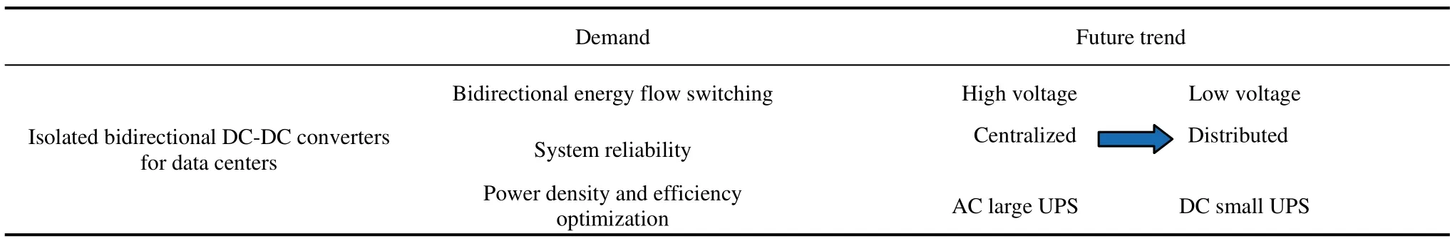
Tab.4 Demand and future trend of the development of isolated bidirectional DC-DC converters for data centers
6 Conclusions
This study comprehensively investigates isolated bidirectional DC-DC converters for data centers.It begins by introducing the development background of data centers and their demand for high-efficiency,high-power-density isolated bidirectional DC-DC converters.Existing topologies and control strategies for isolated bidirectional DC-DC converters are summarized.Furthermore,extensive analyses were conducted on the applications and development trends of isolated bidirectional DC-DC converters for data centers.
The performance of the isolated bidirectional DC-DC converter significantly affects the overall operation of the data centers.While the existing converters satisfy certain operational requirements,practical applications still face challenges such as high-voltage stress on power devices,substantial switching losses,and increased interference.To address these issues,it is suggested that the performance of an isolated bidirectional DC-DC converter must be optimized through innovative topology designs,energy management control,and modularization.This optimization leads to enhanced reliability,power density,and system efficiency in data centers.
杂志排行

Chinese Journal of Electrical Engineering的其它文章
- Comparative Analysis of Vibration and Noise of Axial Flux Motor with Different Pole and Slot Combinations*
- Power Quality Improvement and Signal Conditioning of PV Array and Grid Interfaced Off-board Charger for Electric Vehicles with V2G and G2V Capabilities*
- Improved Control Strategy for Carbonized Cable Preparation in Low-voltage Arc Fault Test*
- A Novel Modified Fuzzy-predictive Control of Permanent Magnet Synchronous Generator Based Wind Energy Conversion System
- Improved Approaches Toward Analysis of Electromagnetic Processes in Electrodynamical Devices Based on the Theory of Electromagnetic Field
- Filtered High Gain Observer for an Electric Vehicle’s Electro-hydraulic Brake: Design and Optimization Using Multivariable Newton-based Extremum Seeking