Improved Control Strategy for Carbonized Cable Preparation in Low-voltage Arc Fault Test*
2024-01-16,
,
(1.College of Electrical Engineering and Automation,Fuzhou University,Fuzhou 350108,China;2.Fujian Key Laboratory of New Energy Generation and Power Conversion,Fuzhou University,Fuzhou 350108,China;3.Fujian Province University Engineering Research Center of Smart Distribution Grid Equipment,Fuzhou University,Fuzhou 350108,China;4.Department of Electrical Engineering,Yuan Ze University,Taiwan 32003,China)
Abstract: Outdated testing methods hinder the success rate of carbonized cable preparation in low-voltage arc fault tests,leading to incomplete tests and high failure rates.To address this issue,we finely categorized the preparation results of carbonized cable specimens by analyzing the experimental phenomena during the carbonization process and assessing the impact of high-voltage energization time on the outcomes,presenting a process control strategy aimed at optimizing the preparation results of carbonized cable specimens.This method utilizes three periodic moving algorithms (root-mean-square,average,and shoulder percentage) to classify the cable specimens into four preparation categories: open-circuit carbonization,under-carbonization,short-circuit carbonization,and successful carbonization.The high-voltage energization time during carbonization or secondary carbonization was adjusted to optimize the preparation of the carbonized cables by considering different discrimination outcomes.Finally,the proposed method was tested on a purpose-built carbonized cable experimental platform,which confirmed its effectiveness in differentiating the preparation outcomes of the carbonized cable specimens and improving the success rate of the carbonized cable preparation.The proposed method has significant potential for application in low-voltage arc fault test systems.
Keywords: Arc fault test,carbonized cable preparation,carbonized conductive path,process control strategy
1 Introduction
Arc fault protection devices require a series of arc fault tests to ensure their safety and fault detection ability.An arc-fault generating device can restore the actual behavior of a low-voltage circuit during an arc fault[1-3].Carbonized cables are primarily utilized to simulate arc faults caused by the carbonization of wires due to insulation breakdown and aging.This cable is often employed in testing methods other than the parallel-arc test for guillotines.This objectively illustrates the arc-formation process when the circuit current flows through the carbonized conductive path.Moreover,Refs.[4-6] demonstrated the validity of fault-detection techniques using arc faults produced by carbonized cables.Refs.[7-8] explores the ignition characteristics of residential series arc faults using carbonized cables.This method is recommended for arc fault ignition testing by the UL 1699 standard[9].
A carbonized cable has a fault power density that is higher than that of an arc generator and is often the most disastrous type of arc fault in cables.However,the complex preparation required for carbonized cable specimens has resulted in their infrequent use.Previous studies determined cable specimen outcomes by examining the behavior of incandescent lamps.The arc fault detection device (AFDD) test standard GB/T 31143 recommends using a 100 W/230 V incandescent lamp connected in series with a carbonized cable[10].If the incandescent lamp emitted light at 230 V,it was assumed that a carbonized conductive path had been created.This widely used method is described in Refs.[11-12].Unfortunately,the organization responsible for creating the standard does not provide a detailed explanation.When the incandescent lamp is not illuminated,the current may continue to flow in the detection circuit.The standard does not interpret this outcome as a carbonized conductive path formation.According to the IEC 62606 standard,the status of a cable sample can be determined by measuring the loop current of the access resistor[13].There was no established linear correlation between the resistance and the degree of carbonization in the successfully prepared cable specimens.After numerous experiments,Ref.[14] established empirical brightness parameters for incandescent lamps,indicating the formation of a stable carbonized conductive path.The carbonized cable was deemed successful when its brightness matched the empirical parameters.However,this method does not address the misinterpretation of the incandescent lamp-based discrimination method when the cable specimens are over-or under-carbonized (U-carbonized).
Inaccurate classification and artificial operation factors hinder the optimization of the preparation process and application of control strategies.It is challenging to obtain successful carbonized cable specimens through implementation based on the standard recommended energization time or using smoke to stop energization.To optimize the preparation of carbonized cables,many laboratories typically use empirical time parameters obtained from actual tests.In Ref.[15],the high-voltage conditioning of the cable specimen was repeated to ensure carbonized conductive path continuity.When the incandescent lamp flickered or exited,the device was repeatedly conditioned until it remained intact.This method enabled the conversion of U-carbonized cables to successfully carbonized cables (S-CZ).However,manual identification and operation are insufficient for the quantitative control of high-voltage energization processes.
In our previous study[16],four potential outcomes of carbonized conductive paths were elaborated,and a method for distinguishing these results was proposed.In this study,the classification of the preparation results based on high-voltage energization time was further refined by analyzing the impact of energization time on specimen preparation,which simplifies the method for discrimination.Three periodic moving algorithms,namely root-mean-square (RMS),average,and shoulder percentage,were employed to identify the four states of the carbonized cables in the new method of specimen identification.This method was applied to regulate the high-voltage energization time during the preparation,and an optimal control strategy for the preparation process was proposed.The proposed strategy aims to ensure the stability of the carbonized conductive path in the cable specimen and increase the success rate of the carbonized cable preparation.Finally,the effectiveness and feasibility of the proposed strategy were evaluated by testing it on an experimental carbonized cable platform.
2 Preparation of carbonized cable
2.1 Preparation procedure of carbonized cable
Pretreatment of the cable samples is necessary before preparing the carbonized cables.The treatment process for the cable specimen incision is shown in Fig.1.The application of high voltages of 7 kV/30 mA and 2 kV/300 mA is necessary to facilitate the progression of carbonized conductive path generation.
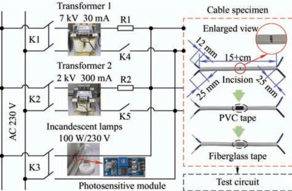
Fig.1 Preparation circuit of carbonized cable specimen
The standard IEC 62606 states: “It shall be permissible to modify the test circuit such that current does not flow through the device under test during the high voltage conditioning cycle[13].” Therefore,a carbonized cable specimen preparation circuit was devised as shown in Fig.1.Circuits for 7 kV/2 kV high-voltage carbonization,cable sample detection,and experiments were independent of each other.K1 and K4 were used to create a closed loop of a 7 kV circuit,whereas K2 and K5 were used to create a closed loop of a 2 kV circuit.K3 was implemented to create an incandescent lamp detection circuit,and R1 and R2 served as current-limiting resistors.
2.2 Phenomenon of cable preparation process
The carbonization of cable insulation is a complex process in high-voltage grid operations that involves an electrical tree,electrical breakdown,main discharge,and other phenomena.This study adhered to the standard low-voltage arc fault test procedure,in which cable specimens underwent special treatment,such as cutting,before applying a high voltage to rapidly form a carbonized conductive path in the incision.
During the energization process at high voltage,smoke was produced at the cut-out of the cable specimen.This smoke then spread from both sides of the wrapped tape or the end of the cable,as shown in the top panel of Fig.2a.The spattering of the high-temperature particles depends on the incision size,as shown in the lower panel of Fig.2a.Fig.2b shows the development of carbonized conductive paths within the incision,which were captured by a high-speed camera,where I and II correspond to the beginning and end of the 7 kV and 2 kV energization processes,respectively.Applying a high voltage of 7 kV to the incision breaks down the conductors,leading to a slight carbonization effect due to changes in the molecular structure of the insulation material and degradation of its insulation properties.The secondary application of a 2 kV high voltage expedites the accumulation of carbon residue,ultimately forming a stable carbonized conductive path.Fig.2c shows the external temperature of the cable specimen captured by an infrared thermal imaging camera during 7 kV energization,2 kV energization,and completion of preparation.Electrical breakdown and discharge occurred between the conductors in the incision,causing the cable specimen temperature to be notably concentrated at the incision site.Consequently,the internal temperature is expected to be higher.The temperature remained stable during the 7 kV energization process,whereas it gradually increased throughout the 2 kV energization process,reaching its maximum level after high-voltage energization.The thermal decomposition of polyvinyl chloride insulation materials was previously analyzed in Refs.[17-18].Moreover,the accumulation of heat throughout this process can cause burning holes in the insulation skin of the cable specimen near the power supply side,as shown in Fig.2d,for both prepared cable samples.This burning effect can potentially lead to the loss of carbon residue from the carbonized conductive path.This phenomenon is consistent with the results shown in Figs.2a and 2c.
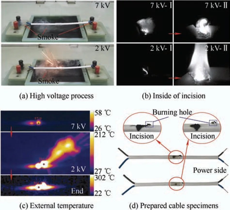
Fig.2 Phenomenon of the cable preparation process
Carbonized cable specimens that have been energized with high voltages of 7 kV and 2 kV should be connected to the K3 circuit shown in Fig.1 for detection.Typically,the carbonized conductive path is deemed integral (successful preparation) when a 100 W incandescent lamp emits light or an equally resistive resistor produces a circuit current of 0.3 A under the rated 230 V conditions.The cable specimen needs to be connected to the main circuit of the arc fault test,where the arc fault circuit interrupter/AFDD is situated,to undergo testing.
3 Analysis of carbonized conductive path
The quality of carbonized conductive paths during specimen preparation is affected by numerous factors,including but not limited to energization time,creepage distance,cutting method,incision size,specimen type,high voltage power,and manual operator errors.Even if certain factors,such as the cutting method and high-voltage power,are determined,differences arising from manual operation and environmental conditions (such as the geometric characteristics of the incision,temperature,and humidity in the laboratory) remain inevitable.Consequently,the high-voltage energization time was a crucial factor in regulating the carbonization degree of the cable specimens during the carbonized cable preparation process.
The UL 1699 (Section 40.4.2),IEC 62606 (Section 9.9.2.6),and GB/T 31143 (Section 9.9.2.6) standards share identical requirements for high-voltage energization during cable specimen preparation.For example,IEC 62606 stipulates the following.
“f) The cable specimen is to be connected to a circuit providing 30 mA short circuit current and an open circuit voltage of at least 7 kV.The circuit is to be energized for approximately 10 s or until the smoking stops.
g) The cable specimen is to be connected to a circuit providing 300 mA short circuit at a voltage of at least 2 kV or sufficient to cause the current to flow.The circuit is to be energized for approximately one minute or until the smoking stops.”
The reliability of the carbonized conductive path formed by the above operation is questionable based on the experimental results.Consequently,overcarbonized cable specimens are frequently produced,and even a minimal current test at the rated voltage of 230 V results in experimental failure.Fig.3 shows the different current waveforms detected in the cable specimens as the high-voltage energization time increased during the preparation process.The characteristics of the current detection waveforms allow the categorization of preparation outcomes into U-CZ,S-CZ,short-circuit-CZ(SC-CZ),and open-circuit-CZ (OC-CZ).
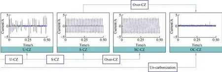
Fig.3 Different current waveforms detected in the carbonized cable samples
Uncarbonized cables are cable specimens that have not received high-voltage energization or have undergone insufficient energization,which creates little carbon residue in the incision.BVVB-type cables are an example in which insufficient energization fails to adequately damage a conductor.In this case,the detection current waveform was OC-CZ,and a loop connected to the low-voltage test circuit was not formed upon energization.
Insufficient energization leads to U-carbonized cable specimens by providing insufficient carbon residue in the incision,thus not achieving S-CZ.For instance,RV-type cables with many conductors and small diameters,if energized for a brief period,lead to less carbon residue being dispersed on the conductors,resulting in unstable carbonized conductive paths and prone to U-CZ.Such cable specimens are particularly susceptible to intermittent arcing during testing or after the current crosses zero.The effect of the U-carbonized cable specimens was more significant during tests conducted under 120 V-rated voltage conditions.
S-CZ was achieved by selecting an appropriate high-voltage energization time.Successfully carbonized cable specimens exhibited stable current patterns with slight variations between the half-waves.Once connected to a test circuit,the cable specimens produced arc faults that adhered to the repeatability and duration criteria established in the testing standards.Continued high-voltage applications can cause the S-carbonized cable specimens to rapidly transition to an over-CZ state,such as SC-CZ or OC-CZ.
In SC-CZ,the carbon residue inside the incision solidifies to form a dense,rod-like structure.Its conductivity was similar to that of an unseparated carbon electrode in an arc generator.High-temperature arcs can also cause SC-CZ by melting the BVVB-and BVR-type cable conductors at the incision point to form highly conductive metal bridges.The SC-carbonized cable specimens were used to create fully conductive test circuits,rendering them incapable of producing arc faults.
In the OC-carbonized cable specimens,energy accumulation caused the carbon residue inside the incision to spray upward,leftward,and rightward,with gas breaking through at the incision’s weakest point under pressure.A break in the carbonized conductive path can lead to carbonization failure.Another way that OC-CZ can also occur when RV-type cable conductors overheat the incision,leading to conductor fracture.The OC-carbonized cable specimens yielded the same results as the uncarbonized specimens.
The above results cover all the results of cable preparation.A theoretical intermediate state exists where S-CZ advances to over carbonization.However,obtaining samples at this stage has proven difficult because of the ease with which S-CZ can progress to an over-carbonized state during high-voltage energization.The detection current waveform reveals that the incandescent lamp-based discrimination method cannot accurately differentiate among the four preparation results of the carbonized cable specimens.Cable specimens with S/SC-CZ and those partially prepared for U-CZ were deemed successful.Conversely,for the cable specimens in which the OC-CZ and another part of the U-CZ failed.
4 Optimization control strategy
4.1 Detection algorithm of preparation results
After comparing the waveforms of the four types of detection currents,no half-wave was observed in the detection current of OC-CZ.Its value is approximately zero,similar to the characteristics of noisy signals.By contrast,the current signals detected in the other three cases displayed periodic or intermittent waveforms.Therefore,by utilizing this distinction,one can apply a threshold value can be applied in combination with the original signal or its RMS to filter out the OC-CZ signal.For the detection process,a periodic moving RMS-based algorithm can be employed based on the concept of the moving average filter algorithm[19-20]
wherei(τ) is the input signal;Tnis the moving window length.The power frequency was 50 Hz andTn=0.02 s.The difference in the RMS values between SC-CZ and S-CZ was dependent on the resistance of the carbonized conductive path.Similarly,the difference in the RMS values between S-CZ and U-CZ was affected by the degree of burning in the intermittent arc.Consequently,the three types of RMS results were aliased.
As the arc current follows the periodicity of the AC power supply,the waveform of the S-CZ current also follows a similar periodicity and displays half-wave symmetry to that of SC-CZ.By creating a suitable moving window,these two signals can be filtered using a moving average filter algorithm[21].However,owing to the intermittent half-wave loss,the algorithm could not entirely attenuate the current waveform of the U-CZ.Therefore,depending on the difference in the averaging outcomes,a threshold can be defined to differentiate the U-CZ signal from the other two current signals.For detection,the periodic moving average algorithm can be represented as
The difference between the periodic average values of SC-CZ and S-CZ was minimal,except for the slight randomness caused by the arc combustion,which may confound the results.
The remaining SC-CZ and S-CZ cases are equivalent to normal operation and arc faults under resistive load conditions,respectively.The arc extinguishes near the over-zero point of the AC power supply and lingers for a short time at the zero crossing[22].Therefore,a threshold can be established to differentiate the periodically moving shoulder percentages between the detection currents of SC-CZ and S-CZ.To mitigate the effects of current signal acquisition noise,the shoulder threshold was calculated using the 5% RMS value of the current signal within the power supply period.A shoulder is recorded as “1” if the current signal falls within the threshold
The equation for calculating the shoulder percentage usingnTas a moving window is as follows
whereTsdenotes the sampling period.
4.2 Discrimination process of preparation results
Fig.4 shows a flowchart of the carbonized cable discrimination method based on the algorithm described above.Following the cable preparation,the current flowing through the carbonized conductive path was acquired in the K3 loop.Each of the three period-moving algorithms operates with a calculation period of 10 moving windows,equivalent to 0.2 s.Respectively,the thresholds Th1,Th2,and Th3,aligned with the three moving algorithms in the discriminative method,are established.First,theIRMSof the detection current signal for the carbonized cable specimen was calculated using Eq.(1) and compared with Th1to identify OC-CZ.Next,IMeanof the detection current signal was computed for the remaining three carbonized cable specimens using Eq.(2) and compared with Th2to differentiate the U-CZ.Finally,IShoulderof the detection current signal for the carbonized cable specimen was determined using Eq.(4) and compared with Th3to distinguish between S-CZ and SC-CZ.Thus,by utilizing three periodic moving algorithms (RMS,average,and shoulder percentage),all four outcomes of the carbonized cable preparation can be accurately differentiated.
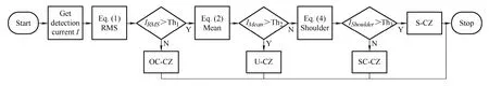
Fig.4 Discrimination flow of carbonized cable preparation results
The main factors influencing the selection of thresholds include noise induced by data acquisition and random variation in the dynamic process of arc faults.The minor disturbances conformed to a normal distribution.Average and standard deviation of the output signals of the three algorithms in Tabs.1-3 were calculated by examining several groups of carbonized cable specimens.To ensure accurate discrimination,the thresholds for several cases of the output signal were selected using the 6-sigma principle.This principle ensures that almost 99.999 66% of the data falls within six standard deviations.Based on the statistical results ofIRMS,IMean,andIShoulderfor the different carbonized cables in Tabs.1-3,the threshold selection was 0.024 5 forIRMS(Th1),0.149 8 forIMean(Th2),and 0.028 6 forIShoulder(Th3).

Tab.1 IRMS statistics of carbonized cable specimens
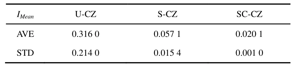
Tab.2 IMean statistics of carbonized cable specimens

Tab.3 IShoulder statistics for carbonized cable specimens
4.3 Control strategy of preparation process
According to the analysis in Section 3,both the U-carbonized and partially OC-carbonized cable specimens can be re-carbonized to achieve the desired carbonization level.OC-CZ can occur because of uncarbonization,over-CZ,or shallow U-CZ and can be remedied by applying the primary high-voltage energization time to carbonize or re-carbonize.Fig.5 shows the control strategy used in the preparation of the carbonized cable specimen.Tis the primary high-voltage energization time.According to the standard,the ratio of the 7 kV and 2 kV high-voltage energization times is 1:6;thus,T=[T7kV,T2kV]=[2 s,6 s].To prevent the re-carbonization of samples with broken cable conductors,a counter was implemented to keep track of the number of times a single preparation experiment was identified as OC-carbonized.If the count was below 3,re-carbonization was carried out;otherwise,the preparation of the carbonized cable specimen was deemed unsuccessful.
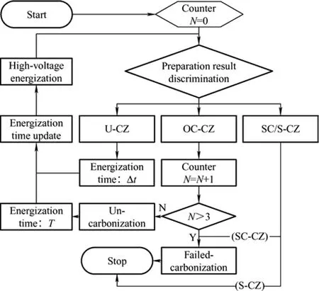
Fig.5 Control strategy of preparation process
If a U-carbonized cable specimen is obtained,it can be re-carbonized by adjusting the high-voltage energy time.The arc stability can be calculated based on the degree of waveform loss of the detection current.
whereTmis the selected calculation period,Tm=0.2 s;nis the number of arc fault half-wave withinTm.The determination of the half-wave number depends on whether the detection current signal meets the 5%RMS value of the current in the absence of arc fault.Any waveform that falls below the threshold is considered to be as lost at half-wave.The high-voltage energization time required for the re-carbonization of the U-carbonized cable specimen is determined based on the arc stability duringTm
Re-carbonizing an SC-carbonized cable specimen may not necessarily rectify this issue because it can continue to retain the SC-CZ state.Furthermore,secondary breakdown and high temperatures can cause tape or cable insulation in the vicinity of the incision to melt or break,resulting in irreversible OC-CZ.Therefore,this condition is considered to be a failure in the preparation of the carbonized cable specimens.
5 Experimental verification
The proposed algorithm was tested on an experimental platform,as detailed in Section 2.1,to validate the feasibility of the discrimination method and control strategy for preparing carbonized cable specimens.To switch the circuit on and off,the host computer automates the preparation and testing processes by sending control commands through a data-acquisition card.The relay-control board manages the contactors to switch between different loops and regulates them on time.The data acquisition card was instrumental in collecting data from the current sensor,which measured the current signal during the detection and testing of the carbonized cable specimen.The cable samples had cutout sizes ranging from 2 mm to 5 mm.
Fig.6 shows the waveforms of the original detection currents and their respective moving RMS values for the four different types of carbonized cable specimens.The results showed that,compared to the three other preparation methods,the periodic moving RMS values with OC-CZ are significantly more stable.The cable specimens with OC-CZ were identified using the threshold (Th1).The incandescent lamp-based discrimination method indicated that the cable specimens with OC-CZ could not establish a circuit loop in the detection circuit,resulting in the incandescent lamp staying in OFF mode.This observation was consistent with the results of the discrimination method used in this study.

Fig.6 Original and RMS signals of carbonized results
Fig.7 shows the periodic moving-average waveforms of the detection currents for the U/SC/S-CZ cable specimens.Owing to its periodic symmetry,SC/S-CZ has approximately zero periodic moving average values.The S-CZ cable specimens had a degree of fluctuation similar to that of the theoretical analysis,resulting from the randomness of the arc combustion process.However,owing to the intermittent half-wave loss,the U-CZ cable specimens have a notable overshoot in the periodic moving average waveform.Half-wave loss causes a flickering phenomenon when using the incandescent lamp-based discrimination method in detecting the U-CZ,making it challenging to distinguish the cable specimen results.Utilizing the threshold (Th2) of the proposed method,U-CZ could be distinguished from the three preparation methods,avoiding misjudgment.
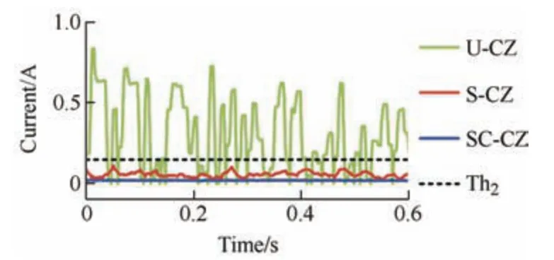
Fig.7 Comparison of moving average signals
Fig.8 shows the periodically moving shoulder percentage of the detection current for the SC/S-CZ cable specimens.The cable specimens with SC-CZ exhibited a stable shoulder percentage of 2%-2.5%.In contrast,the cable specimen with S-CZ had an increased shoulder percentage when the arc reignites,as indicated by the red line in Fig.8,which ranged from 5% to 15%.Incandescent lamps were emitted in both cases,thus making it difficult to differentiate the two cable specimen types using this method.However,the proposed discrimination method can effectively classify the two types of carbonized cable specimen preparation results using a threshold (Th3).
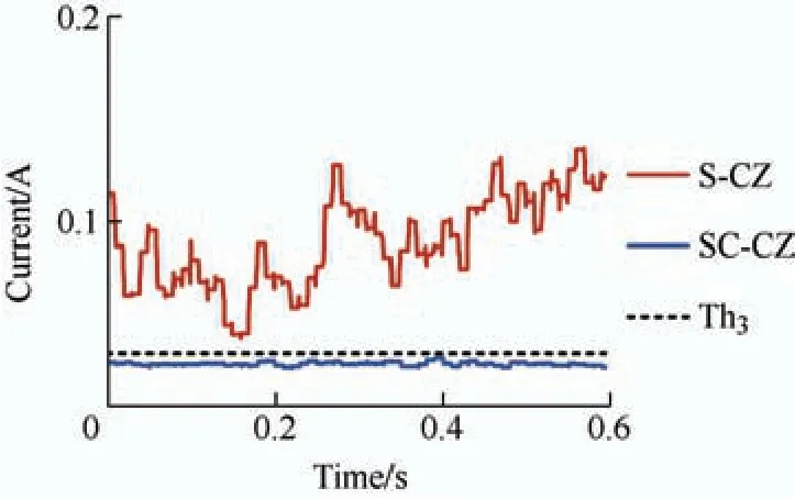
Fig.8 Comparison of moving shoulder percentage signals
The validity of the proposed discrimination method is confirmed by the aforementioned results and analyses.To optimize the preparation results,the control strategy in Section 4.3 adjusted the high-voltage energization time during the carbonization process.Preparing 100 sets of carbonized cables and conducting arc fault tests with different loads demonstrated the effectiveness of this strategy in improving the success rate of carbonized cable specimen preparation.Fig.9 shows the current waveforms of the specimen prepared using the proposed method for arc fault tests at different current levels,which meet the requirements of arc duration for different tests and the operating characteristics testing of the AFDDs.Among them,the test requirements in the GB/T 31143 standard state that the arc duration needs to exceed 1 s for 3 A current level at a rated voltage of 230 V,0.5 s for 6 A,0.25 s for 13 A,and 0.15 s for 20 A.
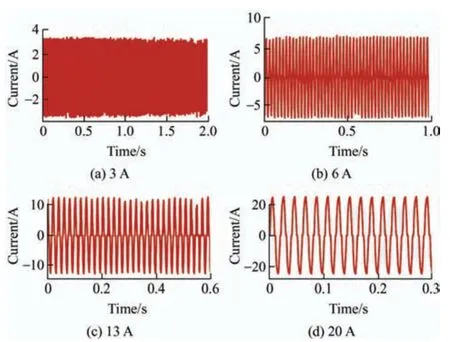
Fig.9 Test of carbonized cable specimens
6 Conclusions
Carbonized cables are one of the main reappearances for testing low-voltage arc faults.Improving the success rate of carbonized cable preparation is essential for the research and verification of arc fault detection and protection technology.To address the difficulty in identifying the carbonized cable preparation results,this study proposes a cable specimen discrimination method based on periodic moving algorithms of the RMS,average,and shoulder percentages.Compared to the method based on incandescent lamps,this method can identify the categories of different cable specimens more precisely and accurately.Based on this method,a control strategy for the preparation of carbonized cable specimens that can automatically adjust the high-voltage energization time was proposed to improve the success rate of carbonized cable preparation.The proposed discrimination and control strategies were evaluated using a carbonized cable experimental platform.The test results demonstrate the efficacy of the proposed discrimination method in controlling the cable preparation process,with the prepared cable specimens satisfying the arc-fault persistence test requirements.The proposed method is also suitable for conducting low-voltage arc fault tests at 120 V.
The proposed control strategy can be used to prepare U-CZ cable specimens by controlling the high-voltage energization time.Experiments using U-carbonized cable specimens can simulate the entire development of arc faults from initiation to stable combustion.This method is suitable for researching and verifying arc fault warning and detection algorithms.Early detection of arc faults through this type of test will subsequently lower the probability of ignition.
杂志排行

Chinese Journal of Electrical Engineering的其它文章
- Comparative Analysis of Vibration and Noise of Axial Flux Motor with Different Pole and Slot Combinations*
- Power Quality Improvement and Signal Conditioning of PV Array and Grid Interfaced Off-board Charger for Electric Vehicles with V2G and G2V Capabilities*
- A Novel Modified Fuzzy-predictive Control of Permanent Magnet Synchronous Generator Based Wind Energy Conversion System
- Improved Approaches Toward Analysis of Electromagnetic Processes in Electrodynamical Devices Based on the Theory of Electromagnetic Field
- Filtered High Gain Observer for an Electric Vehicle’s Electro-hydraulic Brake: Design and Optimization Using Multivariable Newton-based Extremum Seeking
- Calculation of Available Transfer Capability Using Hybrid Chaotic Selfish Herd Optimizer and 24 Hours RES-thermal Scheduling