A Novel Modified Fuzzy-predictive Control of Permanent Magnet Synchronous Generator Based Wind Energy Conversion System
2024-01-16
(1.Department of Electrical Engineering,Mazandaran University of Science and Technology,Babol 4716685635,Iran;2.Department of Electrical Engineering,Islamic Azad University,Bojnourd Branch,Bojnourd 9417697796,Iran)
Abstract: A wind energy conversion system (WECS) based on a permanent magnet synchronous generator (PMSG) is an effective solution for renewable energy generation in modern power systems.The main advantages of PMSG include high performance at high and low speeds,minimal control effort owing to lower rotor inertia,self-excitation,high reliability,and simplicity of structure compared with induction generators.However,the intermittent nature of wind energy implies that maximum efficiency is not obtained from this system.Accordingly,maximum power point tracking (MPPT) in wind turbine systems has been proposed to address this problem.Traditional MPPT strategies suffer from severe output power fluctuations,low efficiency,and significant ripples in turbine rotation speed.This paper presents a novel MPPT control strategy based on fuzzy logic control (FLC) and model predictive control(MPC) to extract the maximum power from a PMSG-WECS and control the machine-side and grid-side converters.The simulation results obtained from Matlab/Simulink confirm the superiority of the control model in eliminating the output power fluctuations of the wind generators and accurately tracking the maximum power point.A comparative study between conventional MPPT and control methods is also conducted.
Keywords: Maximum power point tracking (MPPT),wind energy conversion system (WECS),permanent magnet synchronous generator (PMSG),fuzzy logic control (FLC),model predictive control (MPC)
1 Introduction1
Renewable energy is a promising solution for addressing the problems caused by global climate change.In the future electricity industry,renewable energy sources are vital for increasing energy security and reducing environmental pollutants[1].A wind energy conversion system (WECS) based on a permanent magnet synchronous generator (PMSG) is advantageous for converting mechanical energy into electrical energy[2].The system is connected to the power grid via two AC-DC and DC-AC converters:the machine-side (MS) and grid-side (GS) converters.Various parameters in a wind turbine (WT) system affect the power generation and efficiency of the entire system,including the wind speed,blade pitch angle,and conversion efficiency of converters.In addition,the stability of a WECS depends on wind speed,which is an uncertain parameter.Linear control strategies such as proportional-integral (PI) control have been widely used to control wind turbines.However,the major drawbacks of linear controllers include high sensitivity to external disturbances,slow transient responses under faulty conditions,poor robustness to reactions to the nonlinearity of the system and uncertainties in wind speed and wind turbine parameters[3].For these reasons,it is necessary to use nonlinear control models to control the MS and GS converters.The primary purpose of these control models is to extract maximum power from the wind energy conversion system,eliminate wind turbine output power fluctuations,and regulate the voltage and frequency on the grid side by controlling the grid-side active and reactive powers,respectively.
Consequently,numerous maximum power point tracking (MPPT) algorithms for wind turbine systems have been presented[4].In general,these techniques can be divided into four categories: indirect power control (IPC),direct power control (DPC),hybrid and intelligent algorithms.Traditional IPC models such as the tip speed ratio (TSR),power signal feedback(PSF),and optimal torque control (OTC) have been used in various studies[5-9].However,low efficiency,inadequate reliability,high installation and maintenance costs,and the need for the mathematical model of the wind turbine are some of the drawbacks of these techniques.In addition,DPC algorithms,such as P&O and INC,have been widely used in the literature[10-12].The main challenge associated with these methods is determining an appropriate step size near the maximum power point.If the step size is large,it causes power fluctuations;if it is small,the response time of the model to changes in wind speed increases.To address these challenges,hybrid[13-14],modified[15-18],and optimized[19-20]versions of traditional indirect and direct power control algorithms have been presented.These hybrid and modified methods solve challenges associated with conventional algorithms.However,the power fluctuations around the maximum point and slow transient response under sudden wind speed changes remain unsolved.Therefore,intelligent MPPT algorithms have been presented to eliminate power fluctuations around the maximum power point and improve controller performance under varying wind speed conditions[21].
The most common intelligent controllers used in these studies include sliding mode control (SMC)[22-25]and fuzzy logic control (FLC)[26-30].The slow coverage speed and high total harmonic distortion of the PMSG terminal currents are two major problems in the SMC method[25,31].Nevertheless,the traditional fuzzy logic control model also has several weaknesses,e.g.,high memory requirement,definition challenges associated with membership functions,and rule base dependency on adequate system knowledge[4,32].To address these problems,modified FLC and SMC models have recently been presented,such as a neuro-adaptive generalized global sliding mode controller[33],discrete-time integral terminal sliding mode controller[34],dimensional fuzzy logic control[35],signed-distance fuzzy logic control[36],and an adaptive fuzzy logic controller[37-39].Some intelligent controllers presented in the literature rely on optimization algorithms,but their performances are diminished by premature convergence or the curse of local optimality[40-43].
Model predictive control (MPC) is an efficient method for controlling nonlinear systems and has been widely used owing to its high accuracy and rapid dynamic performance[44-46].The main weakness of MPC is its limitations owing to the large number of calculations in a small sampling time,which increases the computational burden[47].To solve this problem,finite control set model predictive control (FCS-MPC)has been proposed,which reduces the computational time required to optimize the objective function by limiting the switching numbers of the power converter[48-50].In addition,modified versions of MPC have been presented,such as multi-vector MPC[51]and extended state observer-based MPC[52],which have solved the limitations of the classic MPC model.However,the extended state observer-based MPC extends the response time of the control system,despite solving the problem of load uncertainties in a PMSG-based wind energy conversion system.Likewise,the multi-vector MPC cannot reduce the total harmonic distortion (THD) of the PMSG terminal currents,despite addressing the current ripple problem of the classic model predictive controller.
To overcome the challenges of classical MPC and its modified versions,this study proposes a hybrid model based on a fuzzy logic controller and a model predictive controller to control the MS and GS converters in a PMSG-WECS.In the machine-side controller,only the PMSG terminal current sensor is required.In addition,the controller performance in tracking wind speed changes is considerably improved compared with traditional MPPT-based controllers,owing to the use of the FLC to determine theq-axis component of the reference current.In addition,in the grid-side controller,thed-axis component of the reference current was obtained by utilizing the FLC based on the DC bus voltage.The high precision of the FLC in adjusting the DC bus voltage causes the GS active power to exhibit a fast dynamic response with minimal fluctuations around the reference value.Additionally,MPC exhibits excellent performance in tracking the reference trajectory of the control variable owing to its ability to predict the behavior of the system in the future[53].Moreover,unlike traditional maximum power point tracking models,MPC offers flexibility for inputs and control variables.Therefore,any reference generation scheme can be combined with MPC.On the other hand,the main advantage of fuzzy logic control is determining the optimum reference value based on control inputs[54].Accordingly,by combining the fuzzy control model as the reference generator and model predictive control as the reference tracker,a MPPT model with excellent performance can be obtained.The innovations and advantages of this study are as follows.
(1) Designing MS and GS controllers based on the same FLC-MPC control structure.
(2) Improving the performance of the MPPT-based controller of the MS converter in terms of extracting the maximum power with minimal fluctuations around the maximum power point compared with traditional MPPT algorithms.
(3) The grid-side active power fluctuations are reduced compared to those of other controllers proposed in the literature.
(4) Three-phase PMSG terminal current harmonics are significantly reduced.
(5) The GS converter is controlled under power factor conditions of unity.
The remainder of this paper is organized as follows.In Section 2,the PMSG-based wind energy conversion system is described.Additionally,the mathematical model of the permanent magnet synchronous generator is presented in this section.Section 3 describes the proposed MPPT controller based on the combined fuzzy logic MPC.The results of the simulation efforts and comparative studies are presented and investigated in Section 4.Eventually,Section 5 summarizes and concludes the paper.
2 PMSG-based wind energy conversion system
The structure of a PMSG-based wind energy conversion system is shown in Fig.1[10].In this system,two AC/DC and DC/AC converters are used to transfer the generated power of the wind turbine to the grid.Each converter requires a separate controller to track the maximum power point and simultaneously regulate the voltage and frequency.
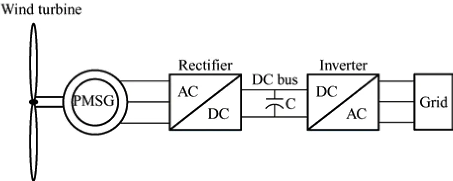
Fig.1 PMSG-based wind energy conversion system
The stator voltage in a permanent magnet synchronous generator in thed-qreference frame is expressed as follows[32]
whereRsdenotes the resistance of the stator phase,andωesignifies the angular speed of the generator.λsdandλsqindicate thed-qstator flux components,which are defined as follows
whereφsdenotes the magnetic flux,LsdandLsqindicate the statordandqaxes self-inductances,respectively.In a PMSG,the electromagnetic torque is calculated as follows
In Eq.(3),Pindicates the number of pole pairs.
3 Proposed control model
To track the maximum power point under varying wind speed conditions and regulate the GS voltage and frequency in a PMSG-based WECS,a hybrid fuzzy logic model predictive controller FLC-MPC is proposed.Two independent controllers are designed based on the FLC-MPC model for the machine-and grid-side converters.Both controllers have the same configuration,while the control mechanism and variables are distinct.The proposed control models are described in the following sections.
3.1 Machine-side converter controller
To design a control model for the machine-side converter,Eq.(3) is converted into a linear form.If thed-axis component of the stator current is zero,then Eq.(3) is converted into a linear form,and theq-axis component of the stator current reference value can be derived via
The reference value ofωewas calculated as follows[19]
where,vdenotes the rated wind speed,rindicates the length of the wind turbine blades,andλoptdenotes the optimum tip speed ratio of the wind turbine.An empirical formulation forλoptwas obtained using the trial-and-test method assuming zero pitch angle,which is a valid assumption for low and medium wind speeds[20].
whereωe_rateddenotes the nominal (/reference)rotational speed of the PMSG.Based on the aforementioned formulations,the proposed MS converter controller is shown in Fig.2.
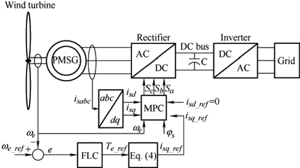
Fig.2 Proposed control model for MS converter
In this control model,the difference between the real-time angular speed of the generator (ωe) and its reference value (ωe_ref) is applied to the FLC block.The FLC controller comprises three parts:fuzzification,fuzzy rules,and defuzzification,as illustrated in Fig.3.The inputs of this block include the PMSG speed error (e) and delta error (Δe),which are specified as follows[32]

Fig.3 FLC block diagram associated with the MS controller
wherez-1represents the memory operator that stores the value of the parameter in the previous step and applies it to the controller in the current step.The output of the FLC block is the reference value of the electromagnetic torque,Te_ref.This quantity is computed by summing the incremental electromagnetic torque (ΔTe) andTe(k-1).In the FLC block diagram,coefficientski(i=1,2,3) perform as the normalization gains.
The membership functions (MFs) associated with the input and output parameters are depicted in Fig.4.Fig.5 shows the fuzzy logic rule surface.In addition,the fuzzy rules listed in Tab.1 are applied to the“Fuzzy rules” block.In this study,the center of gravity(CoG) method was utilized for the defuzzification block[36].In this method,the output of the defuzzification block (ΔTe) is obtained using Eq.(9)based on the membership functions shown in Fig.4.
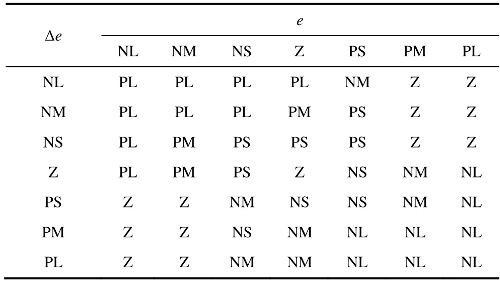
Tab.1 Rules table for fuzzy inference system

Fig.4 Membership functions used for input and output variables

Fig.5 Fuzzy logic rule-surface
wherenindicates the number of fuzzy sets.μfirepresents the membership function that corresponds to thei-th region shown in Fig.4.Additionally,xiandAicorrespond to the center and area of thei-th MF,respectively.Subsequently,MPC was used to generate the switching signals of the rectifier.Thed-qaxis stator currents of the PMSG are applied as inputs to the MPC block,and the stator voltages are derived in the form of command signals using Eqs.(10)-(13).
Assuming constant magnetic fluxφs=0) in a PMSG and referring to Eqs.(1) and (2),we obtain
By discretizing the above equations,the following equations can be obtained[55].
By minimizing the cost function expressed in Eq.(13),the stator voltage command signals are generated and the switching signals of the MS converter can be derived using the pulse width modulation (PWM)technique.
whereTsdenotes the switching period (Ts=1/fs,wherefssymbolizes the switching frequency),usd_comandusq_comrepresent thed-qaxis stator voltage command signals.A block diagram of MPC is shown in Fig.6.
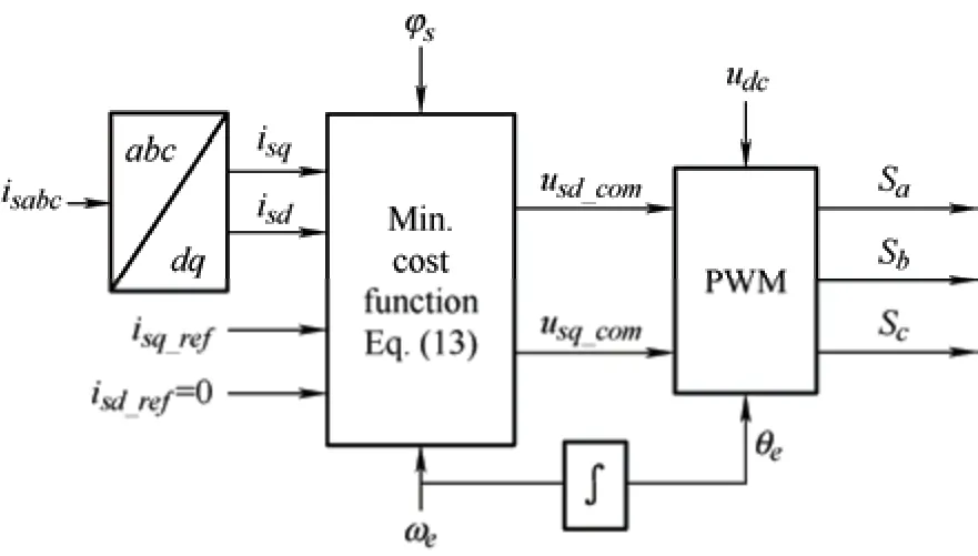
Fig.6 Block diagram of MPC associated with MS controller
3.2 Grid-side converter controller
A similar controller based on the combined FLC-MPC model was implemented for the GS converter.The main difference is that the FLC inputs are determined based on the DC-link voltage and its reference value.Suppose the three-phase grid-side voltages are defined as follows
whereEindicates the maximum voltage andωsymbolizes the angular frequency of the network.Furthermore,the voltage equations for the grid-side converter are derived as follows
whereLdenotes the grid-side coupling inductance;ia,ib,andicindicate the grid-side three-phase currents,andva,vb,andvcindicate the three-phase voltages measured on the inverter terminal.By converting the voltage equation in Eq.(15) tod-qcoordinates,we obtain
In Eq.(17),Pgdenotes the GS active power.The GS converter controller generates reference currents so that pure active power is delivered to the grid.Therefore,to operate the proposed controller under unity power factor (UPF) conditions,the reference current parallel to theq-axis must be zero,that is,iq_ref=0.Hence,Eq.(17) is converted to
In the grid-side FLC block,the controller inputs are
Moreover,the FLC output is ΔPg.Accordingly,a block diagram of the grid-side controller was obtained,as shown in Fig.7.The FLC design procedure is similar to the MS converter controller;it involves enteringedcand Δedcas inputs and deriving ΔPgas the output based on Eq.(9).The fuzzy rules and membership functions are defined in the same manner as in the MS converter FLC.However,to generate switching signals using MPC,the following equations were employed

Fig.7 Proposed control model for GS converter
In the above equations,Tsindicates the switching period,which is the inverse of the switching frequency of the grid-side converter.In addition,vd_comandvq_comrepresent the voltage command signals that produce the switching signals of the inverter using the PWM block.By applying MPC and minimizing the objective function in Eq.(24),the voltage command signals can be generated for the GS converter.
In Eqs.(13) and (24),c1,c2,c3,andc4are the weighting coefficients.A block diagram of the MPC applied to the grid-side converter is shown in Fig.8.
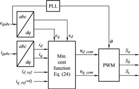
Fig.8 MPC block diagram associated with GS controller
4 Simulation results
In this section,to evaluate the capability of the proposed FLC-MPC controller for MS and GS converters,a PMSG-based wind energy conversion system connected to a three-phase network is simulated in Matlab/Simulink R2018b based on the parameters listed in Tab.2.Next,the proposed MS and GS controllers were applied to this system.The characteristic curves of the wind generator at different wind speeds are shown in Fig.9.Fig.10 shows the wind speed profile for the simulated system.To evaluate the performance of the proposed control model,traditional MPPT algorithms,that is,P&O[11,26],INC[10],and traditional FLC[25-26],were also implemented in the simulation model,and the results are compared with those of the proposed control model.The output power and rotational speed of the WT generator are shown in Figs.11 and 12,respectively.
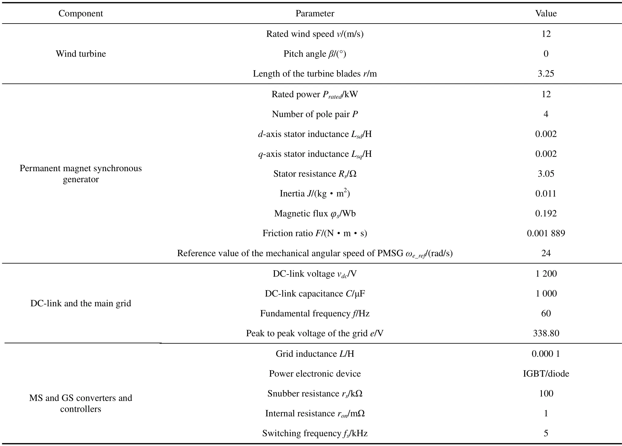
Tab.2 Simulation parameters
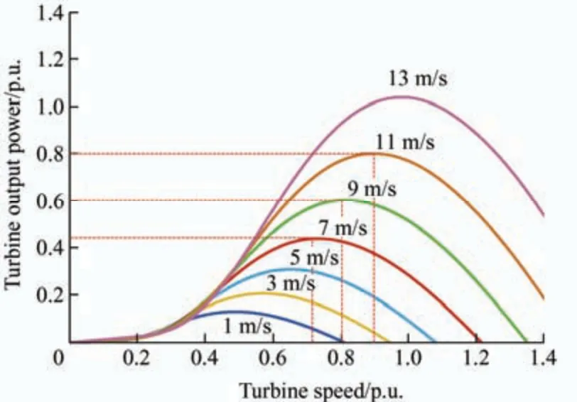
Fig.9 Characteristic curves of the WT for different wind speeds
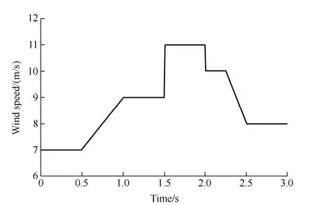
Fig.10 Wind speed profile for the simulated system
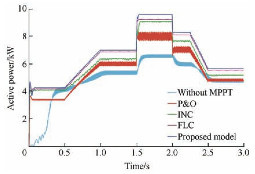
Fig.11 Output power of the WT generator

Fig.12 Rotational speed of the WT generator
Fig.13 shows the voltage and current measured at the PMSG terminal.In this figure,the voltage and current waveforms are compared for two scenarios:one without MPPT and the other with MPPT-based FLC-MPC.By implementing the proposed MPPT model,the line-to-line current of the PMSG terminal is boosted,and the current and voltage waveforms exhibit negligible transient state dynamics.This indicates the superior performance of the proposed controller in tracking wind speed changes with high accuracy.
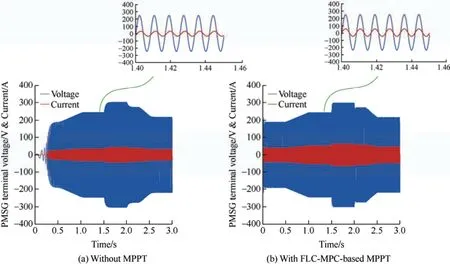
Fig.13 PMSG terminal voltage and current waveforms
In this section,the performance of the proposed controller in controlling a grid-side converter is evaluated.In this study,the reference value of the DC-link voltage (vdc) was 1 200 V.Fig.14 shows the actual DC-link voltage obtained by applying the proposed FLC-MPC controller to the GS converter.In the proposed controller,the grid-side active power depends on thed-axis current component and changes in wind speed,as shown in Fig.15.However,the reference value of theq-axis current is zero to guarantee the UPF operation of the GSC.Hence,the proposed controller operates such that theq-axis current becomes zero,as shown in Fig.16.To verify the performance of the proposed FLC-MPC controller on the GS converter,the controller presented in Ref.[15] and Ref.[17] was simulated,and its results are compared with those of the proposed controller shown in Figs.15 and 16.In Ref.[15] and Ref.[17],a voltage-oriented control method was implemented on a grid-side converter comprising two PI-based control loops.The outer loop regulates the DC-link voltage,while the inner loop controls the active power on the grid side.The grid-side active and reactive powers obtained by applying the controller proposed in this study and the controllers presented in Ref.[15] and Ref.[17] are shown in Figs.17 and 18,respectively.It is evident that the proposed FLC-MPC controller can produce active power more smoothly with lower transient-state dynamics under varying wind speed conditions.Furthermore,attenuation of the GS reactive power by applying the proposed FLC-MPC controller is significantly better than those of the controllers presented in Ref.[15] and Ref.[17].

Fig.14 DC-link voltage
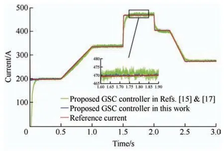
Fig.15 d-axis current by applying grid-side controller
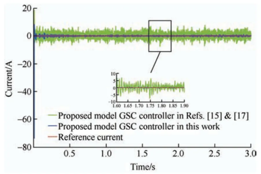
Fig.16 q-axis current by applying grid-side controller
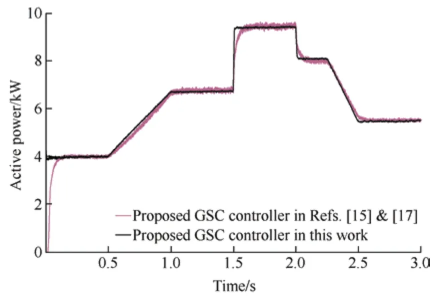
Fig.17 Grid-side active power
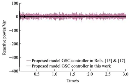
Fig.18 Grid-side reactive power
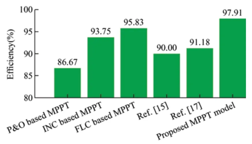
Fig.19 Efficiency computed for MPPT algorithms
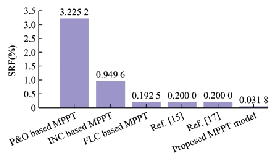
Fig.20 SRF computed for MPPT algorithms
The results of the numerical investigations are listed in Tab.3 to verify the excellent performance of the proposed MPPT model.The first column in Tab.3 provides the peak-to-peak speed ripple for various MPPT strategies,and the second column lists the speed ripple factor (SRF),which is calculated as follows[56]

Tab.3 Comparison between the proposed model and the other MPPT algorithms for PMSG-WECS
whereωp-pindicates the peak-to-peak speed ripple,andωavedenotes the average speed of the wind turbine generator.The fourth and fifth columns in Tab.3 provide the settling time and efficiency of the MPPT algorithm,respectively.The proposed FLC-MPC technique exhibits the highest efficiency and lowest SRF.The variable-step P&O algorithm proposed in Ref.[17] demonstrates the extremely short settling time at the cost of poor efficiency and high SRF.Graphical representations of the efficiencies and SRF values that correspond to the MPPT algorithms are shown in Figs.19 and 20,respectively.The negligible value of the SRF (0.031 8%) obtained using the proposed model can be attributed to the extraordinary tracking ability of the reference value,which is achieved using MPC.Accordingly,output power fluctuations around the reference value were minimized.
Considering the settling time,the proposed control model ranks second.This shortcoming is owing to the computational delay inherent in MPC,which is unavoidable in online applications[57].However,the high speed of the fuzzy-logic control-based reference generator for detecting input changes compensates for the computational delay of the model predictive control.Thus,the difference between the best result obtained for the settling time (77 ms for the variable-step P&O method) and that obtained using the proposed model (98.2 ms) can be ignored.
To verify the performance of the proposed MS and GS converters controllers,the studied PMSG-WECS was exposed to the actual wind speed profile,as shown in Fig.21.In this case,conventional MPPT models,that is,P&O,TSR,SMC,FLC[25],and INC[10],are implemented.The obtained results are shown in Fig.22,which confirms the accuracy of the proposed FLC-MPC controller in tracking the maximum power point.For further investigation,the difference between the theoretical and actual maximum powers corresponding to each MPPT algorithm was computed,as depicted in Fig.23,and was employed to calculate the mean squared error(MSE) using Eq.(26).Note that the sampling rate was 10-4samples per second,while the simulation time was 30 s;therefore,the number of data points in the MSE equation was 300 000.
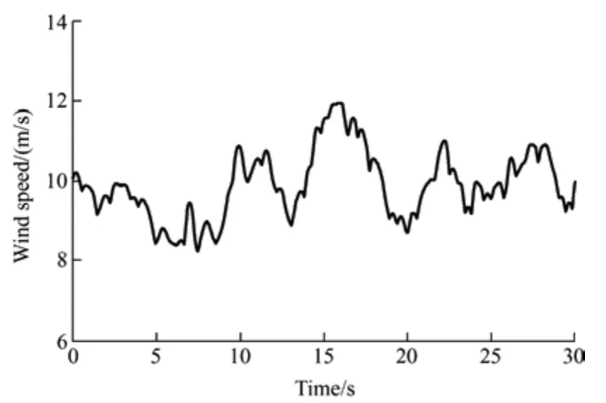
Fig.21 Actual wind speed profile
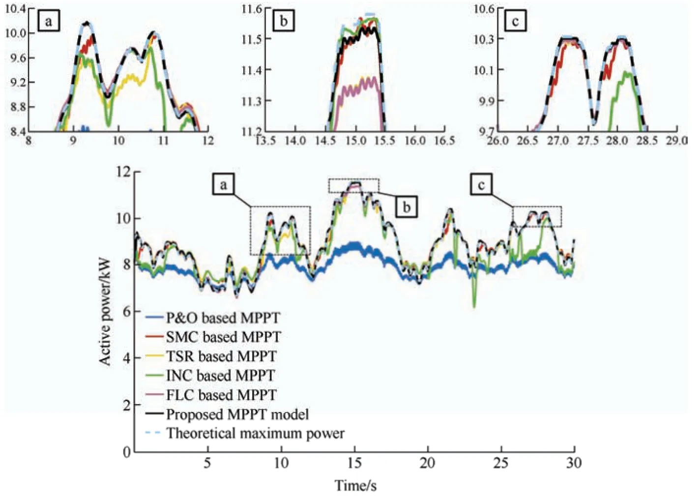
Fig.22 Output active power of the wind turbine generator

Fig.23 Difference between theoretical and actual maximum power corresponding to MPPT algorithms
wherePianddenote the actual and theoretical values of the WT active power,respectively,andndenotes the number of data points.Fig.24 presents a comparison of the MSE values computed using the MPPT algorithms.For better visualization,the MSE bar charts are plotted on a logarithmic scale.As shown in Fig.24,the proposed controller exhibits the lowest MSE value among the simulated MPPT schemes.Although the fuzzy logic control model also provides an acceptable result,the sensitivity of the proposed controller to changes in wind speed was higher owing to the use of an MPC block to generate switching signals.Therefore,the maximum power tracking error was minimized.
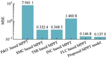
Fig.24 Mean squared error (MSE) computed for MPPT algorithms
The PMSG terminal voltages and currents are presented in Fig.25.Fig.26 shows the DC-link voltage obtained by applying the proposed FLC-MPC to a GS converter.The high accuracy of the proposed controller in regulating the DC-link voltage based on the reference value is evident from this figure.For further comparison,the controllers proposed in Ref.[15] and Ref.[17] are simulated under this scenario.The grid-aside active power obtained by adopting the proposed FLC-MPC controller and the controllers presented in Ref.[15] and Ref.[17] is shown in Fig.27.From the figure,a significant reduction in the active power fluctuations around the theoretical value is evident when the proposed controller was employed.
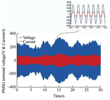
Fig.25 PMSG terminal voltage and current waveforms

Fig.27 Grid-side active power
5 Conclusions
This study proposed a new control model with maximum power point tracking capability by combining fuzzy logic control and model predictive control for a wind energy conversion system based on a permanent magnet synchronous generator.The proposed controller was applied to both machine-side and grid-side converters.The general structure of the proposed control model remained the same for both converters,whereas the control variables and FLC input and output parameters were different.The proposed controller was tested under two scenarios:simulated and actual wind speed profiles.The obtained results were compared with those of other control models and conventional MPPT algorithms presented in the literature.The simulation results confirmed that the proposed control model can track wind speed changes with high accuracy and minimal transient-state dynamics.In addition,the proposed control model results in a PMSG terminal current and voltage with the same phase angle,which proves the independent control of thed-qcurrent components.Furthermore,the performance of the grid-side converter under unity power factor conditions was guaranteed by adopting the proposed controller.By providing superior MPPT capability with minimum active power fluctuations,the lowest SRF and the highest system efficiency,the proposed controller can extract maximum power from the wind turbine compared to conventional MPPT controllers.
杂志排行

Chinese Journal of Electrical Engineering的其它文章
- Comparative Analysis of Vibration and Noise of Axial Flux Motor with Different Pole and Slot Combinations*
- Power Quality Improvement and Signal Conditioning of PV Array and Grid Interfaced Off-board Charger for Electric Vehicles with V2G and G2V Capabilities*
- Improved Control Strategy for Carbonized Cable Preparation in Low-voltage Arc Fault Test*
- Improved Approaches Toward Analysis of Electromagnetic Processes in Electrodynamical Devices Based on the Theory of Electromagnetic Field
- Filtered High Gain Observer for an Electric Vehicle’s Electro-hydraulic Brake: Design and Optimization Using Multivariable Newton-based Extremum Seeking
- Calculation of Available Transfer Capability Using Hybrid Chaotic Selfish Herd Optimizer and 24 Hours RES-thermal Scheduling