Optimal dispatch approach for rural multi-energy supply systems considering virtual energy storage
2023-12-28YanzeXuYunfeiMuHaijieQiHairunLiPengYuShuminSun
Yanze Xu ,Yunfei Mu ,Haijie Qi ,Hairun Li ,Peng Yu ,Shumin Sun
1.Key Laboratory of Smart Grid of Ministry of Education,Tianjin University,Tianjin 300072,P.R.China
2.Key Laboratory of Smart Energy &Information Technology of Tianjin Municipality,Tianjin University,Tianjin 300072,P.R.China
3.State Key Laboratory of Advanced Power Transmission Technology,State Grid Smart Grid Research Institute Co.,Ltd.,Beijing 102200,P.R.China
4.State Grid Shandong Electric Power Research Institute,Jinan 250002,P.R.China
Abstract: In response to the underutilization of energy and insufficient flexible operation capability of rural energy supply systems in China,this study proposes an optimal dispatch approach for a rural multi-energy supply system (RMESS)considering virtual energy storage (VES).First,to enable the flexible utilization of rural biomass resources and the thermal inertia of residential building envelopes,this study constructed VES-I and VES-II models that describe electrical-thermal and electrical-gas coupling from an electrical viewpoint.Subsequently,an RMESS model encompassing these two types of VES was formulated.This model delineates the intricate interplay of multi-energy components within the RMESS framework and facilitates the precise assessment of the adjustable potential for optimizing RMESS operations.Based on the above models,a day-ahead optimal dispatch model for an RMESS considering a VES is proposed to achieve optimal economic performance while ensuring efficient energy allocation.Comparative simulations validated the effectiveness of the VES modeling and the day-ahead optimal dispatch approach for the RMESS.
Keywords: Virtual energy storage;Rural multi-energy supply system;Multi-energy coupling;Optimal dispatch
0 Introduction
As global industrialization expands,inefficient energy use and ill-rationed infrastructure have exacerbated atmospheric contamination and intensified energy scarcity [1].In rural areas of northern China,approximately 41.5% of households rely on high-carbon and inefficient energy sources such as straw and coal for direct heating,resulting in significant carbon dioxide emissions and air pollution,which hinders the achievement of China’s goals for “carbon peak” and “carbon neutrality” [2].
In response to this challenge,China implemented a clean heating policy in its northern region in 2017.This strategic endeavor constitutes a pivotal initiative to realize energy substitution objectives and catalyze rural revitalization [3].Nevertheless,with the gradual implementation of distributed clean heating renovations based mainly on “coal-to-electricity conversion,” economic and practical challenges have become increasingly prominent [4].Rural regions have copious biomass energy resources,including agricultural residues,animal manure,and domestic sewage,unlike urban energy systems.Furthermore,these rural areas feature extensive untapped land and rooftop expanse,presenting substantial prospects for photovoltaic (PV)power generation [5,6].Hence,it is imperative to improve the effective conversion of biomass energy resources in rural settings and expedite the harmonious assimilation of renewable energy sources.This study aims to establish a novel rural energy-provisioning framework distinguished by elevated photovoltaic (PV)integration and multifaceted energy interconnections.
Biomass combined heat and power (CHP)technology has recently attracted considerable interest.This technology exhibits synergistic compatibility with intermittent PV resources,offering a dependable and environmentally sustainable energy provision for rural locales,effectively addressing their requirements for both electricity and heating [7,8].Reference [9] constructed a rural electricityheat integrated energy system (IES)with biomass,PV,and other renewable energy sources,and the results showed that the utilization of biomass CHP improved the efficiency of biomass utilization and enhanced the overall profitability of the IES.Reference [10] constructed a joint operation optimization model of biomass CHP considering multiple energy inputs,aiming to integrate the economics and energy efficiency of the electricity and heat supply systems.In [11],a strategy for energy dispatch within a multi-energy coupling system at the park level was developed.This strategy encompasses the integration of biomass CHP,reducing carbon emission intensity within the park.Simultaneously,it aims to optimize the park’s economic functionality and amplify the integration of renewable energy consumption.These prior investigations have paved the way for the practical application of biomass CHP systems.However,it is noteworthy that the heating systems investigated in these studies operate within a “power determined by heat “ paradigm,which necessitates continual equilibrium between heat output and load.This operational mode limits the energy utilization efficiency and flexibility of the energy-provisioning systems.
In rural multi-energy supply systems (RMESS),the diverse types,large quantities,varying physical forms,and regulation characteristics of multi-energy devices necessitate the inclusion of different operational constraints in optimal dispatch models.This inevitably results in numerous variables,constraints,and computational challenges [12].Virtual Energy Storage (VES)technology emerges as a promising approach that harnesses the inherent controllability potential of multi-energy systems [13],thereby transcending the conventional operational paradigm of biomass CHP that hinges on the “power determined by heat” principle [14,15].Based on the conversion effect of the CHP and other energy-coupling devices,the VES models the multi-energy adjustment potentials of the user side from an electrical viewpoint as equivalent parameters consistent with the external characteristics of battery energy storage.This modeling approach effectively reduces the number of variables and constraints in optimization problems,offering new insights into the economically flexible operation of RMESS [16].On the one hand,the gas storage mechanism integrated within biomass CHP installations exhibits a specific range of flexible adjustments,thereby facilitating the realization of VES functionality [17].In [18],a VES model was formulated through an indepth investigation of the adjustable potentials generated by the biomass gasification process.This model effectively accomplishes temporal load demand shifting,transferring energy consumption from periods of elevated costs to those characterized by reduced costs within the context of a multienergy system.Reference [19] considered a power-to-gas conversion device and achieved enhanced flexibility of a multi-energy microgrid by introducing a VES,resulting in reduced environmental pollution and operational costs.However,the thermal inertia inherent in residential building envelopes facilitates the modulation of residential heat loads while remaining within the bounds of thermal comfort,thus offering a prospect for its consideration as a VES,as demonstrated in a previous study [20].In [21],an innovative VES model was explicitly introduced for individual buildings.The efficacy of this model was substantiated through an assessment of its economic viability and environmental advantages in the context of optimal building energy system dispatch.Reference [22] developed a building-based VES model that utilized the heat storage capability of a building and further developed a dynamic economic dispatch model of the microgrid considering the VES.However,the above studies primarily focused on discussing a single type of VES without fully considering the synergistic effects of multiple types of VES in the optimal dispatch of multi-energy supply systems.The potential for the system operational flexibility may not have been fully explored,thereby affecting the economic performance of the system.
Residential buildings in the rural areas of China usually exist in the form of building clusters [23],and Centralized heating is mainly used in rural areas because of the differences in the distribution of rural biomass resources and the thermal efficiency of centralized biomass combustion surpasses that of decentralized direct combustion methods [24].Among the studies on aggregated VES for residential building clusters,Reference [25] developed an encompassing model for aggregating building VES and substantiating their capacity for energy conservation.reference [26] proposed an aggregated model and ruralgrid interaction architecture for a residential building VES in a rural scenario and performed a feasibility analysis.However,the above investigations did not incorporate the heat loss occurring in the hot water distribution network during the centralized heating setup when formulating the building’s VES aggregation model.Consequently,the potential exists for inadequate thermal comfort for users far from the heat source.
Building upon the preceding discourse,this study introduces an optimal dispatch approach tailored to an RMESS considering the VES.The primary contributions of this study are summarized as follows.
1)The flexible adjustment potentials of the gas storage device in the biomass CHP and the thermal load of the residential buildings were quantified as the VES-I and VESII models,respectively,and an RMESS model considering the two types of VES was constructed.It is essential to highlight that VES-II is an aggregated model of the building-level VES that considers the variations in heating power owing to different distances between residential buildings and the heat source.
2)Based on the flexible interaction between RMESS and the distribution network (DN),this study introduces a day-ahead optimal dispatch approach for RMESS while factoring in incorporating VES to enhance economic efficiency.This approach effectively facilitates the complete utilization of PV resources while concurrently mitigating the operational expenditure associated with the RMESS.
The remainder of this paper is organized as follows.Section 1 introduces the RMESS model considering the VES.Section 2 describes the day-ahead optimal dispatch model.Section 3 presents the case studies.Finally,Section 4 presents the conclusions of this study.
1 The RMESS model considering VES
1.1 Structure description
The structure of an RMESS,considering the VES,is shown in Fig.1.It integrates various components,including PV,DN,biomass CHP,multisource heat pumps (MHP),and residential building envelopes.The electrical load of the RMESS was provided by the PV,DN,and biomass CHP systems,whereas the heating load was supplied by the MHP.The biomass CHP consists of biomass energy gasification (BEG)equipment,a waste heat collector (WHC),a gas storage (GS)device,and a gas generator (GG).BEG converts biomass resources into natural gas through gasification and purification and is stored in the GS.The GG generates electricity by burning stored natural gas.The heat generated during electricity generation can be recovered and used through the WHC.The MHP has two heat inputs:the air source and waste heat generated by power generation from the biomass CHP.
GS has gas storage capability,and the electricalgas coupling property of BEG can be utilized to model BEG and GS as VES-I from an electrical viewpoint.The residential building envelopes have thermal inertia,and the electrical-thermal coupling characteristics of MHP can be used to model MHP and residential building envelopes as VES-Ⅱ from an electrical viewpoint.The difference between VES-I and VES-II is that VES-I relies on the electric-gas conversion equipment to describe the flexible adjustability of the GS storage capability from the electric side.In contrast,VES-II relies on the electric-heat conversion equipment to describe the flexible adjustability of the heat load of the residential buildings from the electric side,brought about by the heat storage characteristics of the building envelopes.Both VES-I and VES-II can be charged during periods of low electricity prices and discharged during periods of high electricity prices,thereby shifting the electrical load from peak to off-peak hours and providing the RMESS with a stable,flexible scheduling capability.In the RMESS,PV generation is the primary electricity source,supported by biomass CHP and rural DN.During periods of excess PV generation,excess electricity is used to charge the VES or sold to the DN.When the PV generation cannot meet the electricity demand,it is filled by the biomass CHP,VES output power,or power purchased from the DN.It is worth noting that this study is dedicated to optimizing the operational strategies of energy devices and exploring the VES capabilities of the RMESS to enhance overall energy supply efficiency and cost-effectiveness.Additionally,in the rural areas of China,energy supply systems are typically smaller in scale,and the distances between energy devices are relatively short [27].Therefore,this study disregards the energy supply losses resulting from the distributed connections of the energy devices in the RMESS.
1.2 RMESS mathematical model
1.2.1 PV model
The output power of the PV system mainly depends on the intensity of the solar irradiance.The maximum output power of the PV system at timetis shown in (1)[28]:
wherePPVsis the maximum output power of the PV under standard conditions,kW;Is(t)is the solar irradiance on the PV surface at timet,W/m2;Is,refis the reference value of the solar irradiance on the PV surface,W/m2;TPVsur(t)is the PV cell temperature at timet,℃;TPVsur,refis the reference value of the PV cell temperature,℃;anda,bandcare the compensation factors of the PV model.
The PV output should satisfy the following constraint:
1.2.2 Biomass CHP model
1)BEG model
Using gasification and purification methodologies,BEG employs a transformative approach to convert diverse biomass resources into natural gas [29].
The gasification process employs anaerobic fermentation technology to convert the organic constituents within biomass resources into biogas enzymatically.The outlined model is as follows:
whereVB(t)is the volume of biogas produced by the BEG at timet,m3;Vs(t)is the volume of biomass resource transported at timet,m3;ηBis the biogas production coefficient of the biomass resource;PBG(t)is the electric power of the BEG at timet,kW;ηstis the volume coefficient of biomass resource processing per unit of electricity consumption,m3/kW;ηspis the coefficient of the static sedimentation;andεomis the coefficient of the organic matter that can be used in the biomass resource.
ThePBGandVsshould satisfy the following constraint:
wherePBG,maxandPBG,minare the maximum and minimum values ofPBG,respectively (kW);are the upper and lower limits of the ramp rate of BG,respectively (kW/h);Vs,pre(t)is the predicted value of the volume of biomass resources transported at timet,m3;andNis the total number of dispatch periods.
The purification process encompasses desulfurization and decarburization treatments applied to biogas to enhance its methane content to align with the stipulated criteria for standard natural gas.The model is represented as follows:
whereVBP(t)is the volume of natural gas obtained after the purification treatment of biogas at timet,m3;andηB2Nis the purification coefficient.
2)GS model
The GS enables the storage and utilization of natural gas using the following storage balance model [30]:
whereSg(t)is the gas storage volume in the GS at timet,m3;Sg(t-1)is the gas storage volume in the GS at timet-1,m3;is the gas input of GS at timet,m3/h;andis the gas output of GS at timet,m3/h.
To ensure continuous utilization of the GS,the inputs and outputs within a dispatching period should remain balanced,as shown in (10).should also satisfy the constraints shown in (11)–(13):
whereSg,maxandSg,minare the maximum and minimum values ofSg,respectively,m3;andare the maximum and minimum values ofrespectively,m3/h;andandare the maximum and minimum values ofrespectively,m3/h.
3)GG model
The GG generates electricity by burning natural gas,and the relationship between electricity generation and natural gas consumption is as follows [29]:
WherePGG(t)is the generation power of GG at timet,kW;ηGGis the generation efficiency;lgis the calorific value of natural gas,kJ/m3;anddis the conversion value between calorific value and power,kJ/kW.
ThePGGshould satisfy the following constraint:
wherePGG,maxandPGG,minare the maximum and minimum values ofPGG,respectively (kW),andare the upper and lower limits of the ramp rate of the GG,respectively (kW/h).
4)WHC model
The heat collected by the WHC at timetis expressed as follows [29]:
whereQWHC(t)is the heat collected by WHC at timet,kW;andηcis the heat collection and recovery efficiency.
1.2.3 MHP model
The MHP is modeled as follows [31]:
whereQMHP(t)is the heating power of the MHP at timet(kW);PMHP(t)is the electric power of the MHP at timet(kW);andQair(t)is the energy absorbed from the air by the MHP at timet(kW).
MHP operation should satisfy the following electrical power constraints:
wherePMHP,maxandPMHP,minare the maximum and minimum values ofPMHP,respectively (kW),andare the upper and lower limits of the ramp rate of the MHP,respectively (kW/h).
1.2.4 VES model
1)VES-I
The modeling of VES-I uses the gas-buffering feature of the GS.During periods of low electricity prices or high PV output,VES-I was equivalently charged by increasing the power consumption of the BEG increasing the gas storage of the GS.Conversely,during periods of high electricity prices or insufficient PV output,VES-I is equivalently discharged by reducing the power consumption of the BEG,leading to a decrease in the gas storage of the GS.This process is described by defining the virtual charge-discharge power (PVES-I)and the virtual state of charge (SOCVES-I),as shown in Fig.2.
•PVES-I
Define the electric power of BEG that maintains a constant gas storage of GS as the baseline of electric power (Pbase-I).Combining (3),(4),and (9),the expression ofPbase-Iat timetis shown in (21):
Define the power deviation betweenPBG(t)andPbase-I(t)asPVES-I(t),as shown in (22).WhenPVES-I(t)>0,VES-I is charged.WhenPVES-I(t)<0,VES-I is in the discharge state.The value range ofPVES-I(t)depended on the constraints ofPBG.
•SOCVES-I
SOCVES-I(t)is defined as the ratio of the virtual power storage of VES-I (EVES-I)to the virtual capacity of VES-I (CVES-I)at timet,as expressed in (23):WhenSg(t)=Sg,min,SOCVES-I(t)=0;whenSg(t)=Sg,max,SOCVES-I(t)=1.
When the BEG is closed at timetandSgdecreases fromSg,maxtoSg,min,the corresponding power consumption is defined asCVES-I,as shown in (24).
where ΔτI(t)is the time thatSgdecreases fromSg,maxtoSg,minwhen BEG is closed at timet,h.
When the BEG is closed at timetandSgdecreases fromSg(t)toSg,min,the corresponding power consumption is defined asEVES-I,as shown in (25):
where ΔτEI(t)is the time thatSgdecreases fromSg(t)toSg,minwhen BEG is closed at timet,h.
2)VES-II
The modeling of VES-II uses the thermal inertia of the residential building envelopes.During low electricity prices or high PV output periods,the MHP output increases,storing excess heat energy in the residential building envelopes.This process is equivalent to the VESII charge process.Conversely,during high electricity prices or insufficient PV output,the MHP output is reduced,utilizing the pre-stored heat energy in the residential building envelopes.This process is equivalent to the VES-II discharge process.The construction of the VES model for a single building can be found in our previous study [32] and will not be repeated in this paper.
The number of rural residential buildings is large,and if single buildings are analyzed individually,it will result in a huge workload for building VES modeling and optimal dispatch calculation.Therefore,this paper extends the modeling of VES-II to an aggregated model for singlebuilding VES,addressing the quantification of VES in largescale rural residential buildings.Additionally,this approach provides sufficient VES capacity for interacting with the RMESS and DN.Therefore,the construction of the VES-II model in this paper considers the following two assumptions [33]:(1)The building envelope parameters are consistent among all residential buildings,and each residential building has the same heat demand;(2)The initial values of indoor temperatures in each residential building are the same;(3)Ignore the effect of occupancy and movement of the occupants in a single residential building on the VES modeling,and treat each residential building as a single-area building [34,35].
As shown in Fig.3,heat loss occurs in the heating pipeline network,and different distances from the residential building to the heat source result in different heat loss effects [36].We assume that the heat loss of the heating pipeline network varies linearly with the distance [37],and the modified VES-II parameters are calculated as follows:

Fig.3 Schematic diagram of heat loss in heating pipeline
wherePVES-Ⅱ,i(t)is the virtual charge-discharge power of theith building at timet,kW;nis the number of rural residential buildings;Pbase-Ⅱ,i(t)is the baseline of electric power of theith building at timet,kW [32];ηlossis the heat loss correction factor;liis the distance from theith building to the heat source,m;PVES-Ⅱ(t)is the aggregated virtual charge-discharge power at timet,kW;andSOCVES-Ⅱ(t)is the aggregated virtual state of charge at timet.
3)Coupling characteristics of the two VESs
As shown in Fig.1,VES-I and VES-II are not independent of each other in the RMESS but have a coupling relationship.
• Regarding the physical structure,VES-I and VES-II rely on GG and WHC to form linkages.In VES-I,the MHP operates in two modes:when=0,i.e.,Pbase-I(t)=0,the MHP operates in a mode with only air source input;when>0,i.e.,Pbase-I(t)>0,the WHC supplies the MHP as a second heat source in addition to the air source by capturing the waste heat generated by the GG power generation,which reduces the value ofPbase-Ⅱ(t)under the same conditions (for detailed reasons,refer to the Reference [32]),which reduces the operating electric power of the MHP,as expressed in Equation (26).However,the process of collecting waste heat by the WHC will cause energy loss;therefore,it is necessary to construct an optimal dispatch model,combine it with the renewable energy output,and reasonably select the working mode of the MHP.
• Regarding the energy interaction between the two VESs and the electric bus,both VES-I and VES-Ⅱ can directly interact with the electric bus,i.e.,a coupling relationship exists between the two on the electric bus side.To maintain the power balance of the electric bus and,at the same time,to ensure the operation economy of RMESS under the premise of meeting the user load demand,it is necessary to construct an optimal dispatch model to reasonably allocate the power of VES-I and VES-Ⅱ interacting with the electric bus.
2 Day-ahead optimal dispatch model
2.1 Objective function
In this study,we consider the economics of RMESS and propose an RMESS day-ahead optimal dispatch model considering VES.The objective functions are as follows:
whereCgridis the interaction cost between RMESS and DN,¥;Cmis the operation and maintenance cost of RMESS,¥;Cbwis the subsidized benefit of processing biomass resources,¥;CVESis the cost of VES invocation to reduce the impact of frequent VES invocations on the user comfort,¥;cbuyis the price at which RMESS purchases electricity from the DN,¥/kW;csellis the price at which RMESS sells electricity to the DN,¥/kW;Pgrid(t)is the power purchased from the DN by RMESS at timet,kW;Pexcess(t)is the power sold to the DN by RMESS at timet,kW;cMHP,cPV,cWHC,cGG,cGS,andcBGare the operation and maintenance cost coefficients of MHP,PV,WHC,GG,GS,and BG,respectively,¥/kW;εsis the subsidy coefficient of processing biomass resources,¥/m3;andcVES-IandcVES-Ⅱare the cost coefficients for invoking VES-I and VES-II,respectively,¥/kW.
2.2 Constraint conditions
1)Power balance constraints
In (31),PVES-I(t)andPVES-Ⅱ(t)are incorporated into the electric power balance constraints in the form of algebraic superposition,which can be used to make decisions on the numerical values of the two through the optimal dispatch model combinations,to achieve the economic optimization while satisfying the user load demand.
2)VES constraints
Combining (22),(23),(26),and (28),it can be seen that (32)constrains the electrical power of the MHP and the BG during the operation of the RMESS while ensuring that the room temperature and the gas storage volume of the GS are within limits.
wherePcmax-I(t)andPdmax-I(t)are the maximum charging and discharging power of VES-I at timet,respectively,subject to thePBGconstraints in (5)and (6),kW;andPcmax-Ⅱ(t)andPdmax-Ⅱ(t)are the maximum charging and discharging power of VES-II at timet,respectively,subject to thePMHPconstraints in (19)and (20),kW.
3)DN power interact constraints
wherePgrid,maxis the maximum purchased power of the RMESS (kW)andPexcess,maxis the maximum sold power of the RMESS (kW).
4)Equipment constraints
As shown in Eq.(2),(5-7),(10-13),(15-16),and (19-20).
2.3 Linearization of the objective function
TheCVESin the objective functionfcis a nonlinear absolute value function;therefore,it is necessary to linearize theCVES.The following new variables are introduced:
After linearization,the original problem becomes a linear programming problem that can be solved using mature solvers.In this study,we used the Gurobi 9.1.1 solver through the Yalmip toolbox in MATLAB R2020a to solve the day-ahead optimal dispatch model for RMESS considering VES.The interior point method was employed to obtain an optimal dispatch solution.
3 Case analysis
3.1 Input data and scenario setting
This study conducted a case simulation of an energy supply system in a rural area of northern China on a typical winter day.The simulation considered a total of 20 residential buildings,and the simulation period spanned 24 hours with a time step of 1 h (Δt).The device and operating parameters of the RMESS were selected from [38],whereas the residential building envelope parameters were obtained from [32].The indoor temperature range for the residential building is set as [19.71℃,25.02℃] according to [32].In Appendix A,Fig.A1 shows the outdoor temperature curve,and Fig.A2 shows the predicted curve of PV power.Table A1 lists the equipment parameters,Table A2 includes the residential building envelope parameters,Table A3 lists the operating parameters for the RMESS,and Table A4 provides the electricity prices,which can be referenced from [38].
Five scenarios are considered to validate the effectiveness of the proposed approach.
Scenario Ⅰ:Consider both VES-I and VES-Ⅱ.
Scenario Ⅱ:Consider only VES-I.
Scenario Ⅲ:Consider only VES-Ⅱ.
Scenario Ⅳ:VES is not considered.
Scenario Ⅴ:Only VES-II is considered,and the modeling process of VES-II ignores the distance difference from different residential buildings to the heat source.
3.2 Economic analysis
An economic comparison of scenarios I to IV is presented in Table 1.The power supply and consumption of the RMESS in the four scenarios are shown in Fig.4-7.Table 1 shows that the total cost in Scenario I is reduced by 9.8%,7.9%,and 17.7% compared to scenarios II-IV,respectively.The RMESS only has a PV output during the 9:00-18:00 period.During the 0:00-9:00 and 18:00-24:00 periods,the RMESS meets the electricity demand by purchasing power from the DN or relying on GG generation.In periods with low PV output,all the PV power was used to meet the electricity demand.During peak PV output periods,the RMESS sells excess electricity to the DN;thus,total PV consumption is realized in scenarios I–IV.At night,when the electricity price is low,the RMESS sells electricity to the DN at a negative price,and the purchased electricity is much cheaper than the generation cost.Therefore,the RMESS does not use the stored natural gas in the GS for power generation but relies heavily on purchasing electricity from the DN to meet the nighttime electricity demand.

Table 1 Economic comparison of scenarios I to IV
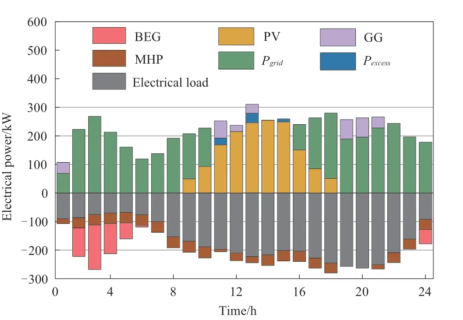
Fig.5 Power supply and consumption of RMESS for Scenario Ⅱ

Fig.6 Power supply and consumption of RMESS for Scenario Ⅲ
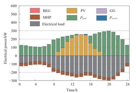
Fig.7 Power supply and consumption of RMESS for Scenario Ⅳ
Scenario Ⅳ does not consider VES,and the gas storage volume of GS and indoor temperature of residential buildings remain unchanged.Neither BEG nor GG worked in Scenario IV.First,considering operational economics,the RMESS tends to directly interact with the DN for electricity rather than relying on the GG for generation.Second,the gas storage volume of the GS remained the same in Scenario IV,and the excess electricity produced by the PV system could not be converted to natural gas for storage through the BEG.The RMESS,in this scenario,lacks the flexibility to respond to electricity prices.The total electricity consumption in each period of the scheduling day was generated based on the residential electricity load demand and heat load demand without adjusting according to electricity prices,resulting in the highest total cost.After considering the VES (scenarios I to III),the outputs of the BEG and MHP increase during periods of lower electricity prices and decrease during periods of higher electricity prices.This leads to a significant reduction in peak load during high-price periods and an increase in load during low-price periods,achieving the goal of “peak load shifting” while improving the economic efficiency of RMESS and reducing the system’s power supply pressure.Scenario Ⅱ only considers VES-I and the indoor temperature of residential buildings remains constant,so the MHP output only meets the residential building’s baseline heat load without flexibility.The electric power consumption of the BEG increased during the 23:00 and 00:00-7:00 periods to produce natural gas,thereby enhancing the gas storage volume of the GS.This stored gas can be utilized during high-price periods to compensate for any shortfall in the output of the PV system or sell excess electricity to the DN,thereby improving the economic performance of the RMESS.Scenario Ⅲ only considers VES-Ⅱ and the gas storage volume of GS remains unchanged.VES-Ⅱ reduces the operating cost by shifting the residential building’s heat load demand to periods of low electricity prices.Scenario I considers both VES-I and VES-Ⅱ,which can use the synergistic effect of the two to enable a larger portion of the load to be shifted to periods of low electricity prices.This further reduces the operational costs of the RMESS.In Fig.4,the time periods 23:00 and 1:00-7:00 represent low electricity price periods,during which the BEG produces and stores natural gas in the GS.During the remaining time periods,the GG consumes the stored natural gas to generate electricity,maintaining a balanced input and output of the GS throughout the dispatching day to ensure continuous utilization.Specifically,at 11:00,the GG generated electricity to compensate for the insufficient output from the PV system.During the 13:00-15:00 period,which corresponds to the highest electricity selling price of the day,the GG chooses to generate electricity and sell it to the DN to improve the economic performance of the RMESS.From 19:00 to 21:00,which is the period with the highest electricity purchase price throughout the day,the GG chooses to generate electricity to reduce the purchased electricity consumption of the RMESS while ensuring a balanced input and output of the GS.In Scenario V,the total operating cost of the RMESS was ¥1907.6,which is 3.8% lower than that in Scenario III.Scenario V ignores the heat loss due to the distance between the residential buildings and the heat source.As shown in Fig.8,the electric power of the MHP in Scenario V is lower than that in Scenario III in each dispatching period,which leads to less purchased power in Scenario V.
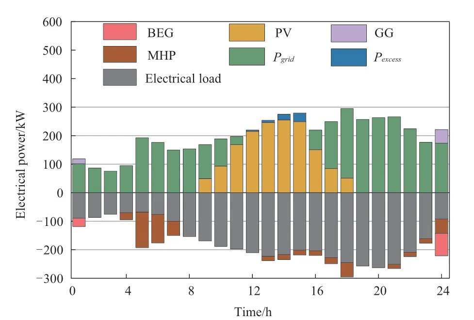
Fig.8 Power supply and consumption of RMESS for Scenario V
3.3 Analysis of VES dispatch results
Figs.9 and 10 show the virtual charge-discharge power and virtual state of charge of VES-I and VES-II for scenarios I to III.The VES tends to charge during periods of lower electricity prices and discharge during periods of higher prices.In Scenario I,VES-I and VES-Ⅱ make decisions before 7:00,resulting in significant peaks in virtual charge-discharge power.VES-I and VES-Ⅱ perform pre-charging,andSOCVES-IandSOCVES-Ⅱquickly reach their maximum values.During the high-price period from 7:00 to 23:00,VES-I and VES-II discharge,reducing the purchased electric power of the RMESS and thus saving operating costs.In the 23:00-24:00 period,VES-I and VESII charge simultaneously to ensure a balanced state of the gas storage volume of the GS and the indoor temperature of residential buildings within one dispatch cycle,providing sufficient dispatchable space for the next day.During the low-electricity price period from 23:00 to 7:00,the combined charging power of VES-I and VES-II in Scenario I was greater than that achieved when considering VES-I or VES-II individually.Therefore,Scenario I leveraged the synergistic effects of VES-I and VES-II,reducing operating costs for the RMESS.

Fig.9 PVES-Ⅰ and PVES-Ⅱ for scenarios I to III
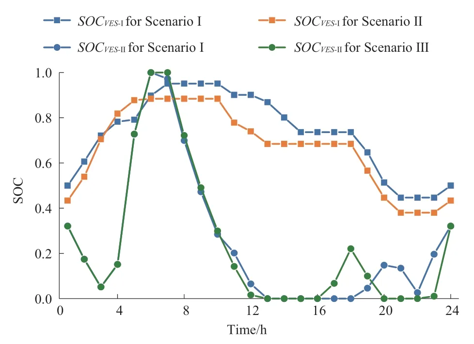
Fig.10 SOCVES-Ⅰ and SOCVES-Ⅱ for scenarios I to III
Scenarios II and III considered only a single type of VES.However,scenario Ⅱ has a 7.3% lower purchasing cost than scenario Ⅲ,indicating that VES-I can provide greater flexibility for optimizing the operation of RMESS.
The VES-II modeling method used in this study was compared with the modeling method of Scenario V to verify the effect of the method on the thermal comfort of residential buildings.The residential building farthest from the heat source was the most affected by heat loss in the heating pipeline network.Therefore,this study selected the residential building farthest from the heat source to analyze its thermal comfort in scenarios III and V.Fig.11 shows the comparison of theSOCVES-Ⅱin the farthest residential building from the heat source in scenarios Ⅲ and V.
The comparison shows that in Scenario V,theSOCVES-Ⅱis consistently below the lower limit after 9:00,and the peak output of the MHP at 7:00 does not fully charge VES-Ⅱ.This is because scenario V did not consider the heat loss in the heating pipeline network,resulting in the actual output of the MHP in the residential building farthest from the heat source is lower than the optimized value.
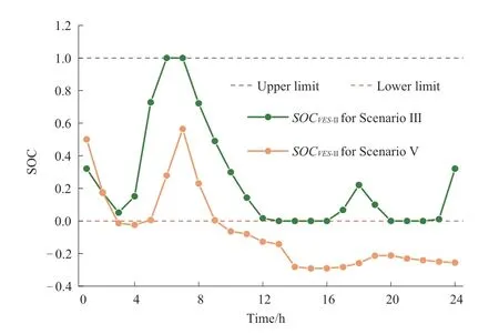
Fig.11 Comparison of the SOCVES-Ⅱ in the farthest residential building from the heat source in scenarios Ⅲ and V
4 Conclusion
In this study,we propose a day-ahead optimal dispatch approach for RMESS that considers VES,aiming to explore the operating flexibility of RMESS by constructing VES models.The conclusions of this study are as follows.
1)In this study,the gas storage capabilities of the GS and the residential building envelope thermal inertia were modeled as VES-I and VES-II,respectively.Considering the two types of VES,the total cost of the RMESS is reduced by 17.7%,demonstrating the flexible operating potential of the RMESS.When considering only one type of VES,VES-I can reduce the power purchase cost of RMESS by 6.2% compared with VES-Ⅱ,indicating that VES-I can provide more dispatchable space for optimizing the operation of RMESS.
2)The modeling of VES-Ⅱ in this paper considers the deference in heating power due to the distance between residential buildings and the heat source.TheSOCVES-Ⅱis strictly between 0 and 1 by introducing a heat loss correction factor.This modeling approach ensures thermal comfort for all users and avoids the issue of overcooling for users located far from the heat source in winter heating scenarios.
In this study,the source-load complex uncertainties in the RMESS were not sufficiently considered,and future work will focus on the multi-energy VES modeling method under the influence of uncertainties and the multi-timescale adaptive optimal dispatch approach of the RMESS.This study ignores the energy supply losses caused by the distributed connection of energy devices in the RMESS.Future work will fully consider the impact of energy supply losses on the actual operation of the RMESS.
Nomenclature
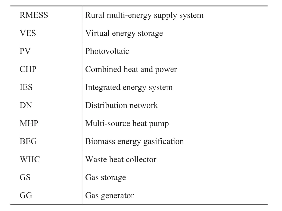
A.Abbreviations

B.Parameters

continue

C.Variables
Acknowledgements
This work is supported by Science and Technology Project of SGCC (5108-202218280A-2-375-XG).
Declaration of Competing Interest
We declare that we have no conflict of interest.
Appendix A

Fig.A1 Outdoor temperature curve

Fig.A2 Predicted curve of PV power

Table A2 Detailed material parameters for residential building envelopes
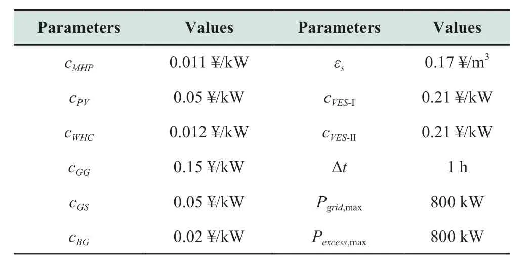
Table A3 Operating parameters of RMESS

Table A4 Electricity price
杂志排行

Global Energy Interconnection的其它文章
- Over-limit risk assessment method of integrated energy system considering source-load correlation
- Federated double DQN based multi-energy microgrid energy management strategy considering carbon emissions
- Coordinated planning for flexible interconnection and energy storage system in low-voltage distribution networks to improve the accommodation capacity of photovoltaic
- Layered power scheduling optimization of PV hydrogen production system considering performance attenuation of PEMEL
- Application of four machine-learning methods to predict short-horizon wind energy
- A robust optimization model for demand response management with source-grid-load collaboration to consume wind-power