Investigation of magnetization reversal and domain structures in perpendicular synthetic antiferromagnets by first-order reversal curves and magneto-optical Kerr effect
2023-12-02XiangQianWang王向谦JiaNanLi李佳楠KaiZhouHe何开宙MingLingXie谢明玲andXuPengZhu朱旭鹏
Xiang-Qian Wang(王向谦), Jia-Nan Li(李佳楠), Kai-Zhou He(何开宙),Ming-Ling Xie(谢明玲), and Xu-Peng Zhu(朱旭鹏)
1School of Physics Science and Technology,Lingnan Normal University,Zhanjiang 524048,China
2Key Laboratory of Sensor and Sensor Technology,Institute of Sensor Technology,Gansu Academy of Sciences,Lanzhou 730000,China
Keywords: perpendicular synthetic antiferromagnet, first-order reversal curves, magnetization reversal process,domain
1.Introduction
Magnetic tunnel junctions (MTJs) based on perpendicular magnetic anisotropy (PMA) have already been widely used in spin-transfer-torque magnetic random access memory(STT-MRAM)and magnetic sensors because of its higher magnetic storage density and good thermal stability.[1–3]The PMA and exchange bias field of the perpendicular syntheticantiferromagnet(p-SAF)layer as the pinned layer in MTJ can be regulated more efficiently than traditional antiferromagnetic materials.[4,5]The interlayer exchange coupling (IEC)of the p-SAF layer will be converted into a Ruderman–Kittel–Kasuya–Yosida (RKKY) type as a function of NM thickness.[6,7]The p-SAF layer is comprised of two ferromagnetic(FM)layers that are spaced apart by a nonmagnetic(NM)metal spacer.Therefore, FM/NM/FM system could be toggled between the FM or AFM coupling by changing the thickness of the spacer.Some PMA multilayer stacks can act as FM layers in p-SAF systems, such as Co/Pt,[8]Co/Pd,[9]and Co/Ni.[10]Among them, the significant PMA, which originates from 3d–5d spin–orbit coupling and damping coefficient of Co/Pt or Co/Pd multilayers,creates a high switching current density (Jc) in the spintronic device.[10]However, the PMA of Co/Ni multilayer mainly originates from two reasons:[11](i) only one valence electron difference at the interfaces of an ultrathin dense stack of Co and Ni, and (ii) the spin–orbit coupling between dxyand dx2-y2of Co/Ni interfaces.Furthermore, the main advantage of (Co/Ni) multilayers is that they are non-heavy metals, leading to a low damping coefficient.The magnetization precession at the interface of ferromagnetic(FM)/non-magnetic(NM)metal multilayer will transfer spins to the adjacent NM layers, which can also dissipate spin energy and therefore enhance the effective damping constant via spin-pumping effect.But this phenomenon can be avoided in(Co/Ni)multilayers.
Therefore,the(Co/Ni)multilayers possess the higher superiority in the application of the spintronic device.Subhiet al.found the PMA of(Co/Ni)Nmultilayer is the most significant when Co/Ni bilayer repetitionsN=4–8,and the(Co/Ni)fcc(111)texture is improved and the magnetic domain size decreases exponentially with the increase ofN.[12]According to Chenet al., changing the thickness of the Ru spacer and the composition of the ferromagnetic(FM)layer at the FM/Ru interfaces can adjust the IEC of synthetic-antiferromagnet(SAF)structure based on Co/Ni perpendicular multilayer.[13]In Irbased SAF,Nisrit Pandeyet al.discovered that the multilayer design of the individual ferromagnetic layers can affect the chirality of domain walls and the interfacial Dzyaloshinskii–Moriya interaction.[14]However, there are few reports about systematic research on the irreversible magnetic reversal and switching field distribution caused by changing the NM thickness in SAF structure.First-order reversal curve (FORC) is a powerful tool for analyzing the magnetization reversal process of magnetic multilayer.FORC provides more information about the details of magnetization reversal,the distribution of the irreversible switching field,and the position of domain nucleation and annihilation than major hysteresis loops.[15]An FORC is a magnetization curve measured between the lower extreme value and the upper extreme value of an external driving fieldH.In the process of FORC measurement,the sample is saturation-magnetized in the forward saturation fieldHsat.The external area is reduced to a specific flipping fieldHr,and the applied magnetic fieldHgradually increases to the saturation fieldHsat.The entire magnetization process is recorded,and the magnetization corresponding to any magnetic fieldH(H≦Hr) can be expressed asM(Hr,H) on an FORC curve that is produced.A series of FORC curvesM(Hr,H) can be obtained by measuring the FORC curves for different values ofHand repeating the above measurement process to sample the entire area enclosed by the main hysteresis loop.The FORC distribution is generally evaluated as the second derivative of the magnetization(M)with respect toHandHras follows:[16]
and then plotted as a counterplot in a rotated coordinate system;Hc=(H-Hr)/2 andHu=(H+Hr)/2 as coercive field axis and interaction field axis,respectively.
In our previous work,we have characterized the magnetization reversal processes of[Pt/Co(x)]Nmultilayers with only FM coupling by FORC (DOI:10.1088/1361-6463/ab78d7).Therefore,for comparison,a series of p-SAFs based on Co/Ni stacks with varying thickness of Ir spacer layer are fabricated in this work.According to test results of Kerr loops, domain topology,and FORCs,we find that the magnetization reversal process and SFD in AFM are different from those in the FM coupling multilayer films.
2.Materials and methods
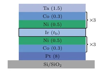
A series of p-SAF films consisting of Pt(8)buffer layer,bottom and upper [Ni (0.5)/Co (0.3)]3multilayers separated by Ir spacer, and Ta (1.5) capping layer were deposited on Si/SiO2substrates using a magnetron sputtering system(DC,Ar flow rate: 20 sccm).The numbers in parenthesis are the thicknesses of each layer in nm.Ir spacer’s thickness(tIr)varied from 0.35 nm to 4.9 nm.Figure 1 shows the corresponding structure schematics.The sample’s magnetization reversal processes were identified by vibrating sample magnetometers’hysteresis loops and FORC(VSM,Lakeshore 8600).The FORC was measured by first saturating the sample at a large positive field, then decreasing the field to a reversal fieldHr,and measuring the magnetizationMas the applied fieldHis increased back to saturation.A subsequent FORC is measured after re-saturating the sample and then ramping the field to a lower reversal field,Hr.As the reversal fields are changed,the interior of the main loop is filled with the FORCs.The domain structure was characterized by magneto-optical Kerr effect(MOKE)microscopy.

3.Results
As a demonstration, the out-of-plane Kerr loops of[Pt/(Co/Ni)3]/Ir(tIr)/[(Ni/Co)3/Ta] p-SAF films, whentIrvaried from 0.35 nm to 4.9 nm, are displayed in Fig.2(a).It can be seen that all the samples have obvious PMA.When thetIr=0.35 nm,the hysteresis loops are approximately rectangular.However, a step-shape Kerr loop appears when thetIrincreases to 0.75 nm,which means that the AFM coupling between the FM layers below and above the Ir spacer layer and the saturation field substantially increase from 19 mT to 75 mT approximately.With thetIrprogressively increasing,two types of hysteresis loops appear alternately, whereas theHexchanges from 0 mT to the middle value of the first reversal in Kerr loops.
The oscillatory variation of theHexis presented as a function oftIrin Fig.2(b).The strongest peak ofHexis observed attIr=0.75 nm,and with the increase oftIr,theHexbecomes weak according to RKKY-type coupling at 1.05 nm, 2.1 nm,4.55 nm,and 4.9 nm in sequence.The samples with AFM coupling are denoted as S1–S5 according to the increasing order oftIr.

The magnetic domain structure of S1 is displayed in Fig.3 to show the magnetization reversal process more intuitively.We mark a–f points for positive saturation,each inflection point, and negative saturation in the Kerr loops, respectively,and the corresponding domain images are shown on the right-hand side.When the magnetic field is 95 mT (point a),the sample is of positive saturation,and all the moments spin up.When theHdecreases to 61.6 mT(point b),a slice domain is reversed.The step at point b corresponds to the reversal of the bottom(Co/Ni)3stack,as resolved by depth-sensitive Kerr measurements,and it is wholly flipped at c point.With theHinversely increasing to the d point, some bubble domains are observed because of the nucleation of the upper layer(Ni/Co)3stack.Noteworthily, the luminosity at e point is lighter than that at c point.This is because the Kerr signal is intensified,which can be observed from the illustration.In our opinion,that results from the high exchange coupling effect of AFM structure.The spin state of Co/Ni stacks is displayed in each corresponding stage,respectively.It can be found that the domain switching process of the upper Co/Ni stack and the bottom Co/Ni stack are different due to the AFM coupling.
The domain nucleations in the upper Co/Ni stack and bottom Co/Ni stack of S1–S5 are investigated as shown in Fig.4.In the case of the upper stack,the domain size of S1 is only approximately 6µm,however,it rapidly increases to 600µm in S2.The domain size of S3 has a slight increase compared with that of S2, however, it dramatically decreases to 5 µm whentIr=1.05 nm.In the last sample,the domain size rises again to approximately 60µm.For the bottom Co/Ni stack,the transformation law is similar to the counterpart of the upper Co/Ni stack: the domain size of S1 is slightly larger than that of S2 but much lower than that of S3.After increasingtIr, the domain size shrinks to about 6µm monotonously.


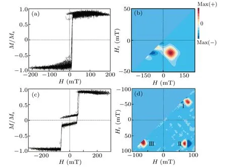
Additionally, we use FORCs, a more precise and thorough method of characterizing the magnetization reversal of magnetic multilayer film,to provide the degree of irreversible switching and magnetostatic interaction distributions for investigating the behavior of the samples’magnetization reversal.A typical FORC is comprised of multi-minor loops whose values of the reversal field,Hr, are different.As shown in Fig.5,a family of FORCs whentIr=0.35 nm in Fig.5(a)and 0.7 nm in Fig.5(c)are displayed.All the curves are fishboneshaped.Suppose that the magnetization on one FORC is defined asM(Hr,H), whereHis the applied magnetic field andHris the starting reversal field, then the FORC distribution will be determined by a mixed second-order derivative.This second-order derivation eliminates the reversible magnetization process.Therefore, a plot of the FORC distributionρ(Hr,H)can be created to probe the details of the irreversible magnetization reversal process.[16]The FORC distribution of FM sample is different from that of AFM sample.In the FM coupling sample(tIr=0.35 nm),only a peak is observed from-50 mT to-40.7 mT along theHraxis.

However,in addition to two peaks,a pair of peak–valley is located in range from-60 mT to-88.6 mT in the AFM coupling sample (tIr=0.7 nm).Combined with the results of MOKE,the FORC distributions in AFM coupling samples could be divided into three areas:[15,17]region I,region II,and region III.Region I signifies the irreversible domain nucleation process of the bottom layer.In this case,upper Co/Ni stack and bottom Co/Ni stack manifest FM coupling and the moments are all aligned in the same direction.Therefore, the system only has an average value of positive interaction field distribution.Compared with the distribution of region I,the distribution of region II reveals a peak–valley pair.This phenomenon can be attributed to the antiparallel alignment of magnetic moments between the upper Co/Ni stack and bottom Co/Ni stack which arises from the effect of AFM coupling.The region III satisfies the irreversible domain nucleation process of the upper Co/Ni stack,the interaction between the upper Co/Ni stack and the bottom Co/Ni stack is FM coupling and reveals a positive peak in FORC distribution.Consequently, the coupling between the upper (Co/Ni)3stack and the bottom (Co/Ni)3stack transforms from FM into AFM, generating a negative interaction distribution in the p-SAF film.Therefore,the peakvalley pair will appear in the FORC distribution of AFM coupling sample.
The FORC distributions of other AFM samples from S2 to S5,which possess the peak-valley pairs,are shown in Fig.6 to study the pattern of change more clearly.It can be found that the position and range of the irreversible magnetization reversal process change withtIrincreasing.Compared with S1, the region I is shifted to-10.3 mT In summary, we investigated the domain structure and magnetization reversal process of a p-SFA film consisting of the (Co/Ni)3/Ir(tIr)/(Ni/Co)3withtIrvarying from 0.35 nm to 4.9 nm.Kerr loops’results show an RKKY-type coupling law,and the strongest peak ofHexis observed attIr=0.7 nm.The domain switching process of the upper Co/Ni stack is different from that of the bottom Co/Ni stack due to the AFM coupling.Comparing with FM coupling film, the FORC distribution of AFM coupling sample has two peaks and a pair of peak–valley caused by a negative interaction distribution in p-SAF film.WhentIr=0.7 nm,for the bottom(Co/Ni)3stack,the irreversible domain nucleation field is located in a range of 45.6 mT Acknowledgements Project supported by the Natural Science Foundation of Gansu Province, China (Grant No.22JR5RA775), the Science and Technology Program of Lanzhou, China (Grant No.2021-1-157), the Guangdong Basic and Applied Basic Research Foundation, China (Grant Nos.2020A1515110998 and 2022A1515012123), the Outstanding Youth Foundation of Gansu Academy of Science, China (Grant No.2021YQ-01), and the Innovative Team Construction Project of Gansu Academy of Sciences,China(Grant No.2020CX005-01).
4.Conclusions
杂志排行
Chinese Physics B的其它文章
- Optimal zero-crossing group selection method of the absolute gravimeter based on improved auto-regressive moving average model
- Deterministic remote preparation of multi-qubit equatorial states through dissipative channels
- Direct measurement of nonlocal quantum states without approximation
- Fast and perfect state transfer in superconducting circuit with tunable coupler
- A discrete Boltzmann model with symmetric velocity discretization for compressible flow
- Dynamic modelling and chaos control for a thin plate oscillator using Bubnov–Galerkin integral method
